EP0756669B1 - Dichtungsanordnung für einspritzventile an kraftstoffzuleitungen - Google Patents
Dichtungsanordnung für einspritzventile an kraftstoffzuleitungen Download PDFInfo
- Publication number
- EP0756669B1 EP0756669B1 EP95914336A EP95914336A EP0756669B1 EP 0756669 B1 EP0756669 B1 EP 0756669B1 EP 95914336 A EP95914336 A EP 95914336A EP 95914336 A EP95914336 A EP 95914336A EP 0756669 B1 EP0756669 B1 EP 0756669B1
- Authority
- EP
- European Patent Office
- Prior art keywords
- sealing
- branch
- sealing element
- rail
- ring
- Prior art date
- Legal status (The legal status is an assumption and is not a legal conclusion. Google has not performed a legal analysis and makes no representation as to the accuracy of the status listed.)
- Expired - Lifetime
Links
- 238000007789 sealing Methods 0.000 title claims abstract description 76
- 239000000446 fuel Substances 0.000 title claims abstract description 22
- 238000002347 injection Methods 0.000 title claims abstract description 18
- 239000007924 injection Substances 0.000 title claims abstract description 18
- 239000000463 material Substances 0.000 claims abstract description 7
- 238000002485 combustion reaction Methods 0.000 claims abstract 2
- 238000009434 installation Methods 0.000 claims description 15
- 239000011324 bead Substances 0.000 claims description 3
- 230000000694 effects Effects 0.000 claims description 3
- 229920001971 elastomer Polymers 0.000 claims description 3
- 239000000806 elastomer Substances 0.000 claims description 2
- 230000008961 swelling Effects 0.000 abstract description 6
- 238000001816 cooling Methods 0.000 abstract 1
- 238000005553 drilling Methods 0.000 abstract 1
- 239000011796 hollow space material Substances 0.000 abstract 1
- 230000013011 mating Effects 0.000 abstract 1
- 239000002184 metal Substances 0.000 abstract 1
- 230000002093 peripheral effect Effects 0.000 description 2
- 238000005057 refrigeration Methods 0.000 description 1
- 239000007787 solid Substances 0.000 description 1
- 239000000243 solution Substances 0.000 description 1
Images


Classifications
-
- F—MECHANICAL ENGINEERING; LIGHTING; HEATING; WEAPONS; BLASTING
- F16—ENGINEERING ELEMENTS AND UNITS; GENERAL MEASURES FOR PRODUCING AND MAINTAINING EFFECTIVE FUNCTIONING OF MACHINES OR INSTALLATIONS; THERMAL INSULATION IN GENERAL
- F16L—PIPES; JOINTS OR FITTINGS FOR PIPES; SUPPORTS FOR PIPES, CABLES OR PROTECTIVE TUBING; MEANS FOR THERMAL INSULATION IN GENERAL
- F16L41/00—Branching pipes; Joining pipes to walls
- F16L41/08—Joining pipes to walls or pipes, the joined pipe axis being perpendicular to the plane of a wall or to the axis of another pipe
- F16L41/088—Joining pipes to walls or pipes, the joined pipe axis being perpendicular to the plane of a wall or to the axis of another pipe fixed using an elastic grommet between the extremity of the tube and the wall
-
- F—MECHANICAL ENGINEERING; LIGHTING; HEATING; WEAPONS; BLASTING
- F02—COMBUSTION ENGINES; HOT-GAS OR COMBUSTION-PRODUCT ENGINE PLANTS
- F02M—SUPPLYING COMBUSTION ENGINES IN GENERAL WITH COMBUSTIBLE MIXTURES OR CONSTITUENTS THEREOF
- F02M61/00—Fuel-injectors not provided for in groups F02M39/00 - F02M57/00 or F02M67/00
- F02M61/14—Arrangements of injectors with respect to engines; Mounting of injectors
- F02M61/145—Arrangements of injectors with respect to engines; Mounting of injectors the injection nozzle opening into the air intake conduit
-
- F—MECHANICAL ENGINEERING; LIGHTING; HEATING; WEAPONS; BLASTING
- F02—COMBUSTION ENGINES; HOT-GAS OR COMBUSTION-PRODUCT ENGINE PLANTS
- F02M—SUPPLYING COMBUSTION ENGINES IN GENERAL WITH COMBUSTIBLE MIXTURES OR CONSTITUENTS THEREOF
- F02M69/00—Low-pressure fuel-injection apparatus ; Apparatus with both continuous and intermittent injection; Apparatus injecting different types of fuel
- F02M69/46—Details, component parts or accessories not provided for in, or of interest apart from, the apparatus covered by groups F02M69/02 - F02M69/44
- F02M69/462—Arrangement of fuel conduits, e.g. with valves for maintaining pressure in the pipes after the engine being shut-down
- F02M69/465—Arrangement of fuel conduits, e.g. with valves for maintaining pressure in the pipes after the engine being shut-down of fuel rails
-
- F—MECHANICAL ENGINEERING; LIGHTING; HEATING; WEAPONS; BLASTING
- F02—COMBUSTION ENGINES; HOT-GAS OR COMBUSTION-PRODUCT ENGINE PLANTS
- F02D—CONTROLLING COMBUSTION ENGINES
- F02D2200/00—Input parameters for engine control
- F02D2200/02—Input parameters for engine control the parameters being related to the engine
- F02D2200/06—Fuel or fuel supply system parameters
- F02D2200/0606—Fuel temperature
-
- F—MECHANICAL ENGINEERING; LIGHTING; HEATING; WEAPONS; BLASTING
- F02—COMBUSTION ENGINES; HOT-GAS OR COMBUSTION-PRODUCT ENGINE PLANTS
- F02M—SUPPLYING COMBUSTION ENGINES IN GENERAL WITH COMBUSTIBLE MIXTURES OR CONSTITUENTS THEREOF
- F02M2200/00—Details of fuel-injection apparatus, not otherwise provided for
- F02M2200/85—Mounting of fuel injection apparatus
- F02M2200/858—Mounting of fuel injection apparatus sealing arrangements between injector and engine
Definitions
- the invention relates to a sealing arrangement according to the preamble of claim 1.
- a sealing arrangement according to the preamble of claim 1.
- this sits in a radially outer groove of the valve housing, the end to be connected to the fuel supply line is formed by a groove-limiting flange which abuts an annular surface which is at the bottom of the circular cylindrical line branch for receiving the valve housing is located and the line is drilled at the branch point; see Fig. 8.
- a disadvantage of such a sealing arrangement is that the sealing elements used for the refrigeration must have special material properties in order to be suitable, and yet fail at low temperatures of below minus 40 ° Celsius if the swelling of the O-ring by the fuel is no longer sufficient to prevent the sealing member from causing radial leakage; see. G. Streit and M. Achenbach: "Functionality of elastomer seals at low temperatures using the example of O-rings, part 2: Influence of fuels on the sealing force at low temperatures" in "Kautschuk, Gummi, Kunststoffe KGK, International Trade Journal for Polymeric Materials” , 10/93 (October 1993, 46th year), page 812 ff.
- the invention has for its object to provide a sealing arrangement of the type mentioned, which is also below minus 40 ° Celsius and insufficient or absent (for example Breaks) swelling of the sealing element (O-ring) ensures a secure seal of the connector of the injection valve and the associated branch of the fuel supply line.
- This object is achieved essentially by the characterizing features of claim 1.
- the advantage of this solution to the problem is that ordinary sealing rings can be used as sealing elements without special properties at low temperatures and the tightness is still guaranteed if, as a result or due to a temporary lack of fuel supply, swelling is no longer able to compensate for the cold-related shrinkage of the sealing element.
- the invention is based on the knowledge that a sealing element which is not fastened to the wall of the installation space shrinks radially inward onto its carrier and thereby increases the radially inner sealing effect, while the radially outer sealing effect is reduced.
- the sealing arrangement according to the invention can be configured by the characterizing features of the subclaims, but this does not exhaust the configuration options.
- the proposed positive connection of the sealing element according to the invention with the associated branch of the fuel supply line causes the sealing element to be held at the supply branch before the injection valve is inserted and secured.
- the clamp-like sealing element ensures the cohesion of the injection valve and the line branch, the flange adapter being involved, which could be formed in one piece with the fuel supply line.
- WO 91/11610 discloses both a generic sealing arrangement according to the preamble of claim 1 at the end (14) of the injection valve (10) adjacent to the fuel feed line (18) - an arrangement which does not entirely correspond to the known sealing arrangements described at the outset because there is no flange of the valve housing strikes the branch (16) of the feed line (18), but the piston-like valve end (14) engages "telescopically" in the branch (16) - as well as a generic seal arrangement at the end (12) adjacent to a distributor (22) ) of the valve (10), where in connection to an outer collar (32) of the valve housing, which replaces the known flange for axially limiting the annular groove (26) for receiving the sealing element (34), a continuation of the groove base as the outer end of the valve housing without contact in a bore (20) of the distributor 822), while the substantially L-shaped sealing element (34), d he is axially longer than radially thick and is supported with its thicker section in the annular groove (26), although it touches the annular circumference
- the axially front annular end face of the sealing element (34) lies against a shoulder (38) which is formed by the distributor bore (20) and a further blind bore (36) in the distributor (22) while the radia! outer peripheral surface (42) of the sealing element (34) touches the wall of the blind bore (36) as long as there are no low temperatures. If this is the case, however, this contact ends and the sealing element (34) shrinks radially inside onto the valve end (12), whereby it cannot overlap the collar (32) and cannot seal against the outermost end of the housing.
- a radial but instead an axial seal takes place at the housing end (12) near the distributor, rather than at the inlet end (14), which can still seal when the sealing element (34) shrinks radially, but due to the omission of the sealing section the outer surface area (42) of the sealing element is exposed to an increased pressure gradient when the feed line (18) is under pressure at all.
- Identical or corresponding structures (parts, surfaces, Spaces) of different embodiments have reference numbers referred to, which differ by a multiple of 100 and by their hundreds digits the number of the Embody embodiment.
- the reference numbers below 100 apply for Fig. 8 (prior art).
- a circular-cylindrical branch 112 is formed vertically on a circular-cylindrical fuel supply line 110, namely a distributor line for a plurality of injection valves, which has a central bore 114 connected to the cavity of the supply line 110 and a solid base molded onto the wall of the supply line 110 116, which lines the bore 114 with a radially inwardly stepped ring-shaped base 118, the radially outer part 118.1 of which delimits an installation space 120 axially against the feed line 110, and the radially inner part 118.2 of which faces the radial end face of the valve housing 122 of an injection valve.
- the end of the valve housing 122 close to the feed line shown in FIG.
- the installation space 120 which is delimited radially outward by the wall of the branch 112 with a circular cylindrical ring surface 130 coaxial to the ring surfaces 126 and 128, accommodates a rectangular profiled elastomeric sealing element 132 which, in contrast to the metallic feed line 110 with branch 112 and the metallic valve housing 122 is made of fuel-resistant rubber, for example.
- the degree of space filling was chosen so that the sealing element 132 rests with radial prestress on the ring surfaces 126 and 128 and on the inner surface 130 at assembly temperature.
- the sealing element 132 does indeed lift off from the annular surface 130; at the same time, however, the sealing element 132 shrinks onto the ring surface 128 as well as onto the ping surface 126, as a result of which the gap between the base 116 and the valve housing 122 is completely and reliably sealed in both axial directions, because the sealing element 132 has an axially extended, radially inner sealing surface 134, which overlaps the additional, radially outer annular surface 128 of the base and sits on the annular surface 128, which delimits the installation space radially on the inside, in a sealing manner.
- a circular cylindrical branch 212 is formed vertically on a circular cylindrical feed line 210, in which a circular cylindrical coaxial inner connection piece 236 lies, which is molded onto the edge of the radial bore 238 of the feed line 210 at the branch point.
- a circular disk-shaped flange 240 lies flush, which, with a valve housing 222 extending up to the branch 212 and a connecting circular-cylindrical pin 242, forms a rectangularly profiled annular groove 244 into which a cuff-like L-shaped sealing element 232 engages the entire installation space 220 axially between the supply line 210 on the one hand and the valve housing 222 on the other hand and radially between the branch 212 on the one hand and the bottom of the annular groove 244, the peripheral surface of the flange 240 and the outer surface 228 of the inner socket 236 on the other fills, wherein the diameter of the pin 242 is smaller than the outer diameter of the inner socket 236 and the same diameter of the flange 240.
- the diameter of the pin 242 or the bore 238 are coincidentally the same in the embodiment.
- the radial outer surface 228 of the inner socket 236 thus forms the additional ring
- a supply line 310 with a branch 312 lacks its inner socket 236.
- a coaxial adapter 346 is inserted into a radial bore 338 of the line 310 along the cylinder axis of the branch 312, said adapter being axially pierced for fluid-conducting connection of the line to an injection valve is and within the branch 312 at its free end a trapezoidal profiled, annular flange 348 and axially adjacent to it a radially outer circular cylindrical ring surface 328.
- a circular disk-shaped flange 340 which is connected to a valve housing 322 of the injection valve by means of a circular cylindrical pin 242, the cylindrical outer surface 326 of which forms the base of an annular groove 344 with a rectangular profile.
- the installation space between the branch 312 radially outside and the adapter 346 and the pin 342 radially inside and axially between the wall of the supply line 310 on the one hand and the valve housing 322 on the other hand is filled by a sealing element 332 which has a central annular groove 350 on the radially inside for receiving the two Flanges 340 and 348; the flanks of the ring groove clamp the two flanges.
- the radially inner sealing surface 334 is thus stepped and lies sealingly against both the ring surface 326 of the pin 342 and the additional ring surface 328 of the adapter 346.
- the diameter of the pin 342 is somewhat smaller than the diameter of the adapter ring surface 328, while the diameters of the two flanges 340 and 348 are the same.
- FIG. 4 is in the circular cylindrical wall of a feed line 410 integrates a branch 412, since this is only consists of a radial bore 414 of the supply wall.
- An injection valve 452 is inserted into the bore 414 has a flange 454 which abuts the feed line 410, with which he has an L-shaped profiled ring Installation space 420 is limited by an equally profiled sealing element 432, which is a right-angled, has radially inner sealing surface 434, the circular cylindrical Larger diameter section on a circular cylindrical additional ring surface 428 sits, which the installation space 420 limited radially inside.
- the embodiment according to FIG. 2 can do so be modified that to the free end of the inner socket 536 an outer bead 556 is formed, which is called radial Elevation in a form of an inner ring groove 558 engages radial recess of a sealing element 532, which is otherwise circular cylindrical, but on his a conical chamfer on the inside facing the lead 510 560, which the plugging of the sealing element 532 relieved on the inner socket 536 over the outer bead 356, on which the wall of the ring groove 558 snaps.
- the embodiment according to FIG. 2 can be optional or modified in addition to the change shown in FIG. 5 be that on the one hand the straight profile of the radial inner ring surface 630 of the branch 612 of the feed line 610 an arcuate elevation 662 and on the other hand that Sealing element 632 a corresponding circumferential recess 664 receives; elevation 662 snaps into this recess, if the sealing element 632 into the branch 612 and then on the inner socket 636 until it stops at the Lead 610 is inserted.
- the embodiment according to FIG. 6 can thereby be modified that the elevation 762 and the deepening 764 swap places and now on the sealing element or at junction 712.
Landscapes
- Engineering & Computer Science (AREA)
- General Engineering & Computer Science (AREA)
- Mechanical Engineering (AREA)
- Chemical & Material Sciences (AREA)
- Combustion & Propulsion (AREA)
- Fuel-Injection Apparatus (AREA)
Abstract
Description
Bei den bekannten Dichtungsanordnungen dieser Art, mit einem O-Ring als Dichlungselement, sitzt dieses in einer radial äußeren Nut des Ventilgehäuses, dessen mit der Kraftstoffzuleitung zu verbindendes Ende durch einen nutbegrenzenden Flansch gebildet ist, der an einer Ringfläche anschlägt, die sich am Grund der kreiszylindrischen Leitungsabzweigung zur Aufnahme des Ventilgehäuses befindet und die Durchbohrung der Leitung an der Abzweigstelle säumt; siehe Fig. 8.
Diese Aufgabe ist erfindungsgemäß im wesentlichen durch die kennzeichnenden Merkmale des Anspruches 1 gelöst.
Vorteilhaft ist an dieser Aufgabenlösung, daß als Dichtungselement gewöhnliche Dichtringe ohne besondere Eigenschaften bei tiefen Temperaturen verwendet werden können und die Dichtheit auch dann noch gewährleistet ist, wenn infolgedessen oder wegen zeitweiligen Ausbleibens der Kraftstoffzufuhr eine Quellung die kältebedingte Schrumpfung des Dichtungselementes nicht mehr zu kompensieren vermag.
Die Erfindung beruht auf der Erkenntnis, daß ein nicht an der Wandung des Einbauraumes befestigtes Dichtungselement radial nach innen auf seinen Träger schrumpft und dabei die radial innere Dichtwirkung verstärkt, während die radial äußere Dichtwirkung verringert wird.
Die vorgeschlagene formschlüssige Verbindung des erfindungsgemäßen Dichtungselementes mit der zugeordneten Abzweigung der Kraftstoffzuleitung bewirkt den Halt des Dichtungselementes an der Zuleitungsabzweigung vor dem Einstecken und Sichern des Einspritzventiles.
Bei der Ausgestaltung gemäß Anspruch 8 sorgt das klammerartige Dichtungselement für eine Sicherung des Zusammenhalts des Einspritzventiles und der Leitungsabzweigung, wobei der Flanschadapter beteiligt ist, der einstückig mit der Kraftstoffzuleitung ausgebildet sein könnte.
Im Gegensatz zur erfindungsgemäßen Dichtungsanordnung findet also am verteilernahen Gehäuseende (12) nicht wie am Zuleitungsnahen Gehäuseende (14) eine radiale, sondern eine axiale Abdichtung statt, die bei radialer Schrumpfung des Dichtungselementes (34) noch dichten kann, aber durch den Wegfall der Dichtstrecke entlang der Außenmentelfläche (42) des Dichtungselementes einem erhöhten Druckgradienten ausgesetzt ist, wenn die Zuleitung (18) überhaupt unter Druck steht.
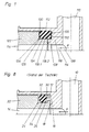
- Fig. 1
- Einen mit Fig. 8 vergleichbaren,abgebrochen zur Hälfte dargestellten zentralen Längsschnitt durch eine prinzipielle 1. Ausführungsform bei der mit einem Einspritzventil bestückten Abzweigung einer Kraftstoffzuleitung
- Fig. 2 und 3
- Je eine Fig. 1 entsprechende, aber ganz dargestellte Schnittansicht einer 2. bzw. 3. Ausführungsform
- Fig. 4
- Einen abgebrochen dargestellten zentralen Längsschnitt durch eine 4. Ausführungsform bei der Abzweigung einer Kraftstoffzuleitung, deren Wandung an der Abzweigstelle das Einspritzventil aufnimmt
- Fig. 5
- Eine den Fig. 2 und 3 entsprechende Schnittansicht einer 5. Ausführungsform in Explosionsdarstellung bei der Abzweigung einer Kraftstoffzuleitung in ein nicht dargestelltes Einspritzventil
- Fig. 6 und 7
- Der Fig. 5 entsprechende Schnittansichten einer 6. bzw. 7. Ausführungsform in Explosionsdarstellunggleichen Umfangs.
Der Einbauraum 120, der radial nach außen durch die Wandung der Abzweigung 112 mit kreiszylindrischer Ringfläche 130 koaxial zu den Ringflächen 126 und 128 begrenzt ist, nimmt ein rechteckig profiliertes elastomeres Dichtungselement 132 auf, das im Gegensatz zu der metallischen Zuleitung 110 mit Abzweigung 112 und dem metallischen Ventilgehäuse 122 zum Beispiel aus kraftstoffbeständigem Gummi besteht.
Dabei wurde der Raumfüllungsgrad so gewählt, daß das Dichtungselement 132 bei Montagetemperatur mit radialer Vorspannung auf den Ringflächen 126 und 128 sowie an der Innenfläche 130 anliegt. Sinkt die Betriebstemperatur unter die Montagetemperatur und kann die Quellung des Dichtungselementes unter Kraftstoffeinwirkung dessen durch Schrumpfung verminderte radial äußere Vorspannung nicht mehr aufrechterhalten, dann hebt das Dichtungselement 132 zwar von der Ringfläche 130 ab; gleichzeitig schrumpft das Dichtungselement 132 aber auf die Ringfläche 128 ebenso wie auf die Pingfläche 126 auf, wodurch der Spalt zwischen Sockel 116 und Ventilgehäuse 122 in beiden axialen Richtungen vollkommen sicher abgedichtet wird, weil das Dichtungselement 132 eine axial ausgedehnte, radial innere Dichtfläche 134 aufweist, die auf die zusätzliche, radial äußere Ringfläche 128 des Sockels übergreift und auf dieser den Einbauraum radial innen mitbegrenzenden Ringfläche 128 dichtend sitzt.
Die radiale Außenfläche 228 des Innenstutzens 236 bildet also hier die zusätzliche Ringfläche für den übergriff des Dichtungselementes 232.
Den Einbauraum zwischen der Abzweigung 312 radial außen und dem Adapter 346 sowie dem Zapfen 342 radial innen und axial zwischen der Wandung der Zuleitung 310 einerseits sowie dem Ventilgehäuse 322 andererseits ist ausgefüllt durch ein Dichtungselement 332, das radial innen eine mittlere Ringnut 350 zur Aufnahme der beiden Flansche 340 und 348 aufweist; die Flanken der Ringnut verklammern die beiden Flansche. Die radial innere Dichtfläche 334 ist also gestuft und liegt dichtend sowohl an der Ringfläche 326 des Zapfens 342 als auch an der zusätzlichen Ringfläche 328 des Adapters 346 an. Dabei ist der Durchmesser des Zapfens 342 etwas kleiner als der Durchmesser der Adapter-Ringfläche 328, während die Durchmesser der beiden Flansche 340 und 348 gleich sind.
Claims (8)
- Dichtungsanordnung für den Anschluß eines Ventils zur kraftstoffeinspritzung in Verbrennungsmotoren an eine Kraftstoffzuleitung (110), insbesondere Verteilerleitung für mehrere Einspritzventile; mit einem ringförmigen, elastomeren Dichtungselement (132), das in einem vom Ventil und einer Abzweigung (112, 116) der Leitung (110), oder dieser selbst, gemeinsam gebildeten Einbauraum (120) angeordnet ist und dabei einerseits an einer radial äußeren Ringfläche (126) des axial durchbohrten Ventilgehäuses (122) anliegt sowie andererseits an der koaxialen, radial inneren Ringfläche (130) der Abzweigung (112) oder Leitung (110) unter radialer Vorspannung anliegen soll, dadurch gekennzeichnet, daß das Dichtungselement (132) eine axial erstreckte radial innere Dichtfläche (134) aufweist, die auf eine zusätzliche, radial äußere Ringfläche (128) der Abzweigung (112, 116) oder Leitung, oder eines damit verbundenen Teiles (236; 346),übergreift und an dieser den axial begrenzten Einbauraum (120) radial innen mitbegrenzenden Ringfläche (128) dichtend anliegt; und daß sich die radialen Wärmeausdehnungs koeffizienten der unterschiedlichen Materialien des Dichtungselementes (132) einerseits bzw. des Ventilgehäuses (122) und der Abzweigung (112, 116) oder Leitung (110), oder des damit verbundenen Teiles (236; 346) andererseits so zueinander verhalten, daß das Dichtungselement (132) bei Abkühlung sowohl auf die Ringfläche (126) des Ventilgehäuses (122) als auch auf die zusätzliche Ringfläche (128) der Abzweigung (112, 116) oder Leitung, oder des damit verbundenen Teiles (236; 346) schrumpft.
- Dichtungsanordnung nach Anspruch 1, dadurch gekennzeichnet, daß die Profile des ringförmigen Einbauraumes (120) bzw. des Dichtungselementes (132) im wesentlichen rechteckig sind.
- Dichtungsanordnung nach Anspruch 1, dadurch gekennzeichnet, daß die Profile des ringförmigen Einbauraumes (220) bzw. des Dichtungselementes (232) im wesentlichen L-förmig und gegebenenfalls axial länger als radial dick sind.
- Dichtungsanordnung nach Anspruch 2 oder 3, dadurch gekennzeichnet, daß das Profil des Dichtungselementes (632; 732) radial innen oder außen eine Vertiefung (664; 764) oder Erhebung (662; 762) für den formschlüssigen Eingriff der Wandung der Abzweigung (612; 712) oder Leitung (610; 710) bzw. in diese aufweist.
- Dichtungsanordnung nach Anspruch 1, dadurch gekennzeichnet, daß das, das Ventilgehäuse (222) aufnehmende zylindrische Ende der Abzweigung (212) oder Leitung einen koaxialen Innenstutzen (236) aufweist, dessen radiale Außenfläche die zusätzliche Ringfläche (228) bildet.
- Dichtungsanordnung nach Anspruch 5, dadurch gekennzeichnet, daß der Innenstutzen (536) an seinem freien Ende einen radialen Außenwulst (556) für den formschlüssigen Eingriff in eine radial innere Ringnut (558) des Dichtungselementes (532) aufweist.
- Dichtungsanordnung nach Anspruch 3, dadurch gekennzeichnet, daß der Einbauraum (420) an der Abzweigstelle vollständig in der Wandung der Leitung (410) liegt.
- Dichtungsanordnung nach Anspruch 1, für ein Einspritzventil, dessen an die Kraftstoffzuleitung (310) oder deren Abzweigung (312) anzuschließendes Gehäuseende eine radial äußere Ringnut (344) mit der Geqenfläche (326) für den Sitz des Dichtungselementes (332) aufweist, dadurch gekennzeichnet daß das Profil des Dichtungselementes (332) im wesentlichen ein Rechteck ist mit radial innerer, axial mittiger Ringnut (350) zur Aufnahme zweier einander axial gegenüberstehender Flansche (340 und 348) zur axialen Begrenzung der Ringnut (349) des Ventilgehäuses (322) bzw. am freien Ende eines axial durchbohrten Adapters (346), der mit der Wandung der Leitung (310) kommuniziert und die zusätzliche Gegenfläche (328) zur Anlage der zusätzlichen Dichtfläche (335) des Dichtungselementes (322) bildet.
Applications Claiming Priority (3)
| Application Number | Priority Date | Filing Date | Title |
|---|---|---|---|
| DE4413863 | 1994-04-21 | ||
| DE4413863A DE4413863C2 (de) | 1994-04-21 | 1994-04-21 | Dichtungsanordnung für Einspritzventile an Kraftstoffzuleitungen |
| PCT/EP1995/001212 WO1995029336A1 (de) | 1994-04-21 | 1995-03-31 | Dichtungsanordnung für einspritzventile an kraftstoffzuleitungen |
Publications (2)
| Publication Number | Publication Date |
|---|---|
| EP0756669A1 EP0756669A1 (de) | 1997-02-05 |
| EP0756669B1 true EP0756669B1 (de) | 1998-01-07 |
Family
ID=6516034
Family Applications (1)
| Application Number | Title | Priority Date | Filing Date |
|---|---|---|---|
| EP95914336A Expired - Lifetime EP0756669B1 (de) | 1994-04-21 | 1995-03-31 | Dichtungsanordnung für einspritzventile an kraftstoffzuleitungen |
Country Status (4)
| Country | Link |
|---|---|
| US (1) | US5927726A (de) |
| EP (1) | EP0756669B1 (de) |
| DE (3) | DE4413863C2 (de) |
| WO (1) | WO1995029336A1 (de) |
Families Citing this family (11)
| Publication number | Priority date | Publication date | Assignee | Title |
|---|---|---|---|---|
| WO1997002427A1 (de) * | 1995-03-31 | 1997-01-23 | Parker Hannifin Gmbh | Kältefeste dichtungsanordnung für fahr- und flugzeuge, schiffe und maschinen |
| US6360898B1 (en) * | 2000-04-06 | 2002-03-26 | Harry L. Nurse, Jr. | Filtration device for a waste water treatment system |
| US7004476B2 (en) * | 2000-10-13 | 2006-02-28 | Nok Corporation | Combustion gas seal for injector |
| US6446582B1 (en) * | 2000-10-24 | 2002-09-10 | Robertshaw Controls Company | Fuel feedline and vapor barrier assembly |
| DE10108193A1 (de) * | 2001-02-21 | 2002-08-29 | Bosch Gmbh Robert | Befestigungsvorrichtung |
| DE10145035A1 (de) * | 2001-09-13 | 2003-04-10 | Bosch Gmbh Robert | Brennstoffeinspritzsystem |
| DE10208227A1 (de) * | 2002-02-26 | 2003-10-02 | Bosch Gmbh Robert | Brennstoffeinspritzanlage |
| DE102006013880A1 (de) * | 2006-03-25 | 2007-11-08 | Dr.Ing.H.C. F. Porsche Ag | Brennstoffeinspritzanlage |
| US7819382B2 (en) * | 2008-05-09 | 2010-10-26 | Gm Global Technology Operations, Inc. | Temperature and pressure responsive seal |
| JP5867158B2 (ja) * | 2012-02-24 | 2016-02-24 | Nok株式会社 | 密封構造 |
| DE102015216150A1 (de) | 2015-08-25 | 2017-03-02 | Volkswagen Aktiengesellschaft | Dichtungsanordnung für eine Kraftstoffzuleitung |
Family Cites Families (21)
| Publication number | Priority date | Publication date | Assignee | Title |
|---|---|---|---|---|
| US279087A (en) * | 1883-06-05 | Albeet h | ||
| GB191410973A (en) * | 1913-06-12 | 1915-09-02 | Hugo Junkers | Improvements in Means for Attaching Valve Casings to the Cylinders of Internal Combustion Engines. |
| US3190702A (en) * | 1961-05-23 | 1965-06-22 | Flick Reedy Corp | Sealing structure for piston and cylinder device |
| DE2208646C2 (de) * | 1972-02-24 | 1986-11-06 | Robert Bosch Gmbh, 7000 Stuttgart | Vorrichtung zur Befestigung elektromagnetischer Einspritzventile an gemischverdichtenden Brennkraftmaschinen |
| DE2233919C3 (de) * | 1972-07-10 | 1979-02-22 | Robert Bosch Gmbh, 7000 Stuttgart | Vorrichtung für eine Einspritzdüse zur Kraftstoffeinspritzung in den Saugkanal einer Brennkraftmaschine |
| US3802466A (en) * | 1972-08-03 | 1974-04-09 | Panella Ind Inc | Clean-out plug assembly |
| DE2242824C3 (de) * | 1972-08-31 | 1975-05-15 | Dr.-Ing.H.C. F. Porsche Ag, 7000 Stuttgart | Brennstoffeinspritzdüsenbefestigung |
| US3776209A (en) * | 1973-04-05 | 1973-12-04 | Bendix Corp | Fuel injector manifold and mounting arrangement |
| DE2824476C2 (de) * | 1978-06-03 | 1983-03-17 | Bayerische Motoren Werke AG, 8000 München | Brennstoffeinspritzdüsenbefestigung an einer Brennkraftmaschine |
| DE2827878A1 (de) * | 1978-06-24 | 1980-01-17 | Bosch Gmbh Robert | Kraftstoffeinspritzventil |
| JPS57108459A (en) * | 1980-12-24 | 1982-07-06 | Hitachi Ltd | Electronically controlled fuel injection system |
| IT1152184B (it) * | 1982-05-17 | 1986-12-31 | Alfa Romeo Auto Spa | Guaina di protezione per un iniettore di benzina |
| DE3304567A1 (de) * | 1983-02-10 | 1984-08-16 | Alfred Teves Gmbh, 6000 Frankfurt | Ausgleichsbehaelter |
| JPS59200061A (ja) * | 1983-04-25 | 1984-11-13 | Honda Motor Co Ltd | 燃料噴射装置 |
| CA1213803A (en) * | 1983-04-27 | 1986-11-12 | Honda Giken Kogyo Kabushiki Kaisha (Also Trading As Honda Motor Co., Ltd .) | Fuel injection system |
| DE3838914A1 (de) * | 1988-11-17 | 1990-05-23 | Bosch Gmbh Robert | Ventil |
| JPH0754616Y2 (ja) * | 1989-05-06 | 1995-12-18 | 臼井国際産業株式会社 | フユーエルデリバリパイプ |
| US5044340A (en) * | 1990-01-30 | 1991-09-03 | Siemens Automotive L.P. | Fuel injectors having adapter grommet |
| US5092300A (en) * | 1991-01-31 | 1992-03-03 | Siemens Automotive L.P. | Plastic fuel rail end joint |
| DE4329774A1 (de) * | 1993-09-03 | 1995-03-09 | Bosch Gmbh Robert | Vorrichtung zur Befestigung und Sicherung eines Ventils |
| EP0656494A1 (de) * | 1993-12-01 | 1995-06-07 | Du Pont De Nemours International S.A. | Elastomerdichtung |
-
1994
- 1994-04-21 DE DE4413863A patent/DE4413863C2/de not_active Expired - Fee Related
-
1995
- 1995-03-31 DE DE59501222T patent/DE59501222D1/de not_active Expired - Fee Related
- 1995-03-31 WO PCT/EP1995/001212 patent/WO1995029336A1/de not_active Ceased
- 1995-03-31 DE DE29514852U patent/DE29514852U1/de not_active Expired - Lifetime
- 1995-03-31 US US08/727,457 patent/US5927726A/en not_active Expired - Fee Related
- 1995-03-31 EP EP95914336A patent/EP0756669B1/de not_active Expired - Lifetime
Also Published As
| Publication number | Publication date |
|---|---|
| DE4413863C2 (de) | 1996-03-28 |
| EP0756669A1 (de) | 1997-02-05 |
| DE59501222D1 (de) | 1998-02-12 |
| US5927726A (en) | 1999-07-27 |
| WO1995029336A1 (de) | 1995-11-02 |
| DE29514852U1 (de) | 1995-12-14 |
| DE4413863A1 (de) | 1995-10-26 |
Similar Documents
| Publication | Publication Date | Title |
|---|---|---|
| EP3420255A1 (de) | Anschlussstutzen und wärmemanagementmodul mit einem solchen | |
| DE2208646C2 (de) | Vorrichtung zur Befestigung elektromagnetischer Einspritzventile an gemischverdichtenden Brennkraftmaschinen | |
| DE4413863C2 (de) | Dichtungsanordnung für Einspritzventile an Kraftstoffzuleitungen | |
| EP1965105B1 (de) | Dichtungsanordnung | |
| DE3421604C2 (de) | Anordnung einer Schlauchhülse an einem Kanalkörper eines Fluidaggregates | |
| EP0066704A1 (de) | Verbindungsstück zum Einbau in eine fluidführende Leitung, vorzugsweise zwischen ein Kunststoffrohr und ein Metallrohr | |
| DE10056005A1 (de) | Brennstoffeinspritzanlage | |
| EP3746692B1 (de) | Wasserleitung mit rohrfitting | |
| EP0428120A2 (de) | Trennbares Verbindungsstück für Rohrleitungen | |
| WO2004015263A1 (de) | Brennstoffeinspritzventil und verfahren zur montage eines brennstoffeinspritzventils in einer ventilaufnahme | |
| AT501851B1 (de) | Verbindung von leitungen für hochdruckmedien | |
| EP0836676B1 (de) | Kältefeste dichtungsanordnung für fahr- und flugzeuge, schiffe und maschinen | |
| EP0879377B1 (de) | Lösbare rohrverbindung für kunststoffrohre | |
| DE19807819C1 (de) | Verfahren zur brennraumseitigen Abdichtung eines Einspritzventils einer Brennkraftmaschine | |
| EP1751462B1 (de) | Lösbare ladeluft-kupplungsmuffe | |
| EP0971120B1 (de) | Anschlusselement einer Hochdruckleitung | |
| DE10106168A1 (de) | Brennstoffeinspritzventil und Verfahren zur Montage eines Brennstoffeinspritzventils in einer Ventilaufnahme | |
| EP0638719B1 (de) | Kraftstoffleitungsanschluss für Kraftstoffeinspritzpumpen | |
| DE102016011983A1 (de) | Kupplungsanordnung für Rohrleitungen | |
| DE202018101453U1 (de) | Dichtsystem | |
| DE102018002909A1 (de) | Anschlussadapter zum Anschluss einer Behandlungseinrichtung an einen Anschlusskopf einer Behandlungsvorrichtung für insbesondere flüssige Fluide, Anschlusskopf und Behandlungsvorrichtung | |
| DE19511537A1 (de) | Komponente für eine hydraulische oder pneumatische Anlage und für Fluide im allgemeinen, beispielsweise einen Hahn, ein Reihenfitting, ein Eckfitting, ein 3- oder Mehrwege-Fitting | |
| DE19932718A1 (de) | Steckkupplung | |
| EP1580409A2 (de) | Ölmodul | |
| DE202007007359U1 (de) | Temperiermittelanschluss für Temperiermittelkanäle von Werkzeugformen |
Legal Events
| Date | Code | Title | Description |
|---|---|---|---|
| PUAI | Public reference made under article 153(3) epc to a published international application that has entered the european phase |
Free format text: ORIGINAL CODE: 0009012 |
|
| 17P | Request for examination filed |
Effective date: 19961112 |
|
| AK | Designated contracting states |
Kind code of ref document: A1 Designated state(s): DE FR GB IT |
|
| RAP1 | Party data changed (applicant data changed or rights of an application transferred) |
Owner name: STREIT, GERHARD Owner name: KRUMEICH, PETER Owner name: ACHENBACH, MANFRED |
|
| RIN1 | Information on inventor provided before grant (corrected) |
Inventor name: STREIT, GERHARD Inventor name: KRUMEICH, PETER Inventor name: ACHENBACH, MANFRED |
|
| GRAG | Despatch of communication of intention to grant |
Free format text: ORIGINAL CODE: EPIDOS AGRA |
|
| 17Q | First examination report despatched |
Effective date: 19970430 |
|
| GRAG | Despatch of communication of intention to grant |
Free format text: ORIGINAL CODE: EPIDOS AGRA |
|
| GRAH | Despatch of communication of intention to grant a patent |
Free format text: ORIGINAL CODE: EPIDOS IGRA |
|
| GRAH | Despatch of communication of intention to grant a patent |
Free format text: ORIGINAL CODE: EPIDOS IGRA |
|
| GRAA | (expected) grant |
Free format text: ORIGINAL CODE: 0009210 |
|
| AK | Designated contracting states |
Kind code of ref document: B1 Designated state(s): DE FR GB IT |
|
| ITF | It: translation for a ep patent filed | ||
| REF | Corresponds to: |
Ref document number: 59501222 Country of ref document: DE Date of ref document: 19980212 |
|
| GBT | Gb: translation of ep patent filed (gb section 77(6)(a)/1977) |
Effective date: 19980210 |
|
| ET | Fr: translation filed | ||
| PLBQ | Unpublished change to opponent data |
Free format text: ORIGINAL CODE: EPIDOS OPPO |
|
| PLBI | Opposition filed |
Free format text: ORIGINAL CODE: 0009260 |
|
| PLBF | Reply of patent proprietor to notice(s) of opposition |
Free format text: ORIGINAL CODE: EPIDOS OBSO |
|
| 26 | Opposition filed |
Opponent name: CARL FREUDENBERG Effective date: 19981005 |
|
| PLBF | Reply of patent proprietor to notice(s) of opposition |
Free format text: ORIGINAL CODE: EPIDOS OBSO |
|
| PLBL | Opposition procedure terminated |
Free format text: ORIGINAL CODE: EPIDOS OPPC |
|
| PLBM | Termination of opposition procedure: date of legal effect published |
Free format text: ORIGINAL CODE: 0009276 |
|
| STAA | Information on the status of an ep patent application or granted ep patent |
Free format text: STATUS: OPPOSITION PROCEDURE CLOSED |
|
| 27C | Opposition proceedings terminated |
Effective date: 20001001 |
|
| REG | Reference to a national code |
Ref country code: GB Ref legal event code: IF02 |
|
| PGFP | Annual fee paid to national office [announced via postgrant information from national office to epo] |
Ref country code: FR Payment date: 20030327 Year of fee payment: 9 |
|
| PGFP | Annual fee paid to national office [announced via postgrant information from national office to epo] |
Ref country code: GB Payment date: 20030401 Year of fee payment: 9 |
|
| PG25 | Lapsed in a contracting state [announced via postgrant information from national office to epo] |
Ref country code: GB Free format text: LAPSE BECAUSE OF NON-PAYMENT OF DUE FEES Effective date: 20040331 |
|
| GBPC | Gb: european patent ceased through non-payment of renewal fee | ||
| PG25 | Lapsed in a contracting state [announced via postgrant information from national office to epo] |
Ref country code: FR Free format text: LAPSE BECAUSE OF NON-PAYMENT OF DUE FEES Effective date: 20041130 |
|
| REG | Reference to a national code |
Ref country code: FR Ref legal event code: ST |
|
| PG25 | Lapsed in a contracting state [announced via postgrant information from national office to epo] |
Ref country code: IT Free format text: LAPSE BECAUSE OF NON-PAYMENT OF DUE FEES Effective date: 20050331 |
|
| PGFP | Annual fee paid to national office [announced via postgrant information from national office to epo] |
Ref country code: DE Payment date: 20050426 Year of fee payment: 11 |
|
| PG25 | Lapsed in a contracting state [announced via postgrant information from national office to epo] |
Ref country code: DE Free format text: LAPSE BECAUSE OF NON-PAYMENT OF DUE FEES Effective date: 20061003 |