EP0756358B1 - Artikelzuführung - Google Patents
Artikelzuführung Download PDFInfo
- Publication number
- EP0756358B1 EP0756358B1 EP19950111725 EP95111725A EP0756358B1 EP 0756358 B1 EP0756358 B1 EP 0756358B1 EP 19950111725 EP19950111725 EP 19950111725 EP 95111725 A EP95111725 A EP 95111725A EP 0756358 B1 EP0756358 B1 EP 0756358B1
- Authority
- EP
- European Patent Office
- Prior art keywords
- casings
- casing
- feed
- transport
- housing
- Prior art date
- Legal status (The legal status is an assumption and is not a legal conclusion. Google has not performed a legal analysis and makes no representation as to the accuracy of the status listed.)
- Expired - Lifetime
Links
Images

Classifications
-
- H—ELECTRICITY
- H01—ELECTRIC ELEMENTS
- H01R—ELECTRICALLY-CONDUCTIVE CONNECTIONS; STRUCTURAL ASSOCIATIONS OF A PLURALITY OF MUTUALLY-INSULATED ELECTRICAL CONNECTING ELEMENTS; COUPLING DEVICES; CURRENT COLLECTORS
- H01R43/00—Apparatus or processes specially adapted for manufacturing, assembling, maintaining, or repairing of line connectors or current collectors or for joining electric conductors
- H01R43/01—Apparatus or processes specially adapted for manufacturing, assembling, maintaining, or repairing of line connectors or current collectors or for joining electric conductors for connecting unstripped conductors to contact members having insulation cutting edges
Definitions
- the invention relates to a device for feeding with plugs, in particular Insulation displacement contact elements, equipped housings (so-called articles) to a cable assembly machine for the automatic Manufacture of cable sets, with a plurality in parallel next to each other arranged feed channels, above which are located in vertical storage devices held magazines for the housing, and one Position handling system for the transport of the housing to a housing workpiece carrier, the - equipped with housings - a processing station the cable assembly machine can be fed to make contact.
- From DE 42 33 561 A1 is also a device for cable assembly of cables with a housing module for feeding Housings in housing workpiece carriers known.
- the housings are in Receiving trays arranged, taken up by vertical storage devices and are unloaded via feed channels.
- One the work cycle corresponding number of housings to be machined is via a corresponding number of feed channels by means of a position handling system fed a housing workpiece carrier and with this from the Conveyed housing module to a processing station for plugging the cables.
- the invention is based on this prior art, the task of leaving the principle of removing the housing from a spool and proposing an article feed with magazine holder for the housing, which in all areas, such as magazine loading and emptying, transport and positioning of the housing and the drive is simplified in such a way that processing of any desired assembly variants is possible without machine downtimes or with short changeover times.
- the object is achieved in that the housing in Contacting layer are arranged one behind the other in housing receiving rods, the vertically extending block magazines that can be refilled one above the other are stacked and in associated feed channels by means of an ejection device are emptied that the housing in front of the transport direction Feed channels a transverse displacement device for the housing workpiece carrier is provided, depending on the travel position from the feed channels Housing of the same and / or different number of poles by means of a Transfer device can be introduced in the contact position, and that for the position constant Further transport of the assembled housing workpiece carrier to Processing station a transport device is provided.
- the receiving rods are stackable one above the other, preferably at the end in Falling rails held open plastic tubes of rectangular cross-section, whose profile is essentially adapted to the outer contour of the housing and the one on its end opposite the removal side with a Securing, in particular an inner projection, against falling out of the housing are provided.
- Several support rods are used to form one Block magazine connected to each other, in particular glued. This will achieved the advantage over the use of individual pick-up rods, that loading and unloading of the vertical storage for the block magazines is much easier and a cyclical update of the Pick-up rods in the unloading position by means of a laterally arranged Clock facility is enabled.
- a central extension unit is provided for the entire device, with the each of the receiving rods located in the unloading plane on their rear End is detected by means of a slide which is in the receiving rod located housing in the direction of emptying by a central, reversible drive loaded.
- the slider can be advantageous on one Spiral spring rod can be arranged between two transport rollers on the one side and two pressure rollers mounted on the opposite side is, the pressure rollers are designed as a rocker such that they are dependent optionally by actuation by a double actuation cylinder can be applied to the coil spring rod, from the powerless zero position initiation of a feed or retreat non-positive connection of the spiral spring rod with one of the transport rollers to effect.
- the transport rollers are with interlocking wheels for Provided for the purpose of reversing operation.
- the vertical storage devices, feed channels and the transverse displacement device for the housing workpiece carrier on both sides symmetrical to To arrange the longitudinal axis of the processing station of the cable assembly machine and the article feed for an opposite one Cable assembly with a 180 ° turning device for the housing to equip one side.
- the 180 ° turning device consists of a arranged parallel to the feed channel with which ensures will that regardless of their position in the magazine Plane of symmetry identically directed housing of the processing station in mutually opposite processing position are fed to the to be able to contact both ends of a line.
- each receiving rod in the vertical storage device in the respective unloading position in the unloading plane is coaxial with the receiving rod the feed channel arranged as the housing buffer for receiving a plurality of housings is formed one behind the other and one Buffer module that ensures the maintenance of the article feed, if a housing mounting rod is empty and the following one Pick-up rod must be brought into position via a clock device.
- the buffer module has a removable protruding into the feed channel Stop on the by means of an actuating cylinder in a release position is spendable. Furthermore, the buffer module has an insertion element linear transport of one or more housings in the housing workpiece carrier on. The insert element can have a loading slide adjustable point of engagement with respect to the housing, which over a pneumatic central drive coordinated with the stop actuation connected is.
- the transverse displacement device for the housing workpiece carrier with which the various Housing feed lines, namely the feed channels, can optionally be approached are.
- the transverse displacement device preferably consists of a A rail with a housing carriage that runs over it electrically controlled stepper motor is driven and positionally accurate Inclusion of housings in front of the feed channels is movable.
- the preferred Embodiments are on each side of the longitudinal axis of the processing station four different housing feed lines can be approached, one positioning system with indexing of the slide in the housing feed lines exact transition of the article treads guaranteed.
- the loaded housing workpiece carriers are transported further with a Transport device to the processing station of the cable assembly machine instead of.
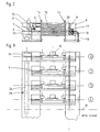
- the cable assembly machine shown in Fig. 1 of the drawing shows schematically a processing station 1 with a turning tongs 2, which of individual conductors are fed into the rear from a supply of cables the processing station on both sides after cutting to length with so-called Articles, i.e. housings equipped with insulation displacement contact elements, be contacted.
- the feeding of the housing to the processing station 1 takes place with the article feeder 3 shown on the right in the drawing both sides of the processing station for the purpose of providing IDC contact elements for opposing processing of any assembly variants supplied on both ends of the conductor. All Article feed drives are centrally located in a control cabinet 4.
- the article feeder 3 rests on a machine frame 5 and consists of essentially from a vertical storage device 6, which are arranged one above the other Includes receiving rods 7, in which housings in a row Contacting position are arranged, as well as devices 8 for gradual emptying the receiving rods 7 in feed channels 9.
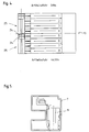
- the article feeder 3 is designed to in the processing station 1 both ends of the delivered there Lines with insulation displacement contact elements in opposite processing to contact. 4 of the drawing, while Fig. 3 of the drawing is a plan view of the left side of the Article feed shows, with the inscription "Mitte System" clarifies is that a similar training of the article feed also on the right Plane of symmetry 10 is provided.
- each housing 11 When the article is fed, the individual housings 11 are in principle Contacting layer arranged one behind the other in the housing mounting rods 7, which have a length of about 800mm and are essentially in profile Outer contour of the housing (see. Fig. 5 of the drawing) are adapted. On the The end face facing the emptying device 8 can be found in each receiving rod 7 a safeguard against falling out of the housing in the form of a internal projection, not shown, or an attachable plug strip.
- Each six housing receiving rods 7 are to form a vertical block magazine 12 glued together and constitute a handling unit
- the block magazines 12 are in turn in lateral guides 13, 14 Type of drop rails arranged one above the other and intermittently by means of a Clock mechanism 15 can be lowered into the emptying level E.
- the left article feeder as a whole has four such vertical storage devices, wherein it should be noted that according to Fig. 4 of the drawing also the article feed is constructed in the same way on the right.
- the following is therefore an example only structure and function of a vertical storage device with emptying and Further transport of the housing described, but it is by itself understands that these devices on each vertical storage device, ie are present a total of eight times in the described embodiment. Drive and control are combined into units.
- the device for emptying 8 also called extension unit, intended.
- This consists of a central drive, which is connected to one another toothed transport rollers 16 and pressure rollers 17 arranged above them a spiral spring rod 18 guided in between acts at its front end a slide 19 is attached.
- the slide 19 is from behind in the housing receiving rod 7 introduced and presses on the line of one after the other arranged housing 11 for the purpose of extending on the opposite Page in the feed channel 9.
- the Pressure rollers 17 are mounted on a rocker in such a way that they are dependent from actuation by a double actuation cylinder 20 optionally the coil spring rod 18 can be applied to the powerless zero position initiation of a feed or retreat non-positive connection of the spiral spring rod 18 with one of the to effect driven transport rollers 16.
- the housing can be controlled individually or in cycles in the control Feed channel 9 are advanced.
- a removable stop 21 for providing a buffer for the purpose arranged to minimize tool life.
- the stop 21 cooperates with an insertion element 22, which is used to fill the front of the feed channel 9 positioned housing workpiece carrier 23 one or more housings in the Pushes in the workpiece carrier, the during Stop 21 releases the feeder.
- the housing workpiece carrier 23 is on a housing receiving slide 24 arranged, which is part of a transverse displacement device 25, which is in the transport direction the housing is arranged in front of the feed channels and enables depending on the travel position from the feed channels housing same and / or different number of poles by means of the extension unit 8 in the contact position.
- the housing receiving carriage 24 is open a rail 26 movable by means of a positioning system for starting the four different housing feed lines according to FIG. 3 of the drawing designed. The drive takes place in a precise position via one in the drawing not recognizable electrically controlled stepper motor.
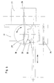
- Fig. 6 shows details of the 180 ° turning device 27 in a plan view, on the the housing workpiece carrier 23 can be seen on the right, from the center of the latter Channel 28, the housing 11 in a coaxial channel 29 of a turning plate 30 can be shifted, the 180 ° back and forth in one according to the arrow Storage 31 is rotatable.
- the housing thus turned in the contact position 11 are then moved by an axially movable driver 32 in Extendable pins 33 detected and into a not shown Item carrier spent.
- the driver 32 also detects the in the Busbar 34 of the right bar arranged housing 11 in symmetrical way for further transport.
- a transport device is used for the processing station 1.
Landscapes
- Engineering & Computer Science (AREA)
- Manufacturing & Machinery (AREA)
- Automatic Assembly (AREA)
- Warehouses Or Storage Devices (AREA)
Description
- Fig. 1
- eine Gesamt-Seitenansicht einer Kabelkonfektioniermaschine mit erfindungsgemäßer Artikelzufuhr in Seitenansicht,
- Fig. 2
- die Artikelzuführung links der Kabelkonfektioniermaschine der Fig. 1 schematisch in einer Seitenansicht,
- Fig. 3
- die Artikelzuführung der Fig. 2 in Draufsicht,
- Fig. 4
- die Artikelzuführung links und rechts in Draufsicht,
- Fig. 5
- eine Gehäuse-Aufnahmestange in Stirnansicht und
- Fig. 6
- eine Wendevorrichtung in Draufsicht.
- 1
- Bearbeitungsstation
- 2
- Wendezange
- 3
- Artikelzuführung
- 4
- Schaltschrank
- 5
- Maschinengestell
- 6
- Vertikalspeicheinrichtung
- 7
- Aufnahmestangen
- 8
- Einrichtung zur Entleerung
- 9
- Zuführkanäle
- 10
- Symmetrieebene
- 1 1
- Gehäuse
- 12
- Blockmagazin
- 13
- seitliche Führung
- 14
- seitliche Führung
- 1 5
- Taktmechanismus
- 16
- Transportrolle
- 17
- Andruckrolle
- 18
- Spiralfederstange
- 19
- Schieber
- 20
- Doppelbetätigungszylinder
- 21
- Anschlag
- 22
- Einschubelement
- 23
- Gehäuse-Werkstückträger
- 24
- Gehäuse-Aufnahmeschlitten
- 25
- Quer-Verfahreinrichtung
- 26
- Schiene
- 27
- 180°-Wendevorrichtung
- 28
- Kanal
- 29
- Kanal
- 30
- Wendeteller
- 31
- Lagerung
- 32
- Mitnehmer
- 33
- Stifte
- 34
- Sammelschiene
Claims (19)
- Vorrichtung zur Zuführung von mit Steckern, insbesondere Schneidklemmkontaktelementen, ausgerüsteten Gehäusen (11) zu einer Kabelkonfektioniermaschine für die automatische Herstellung von Leitungssätzen, mit einer Mehrzahl parallel nebeneinander angeordneter Zuführkanäle (9), über denen sich in Vertikalspeichereinrichtungen (6) gehaltene Magazine (12) für die Gehäuse (11) befinden, und mit einem Positionshandhabungssystem für den Transport der Gehäuse (11) zu einem Gehäuse-Werkstückträger (23), der - bestückt mit Gehäusen - einer Bearbeitungsstation (1) der Kabelkonfektioniermaschine zum Kontaktieren zuführbar ist,
dadurch gekennzeichnet,
daß die Gehäuse (11) in Kontaktierlage hintereinander in Gehäuseaufnahmestangen (7) angeordnet sind, die übereinander zu nachführbaren, vertikal sich erstreckenden Blockmagazinen (12) gestapelt sind und in dazugehörige Zuführkanäle (9) mittels einer Ausschubeinrichtung (8) entleerbar sind, daß in Transportrichtung der Gehäuse (11) vor den Zuführkanälen (9) eine Quer-Verfahreinrichtung (25) für den Gehäuse-Werkstückträger (23) vorgesehen ist, in den in Abhängigkeit von der Verfahrposition aus den Zuführkanälen (9) Gehäuse (11) mittels einer Übergabeeinrichtung (22) in Kontaktierlage einbringbar sind, und daß für den lagekonstanten Weitertransport des bestückten Gehäuse-Werkstückträgers (23) zur Bearbeitungsstation (1) eine Transporteinrichtung vorgesehen ist. - Vorrichtung nach Anspruch 1, dadurch gekennzeichnet, daß die Gehäuse-Aufnahmestangen (7) übereinander stapelbare, endseitig in Fallschienen (13, 14) gehaltene, offene Kunststoffröhren rechteckigen Querschnitts sind, deren Profil im wesentlichen an die Außenkontur der Gehäuse (11) angepaßt ist und die an ihrer der Entnahmeseite gegenüberliegenden Stirnseite mit einer Sicherung, insbesondere einem Innenvorsprung, gegen Herausfallen der Gehäuse (11) versehen sind.
- Vorrichtung nach Anspruch 2, dadurch gekennzeichnet, daß die Gehäuse-Aufnahmestangen (7) zur Bildung des Blockmagazins (12) miteinander verklebt sind.
- Vorrichtung nach einem der Ansprüche 1 bis 3, dadurch gekennzeichnet, daß die Vertikalspeichereinrichtung (6) für die Blockmagazine (12) mit einer Takteinrichtung (15) für eine taktweise Nachführung der Gehäuse-Aufnahmestangen (7) in die Endladeposition versehen ist.
- Vorrichtung nach einem der Ansprüche 1 bis 4, dadurch gekennzeichnet, daß vier bis acht Gehäuse-Aufnahmestangen (7) zur einem Blockmagazin (12) zusammengefaßt sind.
- Vorrichtung nach einem der Ansprüche 1 bis 5, dadurch gekennzeichnet, daß fünf Aufnahmestangen ein Blockmagazin bilden.
- Vorrichtung nach einem der Ansprüche 1 bis 6, dadurch gekennzeichnet, daß vier oder mehr Vertikalspeicher (6) parallel zueinander vor der Querverfahreinrichtung (25) angeordnet sind.
- Vorrichtung nach einem der Ansprüche 1 bis 7, dadurch gekennzeichnet, daß eine zentrale Ausschubeinheit (8) vorgesehen ist, mit der jede in einer Entladeebene (E) befindliche Gehäuse-Aufnahmestange (7) an ihrem rückwärtigen Ende mittels eines Schiebers (19) erfaßbar ist, der die Gehäuse (11) in Entleerungsrichtung durch einen zentralen, reversierfähigen Antrieb belastet.
- Vorrichtung nach Anspruch 8, dadurch gekennzeichnet, daß der Schieber (19) an einer Spiralfederstange (18) angeordnet ist, die zwischen zwei miteinander verzahnten Transportrollen (16) auf der einen Seite und zwei Andruckrollen (17) auf der gegenüberliegenden Seite gelagert ist, wobei die Andruckrollen (17) als Wippe derart ausgebildet sind, daß sie in Abhängigkeit von der Betätigung durch einen Doppelbetätigungszylinder (20) wahlweise an die Spiralfederstange (18) anlegbar sind, um aus der kraftlosen Nullposition heraus die Initiierung eines Vorschubs oder eines Rückzugs durch kraftschlüssige Verbindung der Spiralfederstange (18) mit einer der Transportrollen (16) zu bewirken.
- Vorrichtung nach einem der Ansprüche 8 und 9, dadurch gekennzeichnet, daß der Antrieb pneumatisch über Elektromagnetventile angesteuert ist.
- Vorrichtung nach einem der Ansprüche 1 bis 10, dadurch gekennzeichnet, daß vor jeder in der Vertikalspeichereinrichtung (6) befindlichen Gehäuse-Aufnahmestange (7) in der jeweiligen Entladeposition in einer Entladeebene (E) koaxial zu der Gehäuse-Aufnahmestange (7) der Zuführkanal (9) angeordnet ist, der als Gehäusepuffer zur Aufnahme einer Mehrzahl von Gehäusen (11) hintereinander ausgebildet ist und einen Puffermodul bildet.
- Vorrichtung nach Anspruch 11, dadurch gekennzeichnet, daß der Puffermodul einen in den Zuführkanal (9) hineinragenden entfernbaren Anschlag (21) aufweist, der mittels eines Betätigungszylinders in eine Freigabeposition verbringbar ist, wobei der Puffermodul ein Einschubelement (22) zum linearen Transport eines oder mehrerer Gehäuse (11) in dem Gehäusewerkstückträger (23), vorzugsweise in Form eines erstellbaren Ladeschiebers, aufweist.
- Vorrichtung nach Anspruch 12, dadurch gekennzeichnet, daß die Quer-Verfahreinrichtung (25) für den Gehäuse-Werkstückträger (23) aus einer Schiene (26) mit darauf geführten Gehäuse-Aufnahmeschlitten (24) besteht, der über einen elektrisch gesteuerten Schrittmotor angetrieben ist.
- Vorrichtung nach einem der Ansprüche 1 bis 13, dadurch gekennzeichnet, daß die Transporteinrichtung für den Weitertransport der bestückten Gehäuse-Werkstückträger (23) aus einer Hubeinrichtung zwecks Anheben auf die Bearbeitungsebene und einer Rastertransporteinrichtung besteht.
- Vorrichtung nach einem der Ansprüche 1 bis 14, dadurch gekennzeichnet, daß die Vertikalspeichereinrichtungen (6), die Zuführkanäle (9) und die Quer-Verfahreinrichtung (25) sowie Vorrichtungen zum Weitertransport beiderseits symmetrisch zur Längsachse der Bearbeitungsstation der Kabelkonfektioniermaschine angeordnet sind und daß die Artikelzufuhr für eine gegenüberliegende Kabelkonfektionierung mit einer 180°-Wendevorrichtung für die Gehäuse (11) auf der einen Seite ausgerüstet ist.
- Vorrichtung nach Anspruch 15, dadurch gekennzeichnet, daß die 180°-Wendevorrichtung aus einem parallel zu dem Zuführkanal (9) angeordneten Wendeteller (30) besteht, der mit einer Längsführung (29) zur Aufnahme der dem Gehäuse-Werkstückträger (23) entnommenen Gehäuse (11) versehen und um 180° drehbar gelagert ist.
- Vorrichtung nach Anspruch 16, dadurch gekennzeichnet, daß zur Entnahme der Gehäuse (11) ein in Artikelzuführungsrichtung verschiebarer Mitnehmer (32) vorgesehen ist.
- Vorrichtung nach Anspruch 17, gekennzeichnet durch einen Artikelpositionierer für den Ausgleich des durch die 180° Wendung der Gehäuse verursachten Mittenversatzes.
- Vorrichtung nach einem der Ansprüche 15 bis 18, dadurch gekennzeichnet, daß bei der Quer-Verfahreinrichtung (25) für die beidseitige Verarbeitung die beiden Gehäuse-Aufnahmeschlitten (24) gekoppelt sind und ein gleichzeitiges Zuführen von Artikeln auf beiden Zuführseiten durchführen.
Priority Applications (2)
| Application Number | Priority Date | Filing Date | Title |
|---|---|---|---|
| EP19950111725 EP0756358B1 (de) | 1995-07-26 | 1995-07-26 | Artikelzuführung |
| DE59504912T DE59504912D1 (de) | 1995-07-26 | 1995-07-26 | Artikelzuführung |
Applications Claiming Priority (1)
| Application Number | Priority Date | Filing Date | Title |
|---|---|---|---|
| EP19950111725 EP0756358B1 (de) | 1995-07-26 | 1995-07-26 | Artikelzuführung |
Publications (2)
| Publication Number | Publication Date |
|---|---|
| EP0756358A1 EP0756358A1 (de) | 1997-01-29 |
| EP0756358B1 true EP0756358B1 (de) | 1999-01-20 |
Family
ID=8219465
Family Applications (1)
| Application Number | Title | Priority Date | Filing Date |
|---|---|---|---|
| EP19950111725 Expired - Lifetime EP0756358B1 (de) | 1995-07-26 | 1995-07-26 | Artikelzuführung |
Country Status (2)
| Country | Link |
|---|---|
| EP (1) | EP0756358B1 (de) |
| DE (1) | DE59504912D1 (de) |
Families Citing this family (2)
| Publication number | Priority date | Publication date | Assignee | Title |
|---|---|---|---|---|
| CN112582188B (zh) * | 2019-09-11 | 2025-07-15 | 珠海格力新元电子有限公司 | 电容器外壳的输送设备 |
| CN118989168A (zh) * | 2024-10-11 | 2024-11-22 | 丽水驰达五金箱包有限公司 | 一种箱包锁加工的锁料加工取料一体化设备 |
Family Cites Families (3)
| Publication number | Priority date | Publication date | Assignee | Title |
|---|---|---|---|---|
| US4653665A (en) * | 1984-02-27 | 1987-03-31 | Molex Incorporated | Connector cassette and feed system |
| DE4233561A1 (de) | 1992-09-30 | 1994-03-31 | Siemens Ag | Vorrichtung zur Kabelkonfektionierung (Gehäusezufuhr) |
| DE4342386C1 (de) * | 1993-12-11 | 1995-02-23 | Matthias Hoffmeier | Verfahren und Vorrichtung zum Konfektionieren von TAE-Steckern |
-
1995
- 1995-07-26 DE DE59504912T patent/DE59504912D1/de not_active Expired - Fee Related
- 1995-07-26 EP EP19950111725 patent/EP0756358B1/de not_active Expired - Lifetime
Also Published As
| Publication number | Publication date |
|---|---|
| DE59504912D1 (de) | 1999-03-04 |
| EP0756358A1 (de) | 1997-01-29 |
Similar Documents
| Publication | Publication Date | Title |
|---|---|---|
| DE1602951C3 (de) | Mehrspindel-Bohrmaschine | |
| EP3218126B1 (de) | Beschickungsvorrichtung und biegepresse und anordnung einer biegepresse und einer daran gekoppelten beschickungsvorrichtung und verfahren zum beschicken einer biegepresse | |
| DE2500710A1 (de) | Automatische spulenhalterbaugruppe zum magnetbandtransfer | |
| DE3141784C2 (de) | Vorrichtung zum Zu- und Wegführen von Statoren elektrischer Maschinen | |
| DE4201289C2 (de) | Vorrichtung zur Handhabung von Werkstücken | |
| WO2016109862A1 (de) | Beschickungsvorrichtung für eine biegepresse | |
| DE2610002B2 (de) | Vorrichtung zum Einsetzen eines Spulenpaares und eines Magnetbandes in eine Kassettengehäusehälfte zum Zwecke des Zusammenbaus einer Magnetbandkassette | |
| DE69217204T2 (de) | Bandkassettenzufuhreinheit für automatischen Vorrichtungen | |
| DE2313417B2 (de) | Vorrichtung zum Herstellen von verdrallten Leitungsdrahtpaaren und Verfahren zum Verdrallen von Leitungsdrahtpaaren | |
| DE69413503T2 (de) | Allzweckbearbeitungsmaschine für Anschlussdrähte | |
| DE3877607T2 (de) | Einrichtung zum sortieren und lagern elektrischer kabel. | |
| DE68916205T2 (de) | Automatischer Lademechanismus. | |
| DE3878003T2 (de) | Einrichtung fuer die herstellung von elektrischen kabelanordnungen. | |
| DE3018628C2 (de) | Vorrichtung zum automatischen Aufwickeln von Stranggut, insbesondere von Draht | |
| EP0628648B1 (de) | Vorrichtung zum Bestücken der Spulendorne eines Spulengatters | |
| DE3434883A1 (de) | Einsetzvorrichtung fuer elektronische bauteile | |
| EP0756358A1 (de) | Artikelzuführung | |
| EP1089932B1 (de) | Anlegevorrichtung | |
| DE3811435A1 (de) | Verbinderblockzufuehrstation und kabelbaumauswurfstation | |
| DE3344483A1 (de) | Einrichtung zum be- und entladen von bearbeitungseinrichtungen fuer leiterplatten, insbesondere bauelemente-bestueckeinrichtungen | |
| DE102022119016A1 (de) | Kontaktladeanordnung für eine Elektrische-Steckverbinder-Montagemaschine | |
| EP1100164B1 (de) | Artikelzuführung | |
| EP0773611B1 (de) | Transporteinrichtung für eine Kabelkonfektioniermaschine | |
| DE3707412C2 (de) | ||
| EP0802589B1 (de) | Vorrichtung zur Kabelkonfektionierung von Flachbandleitern |
Legal Events
| Date | Code | Title | Description |
|---|---|---|---|
| PUAI | Public reference made under article 153(3) epc to a published international application that has entered the european phase |
Free format text: ORIGINAL CODE: 0009012 |
|
| 17P | Request for examination filed |
Effective date: 19960213 |
|
| AK | Designated contracting states |
Kind code of ref document: A1 Designated state(s): BE DE FR GB IT NL |
|
| RBV | Designated contracting states (corrected) |
Designated state(s): BE DE FR GB IT NL |
|
| GRAG | Despatch of communication of intention to grant |
Free format text: ORIGINAL CODE: EPIDOS AGRA |
|
| GRAG | Despatch of communication of intention to grant |
Free format text: ORIGINAL CODE: EPIDOS AGRA |
|
| GRAH | Despatch of communication of intention to grant a patent |
Free format text: ORIGINAL CODE: EPIDOS IGRA |
|
| 17Q | First examination report despatched |
Effective date: 19980602 |
|
| GRAH | Despatch of communication of intention to grant a patent |
Free format text: ORIGINAL CODE: EPIDOS IGRA |
|
| GRAA | (expected) grant |
Free format text: ORIGINAL CODE: 0009210 |
|
| AK | Designated contracting states |
Kind code of ref document: B1 Designated state(s): BE DE FR GB IT NL |
|
| ET | Fr: translation filed | ||
| GBT | Gb: translation of ep patent filed (gb section 77(6)(a)/1977) |
Effective date: 19990204 |
|
| REF | Corresponds to: |
Ref document number: 59504912 Country of ref document: DE Date of ref document: 19990304 |
|
| ITF | It: translation for a ep patent filed | ||
| PLBE | No opposition filed within time limit |
Free format text: ORIGINAL CODE: 0009261 |
|
| STAA | Information on the status of an ep patent application or granted ep patent |
Free format text: STATUS: NO OPPOSITION FILED WITHIN TIME LIMIT |
|
| 26N | No opposition filed | ||
| PGFP | Annual fee paid to national office [announced via postgrant information from national office to epo] |
Ref country code: GB Payment date: 20010614 Year of fee payment: 7 |
|
| PGFP | Annual fee paid to national office [announced via postgrant information from national office to epo] |
Ref country code: FR Payment date: 20010709 Year of fee payment: 7 |
|
| PGFP | Annual fee paid to national office [announced via postgrant information from national office to epo] |
Ref country code: BE Payment date: 20010713 Year of fee payment: 7 |
|
| PGFP | Annual fee paid to national office [announced via postgrant information from national office to epo] |
Ref country code: NL Payment date: 20010717 Year of fee payment: 7 |
|
| PGFP | Annual fee paid to national office [announced via postgrant information from national office to epo] |
Ref country code: DE Payment date: 20010913 Year of fee payment: 7 |
|
| REG | Reference to a national code |
Ref country code: GB Ref legal event code: IF02 |
|
| PG25 | Lapsed in a contracting state [announced via postgrant information from national office to epo] |
Ref country code: GB Free format text: LAPSE BECAUSE OF NON-PAYMENT OF DUE FEES Effective date: 20020726 |
|
| PG25 | Lapsed in a contracting state [announced via postgrant information from national office to epo] |
Ref country code: BE Free format text: LAPSE BECAUSE OF NON-PAYMENT OF DUE FEES Effective date: 20020731 |
|
| BERE | Be: lapsed |
Owner name: STOCKO METALLWARENFABRIKEN *HENKELS UND SOHN G.M.B Effective date: 20020731 |
|
| PG25 | Lapsed in a contracting state [announced via postgrant information from national office to epo] |
Ref country code: NL Free format text: LAPSE BECAUSE OF NON-PAYMENT OF DUE FEES Effective date: 20030201 Ref country code: DE Free format text: LAPSE BECAUSE OF NON-PAYMENT OF DUE FEES Effective date: 20030201 |
|
| GBPC | Gb: european patent ceased through non-payment of renewal fee |
Effective date: 20020726 |
|
| PG25 | Lapsed in a contracting state [announced via postgrant information from national office to epo] |
Ref country code: FR Free format text: LAPSE BECAUSE OF NON-PAYMENT OF DUE FEES Effective date: 20030331 |
|
| NLV4 | Nl: lapsed or anulled due to non-payment of the annual fee |
Effective date: 20030201 |
|
| REG | Reference to a national code |
Ref country code: FR Ref legal event code: ST |
|
| PG25 | Lapsed in a contracting state [announced via postgrant information from national office to epo] |
Ref country code: IT Free format text: LAPSE BECAUSE OF NON-PAYMENT OF DUE FEES;WARNING: LAPSES OF ITALIAN PATENTS WITH EFFECTIVE DATE BEFORE 2007 MAY HAVE OCCURRED AT ANY TIME BEFORE 2007. THE CORRECT EFFECTIVE DATE MAY BE DIFFERENT FROM THE ONE RECORDED. Effective date: 20050726 |