EP0755028B1 - Anordnung mit einer elektronischen Handfrankiermaschine - Google Patents
Anordnung mit einer elektronischen Handfrankiermaschine Download PDFInfo
- Publication number
- EP0755028B1 EP0755028B1 EP96107736A EP96107736A EP0755028B1 EP 0755028 B1 EP0755028 B1 EP 0755028B1 EP 96107736 A EP96107736 A EP 96107736A EP 96107736 A EP96107736 A EP 96107736A EP 0755028 B1 EP0755028 B1 EP 0755028B1
- Authority
- EP
- European Patent Office
- Prior art keywords
- arrangement according
- wheels
- ink
- print head
- franking machine
- Prior art date
- Legal status (The legal status is an assumption and is not a legal conclusion. Google has not performed a legal analysis and makes no representation as to the accuracy of the status listed.)
- Expired - Lifetime
Links
- 238000004140 cleaning Methods 0.000 claims description 37
- 238000007789 sealing Methods 0.000 claims description 23
- 238000003032 molecular docking Methods 0.000 claims description 6
- 230000008878 coupling Effects 0.000 claims description 5
- 238000010168 coupling process Methods 0.000 claims description 5
- 238000005859 coupling reaction Methods 0.000 claims description 5
- 241000282472 Canis lupus familiaris Species 0.000 claims 2
- 230000001360 synchronised effect Effects 0.000 claims 2
- 230000005540 biological transmission Effects 0.000 claims 1
- 238000007639 printing Methods 0.000 description 12
- 230000006835 compression Effects 0.000 description 9
- 238000007906 compression Methods 0.000 description 9
- 230000008929 regeneration Effects 0.000 description 6
- 238000011069 regeneration method Methods 0.000 description 6
- 238000007641 inkjet printing Methods 0.000 description 4
- 125000006850 spacer group Chemical group 0.000 description 4
- 238000000034 method Methods 0.000 description 3
- 230000003287 optical effect Effects 0.000 description 3
- 230000000694 effects Effects 0.000 description 2
- 239000012528 membrane Substances 0.000 description 2
- 230000001960 triggered effect Effects 0.000 description 2
- IHIDFKLAWYPTKB-UHFFFAOYSA-N 1,3-dichloro-2-(4-chlorophenyl)benzene Chemical compound C1=CC(Cl)=CC=C1C1=C(Cl)C=CC=C1Cl IHIDFKLAWYPTKB-UHFFFAOYSA-N 0.000 description 1
- HLQDGCWIOSOMDP-UHFFFAOYSA-N 2,3,4,5-tetrachlorobiphenyl Chemical compound ClC1=C(Cl)C(Cl)=CC(C=2C=CC=CC=2)=C1Cl HLQDGCWIOSOMDP-UHFFFAOYSA-N 0.000 description 1
- 230000002745 absorbent Effects 0.000 description 1
- 239000002250 absorbent Substances 0.000 description 1
- OJIJEKBXJYRIBZ-UHFFFAOYSA-N cadmium nickel Chemical compound [Ni].[Cd] OJIJEKBXJYRIBZ-UHFFFAOYSA-N 0.000 description 1
- 239000000969 carrier Substances 0.000 description 1
- 239000003795 chemical substances by application Substances 0.000 description 1
- 238000013479 data entry Methods 0.000 description 1
- 230000018044 dehydration Effects 0.000 description 1
- 238000006297 dehydration reaction Methods 0.000 description 1
- 238000001514 detection method Methods 0.000 description 1
- 238000000605 extraction Methods 0.000 description 1
- 239000000835 fiber Substances 0.000 description 1
- 238000009499 grossing Methods 0.000 description 1
- 238000002372 labelling Methods 0.000 description 1
- 238000011022 operating instruction Methods 0.000 description 1
- 239000000523 sample Substances 0.000 description 1
- 239000000725 suspension Substances 0.000 description 1
Images






Classifications
-
- B—PERFORMING OPERATIONS; TRANSPORTING
- B41—PRINTING; LINING MACHINES; TYPEWRITERS; STAMPS
- B41J—TYPEWRITERS; SELECTIVE PRINTING MECHANISMS, i.e. MECHANISMS PRINTING OTHERWISE THAN FROM A FORME; CORRECTION OF TYPOGRAPHICAL ERRORS
- B41J2/00—Typewriters or selective printing mechanisms characterised by the printing or marking process for which they are designed
- B41J2/005—Typewriters or selective printing mechanisms characterised by the printing or marking process for which they are designed characterised by bringing liquid or particles selectively into contact with a printing material
- B41J2/01—Ink jet
- B41J2/135—Nozzles
- B41J2/165—Prevention or detection of nozzle clogging, e.g. cleaning, capping or moistening for nozzles
- B41J2/16585—Prevention or detection of nozzle clogging, e.g. cleaning, capping or moistening for nozzles for paper-width or non-reciprocating print heads
-
- B—PERFORMING OPERATIONS; TRANSPORTING
- B41—PRINTING; LINING MACHINES; TYPEWRITERS; STAMPS
- B41J—TYPEWRITERS; SELECTIVE PRINTING MECHANISMS, i.e. MECHANISMS PRINTING OTHERWISE THAN FROM A FORME; CORRECTION OF TYPOGRAPHICAL ERRORS
- B41J2/00—Typewriters or selective printing mechanisms characterised by the printing or marking process for which they are designed
- B41J2/005—Typewriters or selective printing mechanisms characterised by the printing or marking process for which they are designed characterised by bringing liquid or particles selectively into contact with a printing material
- B41J2/01—Ink jet
- B41J2/135—Nozzles
- B41J2/165—Prevention or detection of nozzle clogging, e.g. cleaning, capping or moistening for nozzles
- B41J2/16517—Cleaning of print head nozzles
-
- B—PERFORMING OPERATIONS; TRANSPORTING
- B41—PRINTING; LINING MACHINES; TYPEWRITERS; STAMPS
- B41J—TYPEWRITERS; SELECTIVE PRINTING MECHANISMS, i.e. MECHANISMS PRINTING OTHERWISE THAN FROM A FORME; CORRECTION OF TYPOGRAPHICAL ERRORS
- B41J3/00—Typewriters or selective printing or marking mechanisms characterised by the purpose for which they are constructed
- B41J3/36—Typewriters or selective printing or marking mechanisms characterised by the purpose for which they are constructed for portability, i.e. hand-held printers or laptop printers
-
- G—PHYSICS
- G07—CHECKING-DEVICES
- G07B—TICKET-ISSUING APPARATUS; FARE-REGISTERING APPARATUS; FRANKING APPARATUS
- G07B17/00—Franking apparatus
- G07B17/00016—Relations between apparatus, e.g. franking machine at customer or apparatus at post office, in a franking system
- G07B17/0008—Communication details outside or between apparatus
-
- G—PHYSICS
- G07—CHECKING-DEVICES
- G07B—TICKET-ISSUING APPARATUS; FARE-REGISTERING APPARATUS; FRANKING APPARATUS
- G07B17/00—Franking apparatus
- G07B17/00185—Details internally of apparatus in a franking system, e.g. franking machine at customer or apparatus at post office
- G07B17/00193—Constructional details of apparatus in a franking system
-
- G—PHYSICS
- G07—CHECKING-DEVICES
- G07B—TICKET-ISSUING APPARATUS; FARE-REGISTERING APPARATUS; FRANKING APPARATUS
- G07B17/00—Franking apparatus
- G07B17/00459—Details relating to mailpieces in a franking system
- G07B17/00508—Printing or attaching on mailpieces
-
- G—PHYSICS
- G07—CHECKING-DEVICES
- G07B—TICKET-ISSUING APPARATUS; FARE-REGISTERING APPARATUS; FRANKING APPARATUS
- G07B17/00—Franking apparatus
- G07B17/00016—Relations between apparatus, e.g. franking machine at customer or apparatus at post office, in a franking system
- G07B17/0008—Communication details outside or between apparatus
- G07B2017/00153—Communication details outside or between apparatus for sending information
- G07B2017/00177—Communication details outside or between apparatus for sending information from a portable device, e.g. a card or a PCMCIA
-
- G—PHYSICS
- G07—CHECKING-DEVICES
- G07B—TICKET-ISSUING APPARATUS; FARE-REGISTERING APPARATUS; FRANKING APPARATUS
- G07B17/00—Franking apparatus
- G07B17/00185—Details internally of apparatus in a franking system, e.g. franking machine at customer or apparatus at post office
- G07B17/00193—Constructional details of apparatus in a franking system
- G07B2017/00217—Portable franking apparatus, i.e. the whole franking apparatus, not parts alone
-
- G—PHYSICS
- G07—CHECKING-DEVICES
- G07B—TICKET-ISSUING APPARATUS; FARE-REGISTERING APPARATUS; FRANKING APPARATUS
- G07B17/00—Franking apparatus
- G07B17/00185—Details internally of apparatus in a franking system, e.g. franking machine at customer or apparatus at post office
- G07B17/00314—Communication within apparatus, personal computer [PC] system, or server, e.g. between printhead and central unit in a franking machine
- G07B2017/00346—Power handling, e.g. power-down routine
-
- G—PHYSICS
- G07—CHECKING-DEVICES
- G07B—TICKET-ISSUING APPARATUS; FARE-REGISTERING APPARATUS; FRANKING APPARATUS
- G07B17/00—Franking apparatus
- G07B17/00459—Details relating to mailpieces in a franking system
- G07B17/00508—Printing or attaching on mailpieces
- G07B2017/00516—Details of printing apparatus
- G07B2017/00524—Printheads
- G07B2017/00532—Inkjet
Definitions
- the invention relates to an arrangement for an electronic hand franking machine with an ink print head and with integrated means for Control and supply of the ink printhead.
- Such a franking machine can be used advantageously anywhere where there is only a small amount of mail, but the desire for there is a modern franking imprint.
- the mechanical forerunner of such a franking machine is the D2 franking machine from Francotyp-Postalia GmbH, which has been tried and tested over many decades.
- This franking machine works without prepaid cards, so that the user has to make a fee payment at the post office and there the post office official sets the default system in the machine accordingly and seals it with a seal, see operating instructions.
- a franking strip dispenser system is known, see WO92 / 07338 A1, with which a date, a postage value and an advertising slogan are printed on a franking strip.
- a printing unit, a processor system, a read / write device, an operating device and a strip storage container are arranged in a common housing.
- the reader / writer is used to hold the postage credit cards and is connected to the processor system via information lines for the exchange of digitized data for the identification of billing and the individual advertising clichés stored on the postage credit card.
- the digitized data of the advertising slogan as well as control and security data are also transmitted between the processor system and the printing unit via information and signal lines.
- the system can be operated independently of the mains by means of batteries or rechargeable accumulators. For this system, the batteries have to provide the energy for both the printing unit and the drive of the strip roll, so they must be sufficiently powerful, otherwise the operating time is restricted.
- the strip storage container requires an appropriate volume. Due to the use of postage credit cards, there is no need to load the franking machines at the post office. However, the franking strips must be glued to the postal items and must be such that they cannot be reused or reused.
- the pattern of the postage free stamp is composed of successive partial patterns.
- the Frankier contains an electronic control device for the inkjet printing device and their control sequence, a clock circuit for Clocking of the logic circuit in the course of printing and a Postage memory.
- the franking machine is one with its own Power supply stored microcomputer provided its clock circuit is operated by a detector device.
- the detector device serves the relative speed of the franking machine to determine against the mail item and as control signals of the To supply clock circuit.
- the clock circuit generates proportional to Relative speed clock signals for the logic circuit of the microcomputer.
- the ink jet printing device gives the successively respective partial pattern of the postage free stamp in time with these clock signals when the franker is moved over the mail item.
- Two parallel axes with two each serve to facilitate movement Guide rollers at the ends.
- In the inkjet printer are eleven nozzles in a row transverse to the direction of movement of the franking machine arranged.
- the detector device is constructed as an optical monitor.
- a source of light in the form of a light emitting diode is on the area of Focused recording medium in which the ink droplets from the Inkjet printing device are ejected. That reflected Light is received by an optical probe made of fibers Photo transistor supplied.
- the microcomputer is programmed so that a Ink droplet is ejected every time the printing device is operated. This enables continuous optical scanning is a tax model in addition to the actual franking imprint created in the form of a line that underlines the former. The monitor feels this line off.
- the photo transistor responds to changes in Pressure point to the free area of this control line and generates a pulsating Signal that is given to the microcomputer and its Frequency of the moving speed of the monitor over the Control line is determined.
- a rechargeable nickel-cadmium battery is used for the power supply.
- the housing of the franking machine is - except for the nozzle exit surface closed a cap that corresponds to the stroke of a
- the operating switch can only be moved by an authorized one Person can be removed. This takes place in a postage distribution center, when the stored postage is largely used up.
- the meter contains a number of input connections, all of them are accessible when the cap is removed. These input connections consist of two sockets connected to the microcomputer are also two sockets from the input of the power supply Possibility to connect to a charging source and finally a docking device for the ink tank.
- the franking machine After removing the cap, the franking machine is moved to a central location that has a main input connector that connects to a charger for the power supply, an ink supply and a postage calculator connected is. So the battery becomes in one operation Reloaded, additional postage bought into the storage register entered the microcomputer and the ink tank filled.
- the determination of the relative speed by means of Differences between light and dark on the record carrier depend on of the color of the recording medium - dark - or less - bright - prone to failure.
- a sealing device which has a cover pad, moved by means of a holder with the ink print head.
- the sealing device is means of covering the entire range of motion of the ink print head extending rocker and one the bracket placed dome part from the outside into the nozzle exit surface sealing or releasing position can be moved.
- the Nozzle surface has a protruding collar, inside this the sealing device is lowered. In this way becomes a capillary effective and fill up with ink from the nozzles- the cavity formed.
- a carriage with the ink printheads becomes a recording area driven into a regeneration and cleaning area.
- the Movement brushes the nozzle surface against an elastic wiper lip over and is roughly cleaned in this way.
- the regeneration area is a regeneration device with a cover to the Ink printhead docked with each row of nozzles respectively each ink printing module - with multi-color heads - covered separately becomes.
- the regeneration device works with a suction pump. By Vacuum removes ink, ink residue and air bubbles. Also this solution is specially tailored for an office printer.
- a hand franking machine with docking station for reloading a battery is known from GB-A-2 247 376.
- the purpose of the invention is to increase the reliability and the Field of application of hand franking machines with ink printheads.
- the invention is based, for an electronic task Hand franking machine to find a solution that meets the modern Requirements for franking and cliché printing are sufficient and for one Regeneration - recharge of postage, battery and ink - in one central facility, such as the post office, is eliminated.
- the hand franking machine according to the arrangement according to the invention is by operation with a data entry means such as one Postage credit card, protected against manipulation; besides is also an additional sealing is possible.
- a data entry means such as one Postage credit card, protected against manipulation; besides is also an additional sealing is possible.
- a data entry means such as one Postage credit card, protected against manipulation; besides is also an additional sealing is possible.
- Options for entering data into a franking machine are shown here not further discussed, but referred to EP 0 566 225 A2.
- the combination of an ink printhead with a replaceable one Ink tank, cleaning part and sealing cap as well as rechargeable battery with charging connection and optional modem with access to one Teleporto data center the user has it in hand, his Always keep the hand franking machine ready for operation.
- Attaching the ink printhead to a lever that is in one Area between two stops is resilient and with a Spacer nose slides on the record carrier, secures constantly a constant distance between the nozzle openings and the Recording medium.
- the provided centrifugal brake prevents the maximum permitted travel speed.
- the housing of the hand franking machine resilient on the chassis stored and also ergonomically designed is one elastic operation possible.
- the ink printhead is cleaned by ejecting ink the writing nozzles and / or suction of ink into the sealing cap in the Adapter, the ink from the Sealing cap is sucked into a suction tank.
- the cleaning process can usually be limited to the time in the printing breaks become.
- the wiper lip is used in a manner known per se for rough cleaning Die face.
- the resilient mounting of the sealing cap with the associated one Guiding them in the housing of the adapter secures one Always defined position between ink print head and sealing cap and adequate tightness.
- the combination of the stop edge, Guide strips with bevels and counter spring in the housing of the Adapter and stop on the support lever for the ink printhead achieved a good locking in the end position.
- the first assembly 2 is an electronic hand franking machine a housing 1, a first assembly 2 and a second assembly 3.
- the second assembly 3 is on the first assembly placed and both together are arranged in the housing 1.
- the adapter 6 is discussed in more detail below.
- a spring 226 is used for the resilient mounting of the housing 1 on the Chassis 22.
- the ink print head 21 is connected to the second circuit board 32 connected for this purpose with a Connector 322 is provided.
- the third circuit board 33 is connected via a connecting cable 332 to the second circuit board 32 connected for this purpose with a further connector 323 is provided.
- the ink print head 21 attached to a lever 227.
- the lever 227 is about an axis 228 swiveling and spring-loaded.
- the lever 227 detects one Driver nose 2274 directed downwards for one in adapter 6 cleaning carriage 621 located.
- a front wheel 223 On the front axle 221, a front wheel 223 is mounted, which as a roller Friction wheel is designed with an incremental encoder 2232, to which the sensor 311 is assigned. So that the driving speed regardless of the nature of the record carrier 5 detected and the ink printhead 21 by the microprocessor 320th be controlled accordingly.
- the drive wheels 2231 can be integrally formed on the front wheel 223.
- the rear wheels 2251 can be integrally formed on the rear wheel 225.
- a stop 19 is formed in the housing 1, on which the spring 226 is non-positively.
- the spring 226, on the other hand, is on the chassis frame 220 attached. In this way, the housing 1 is rotatable resiliently mounted about the axis 221 on the chassis 22. On the Representation of a lock with possible sealing waived.
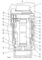
- FIG. 4 shows clearly how the rear wheels 225 in the direction of travel are placed inside. As a result, when the Hand franking machine over the same record carrier in Transverse direction is tightened.
- the lever 227 pivotable about the axis 228 has a stop lug 2272 and a stop lug 2273.
- the Stop 2272 is hook-shaped and engages behind one Edge of the chassis frame 220.
- the stop lug 2273 is for Bottom of the chassis frame 220 directed.
- a spring 229 is in close to the pivot point of the lever 227 attached to the latter and lies non-positively on the bottom of the chassis frame 220.
- the stop lug 2272 comes into contact with the already called edge of the chassis frame 220.
- the stop lug 2273 then has its maximum distance to the bottom of the chassis frame 220. This distance also becomes - according to the lever distance - The maximum swivel range for the ink print head 21st certainly. If the hand franking machine on the record carrier 5 is placed, the lever 227 by the spacer 2271 pressed against the action of the spring 229. End position is when the stop lug 2273 bears against the chassis frame.
- connection from the ink tank 213 is still over the ink hose 215 to the supply channel 216 and to an ink channel 217 of the ink print head 21 can be seen.
- the ink pressure chambers are omitted for simplicity.
- the sectional view also shows the connection 2141 on the ink print head 21 for the connecting cable 214 and the axle 2241 for the clutch wheels 224 recognizable.
- the clutch wheels 224 are on the axle 2241 rigidly attached, which again in the chassis frame 220 is rotatably mounted.
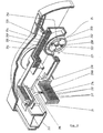
- FIG. 6 show details of a centrifugal brake 25 and further details of the ink print head 21.
- the centrifugal brake 25 is mounted on the front axle 221 and in built up in a known manner.
- the housing 251 is in the chassis frame 220 molded.
- the centrifugal brake 25 consists of a first brake shoes 252 mounted on an axle 253 together with associated stop 258, one mounted on an axis 256 second brake shoes 255 together with the associated stop 259 and two Compression springs 254, 257.
- the compression spring 254 is between the stop 259 and one leg of the brake shoe 252 arranged so that the latter by the spring force with his other leg against the Stop 258 is pressed.
- the analog is between the stop 258 and one leg of the brake shoes 255, the compression spring 257 is arranged, so that the brake shoe 255 with its other leg is pressed against the stop 259. If one is exceeded permissible maximum speed are those on the brake shoes 252, 255 acting centrifugal forces greater than the spring forces, causing the Press brake shoes 252, 255 against the wall of housing 251 and brake the hand franking machine.
- the sectional view of the ink print head 21 allows the ink flow via connection 2108 for ink hose 215 from the ink tank Recognize 213.
- the ink initially flows into the supply channel 216 and from there via the ink channels 217 to the nozzle openings 212.
- Figure 8 shows the structure of the adapter 6.
- the adapter 6 is in essentially divided into two areas. A first area for that Docking of the ink printhead 21 and a second area for the electrical coupling of the hand franking machine.
- the first area contains a cleaning device 62 with a Wiper lip 620, a sealing cap 6210, a suction pump 623 and a suction tank 624.
- the second area includes a battery charger 610, one External connection socket 611 for network and data, if necessary a not modem shown and a connector 616 for electrical Connection - battery supply, control data exchange - with the Manual franking machine.
- the cleaning device 62 has a cleaning carriage 621 and a receiving part 622 for the former.
- the receiving part 622 is in one Not specified recess in the housing 60 of the adapter 6 used.
- the cleaning carriage 621 includes those formed at its ends Guide hook 6212 the guide strips 62201, which on the Side walls 6220 of the receiving part 622 are integrally formed.
- the Guide strips 62201 are designed so that the Cleaning sled 621 both sliding on it undergoes a height adjustment as well as in the end positions defined stop.
- the guide strips are 62201 at the ends with step stops 62202, bevels 62203 and pin-shaped end stops 62204.
- the cleaning carriage 621 has one at one end plate-shaped stop 6211 and one from this protruding pin 6213.
- the stop 6211 serves as a driver, when the hand franking machine is inserted into the adapter 6.
- the pin 6213 serves as a receptacle for a compression spring 625, the the other end sits on a pin 603.
- the pin 603 is on Housing 60 of the adapter 6 integrally formed.
- the sealing cap 6210 contains a circumferential seal 62101, a Suction pad 62102, which has a groove 62103.
- the groove 62103 serves to cause a row of nozzles when the ink print head 21 is docked exposed. With several rows of nozzles, there would be a corresponding amount of grooves be provided.
- the sealing cap is over a connection piece 62104 and a hose 6233 with the suction channel 6231 in the housing 6230 of the suction pump 623 and thus connected to the latter, see also Figure 9.
- the suction pump 623 works with a membrane 6232. Es could also use any other suction pump become.
- the housing 6230 sits directly on the suction tank 624 and is flanged to it.
- the control of the suction pump 623 takes place via a connecting cable 614, which with the circuit board 61 and Control electronics not shown is connected.
- a connecting cable 614 On the Printed circuit board 61 is also attached to a connector 615, of which once a connection cable 612 to the external connection socket 611 and on the other hand a connecting cable 613 to the plug 616 for the Hand franking machine goes.
- the cleaning procedure is done by corresponding actuation of the keys 15 of the hand franking machine triggered.
- the housing 60 of the adapter 6 is trough-shaped in its upper part designed by pulling up the sidewalls 601. So that will a first pre-positioning for the hand franking machine to be put down reached. Then another precise guidance of the same achieve, there are still guide rails 602 on the side walls 601 on which the hand franking machine with its slide rails 13 is performed.
- FIG. 9 shows the state in which the Hand franking machine with its driver nose 2274 on lever 227 comes into engagement with the stop 6211 on the cleaning carriage 621.
- the pin 6213 presses against the Compression spring 625
- the cleaning carriage 621 slides with its Guide hook 6212
- the charging and control connection 313 is on the plug 616 pushed.
- the contact forces are larger than that Restoring force of the compression spring 625, so that the hand franking machine in this position remains stable, especially since the suction forces act between seal 62101 and nozzle surface.
- Another A solution would be possible with an additional snap-in connection.
- FIG 10 the relationships between hand franking and Adapter 6 shown with full docking.
- the Cleaning carriage 621 lies here with its guide hook 6212 on the straight part of the guide strip 62201 and on the End stops 62204.
- the sealing cap 6210 lies with the seal 62101 non-positively on the nozzle plane of the ink print head 21.
- the charging and control connection 313 is completely on the plug 616 pushed.
- the outer part of the postage credit card 4 projects into the Pocket 604 of housing 60.
- ink is transferred from the ink tank 213 over the Ink hose 215 sucked into the ink print head 21 and arrives here first in the supply channel 216. From the Supply channel 216 becomes ink through ink channels 217 and not Ink pressure chambers to the nozzle openings 212 shown in more detail. directed. The jetted ink hits the suction pad 62102, penetrates the same and then passes through hose 6233 to Suction pump 623 and from this into the suction tank 624.
- FIG. 11 The perspective view with an angular section according to FIG. 11 is used for illustrative support for the representation according to FIG. 10.
Landscapes
- Physics & Mathematics (AREA)
- General Physics & Mathematics (AREA)
- Engineering & Computer Science (AREA)
- Computer Security & Cryptography (AREA)
- Ink Jet (AREA)
- Devices For Checking Fares Or Tickets At Control Points (AREA)
- Accessory Devices And Overall Control Thereof (AREA)
Description
Es ist andererseits ein Frankierstreifengeber-System bekannt, siehe WO92/07338 A1, mit dem auf einen Frankierstreifen ein Datum, ein Portowert und ein Werbeklischee gedruckt wird. In einem gemeinsamen Gehäuse sind ein Druckwerk, ein Prozessorsystem, eine Lese-Schreibeinrichtung, eine Bedienvorrichtung und ein Streifenvorratsbehälter angeordnet. Die Lese-Schreibeinrichtung dient zur Aufnahme der Portokreditkarten und ist mit dem Prozessorsystem über Informationsleitungen zum Austausch digitalisierter Daten der Identifizierung der Gebührenverrechnung und des auf der Portokreditkarte gespeicherten individuellen Werbeklischees verbunden. Zwischen dem Prozessorsystem und dem Druckwerk werden die digitalisierten Daten des Werbeklischees sowie Kontroll- und Sicherungsdaten gleichfalls über Informations- und Signalleitungen übertragen. Das System ist netzunabhängig mittels Batterien oder aufladbarer Akkumulatoren betreibbar. Für dieses System müssen die Batterien die Energie sowohl für das Druckwerk als auch für den Antrieb der Streifenrolle liefern, demzufolge ausreichend leistungsstark sein, weil anderenfalls die Bedienzeit eingeschränkt wird. Der Streifenvorratsbehälter erfordert ein entsprechendes Volumen. Auf Grund der Verwendung von Portokreditkarten entfällt ein Laden der Frankiermaschinen bei der Post. Allerdings müssen die Frankierstreifen auf das Postgut geklebt werden und so beschaffen sein, daß eine Wieder- oder Weiterverwendung ausgeschlossen ist.
- Fig. 1
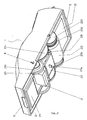
- Eine Explosivdarstellung einer elektronischen Handfrankiermaschine mit Adapter,
- Fig. 2
- eine perspektivische Ansicht der Handfrankiermaschine von unten,
- Fig. 3
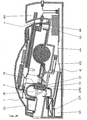
- eine Längsansicht mit Schnitt durch das Gehäuse der Handfrankiermaschine,
- Fig. 4
- eine Draufsicht auf das Fahrgestell bei teilweise weggeschnittenem Gehäuse der Handfrankiermaschine,
- Fig. 5
- eine perspektivische Ansicht auf einen Längsschnitt im Bereich des Tintenversorgungskanals,
- Fig. 6
- perspektivische Teilschnittansichten zum Tintendruckkopf und der Fliehkraftbremse,
- Fig. 7
- eine perspektivische Ansicht der Handfrankiermaschine von unten bei einem Längsschnitt im Bereich des Inkrementalgebers,
- Fig. 8
- eine perspektivische Ansicht auf einen Längsschnitt durch den Adapter im Bereich des Absaugkanals und Details zur Dichtkappe,
- Fig. 9
- einen Längsschnitt durch die Handfrankiermaschine und den Adapter vor dem Andocken,
- Fig. 10
- einen Längsschnitt durch die Handfrankiermaschine und den Adapter im angedockten Zustand
- Fig. 11
- eine perspektivische Ansicht mit Winkelschnitt durch die Handfrankiermaschine nach Fig. 10.
- Einen Schlitz 10 zur Einführung einer Portokreditkarte 4,
- Öffnungen 11 für eine Vorderachse 221,
- Bedientasten 15,
- eine Öffnung 16 für ein Display,
- eine Öffnung 17 für einen Ladeanschluß,
- eine vordere und eine hintere Führungsmarke 12 sowie
- eine Aufsetzmarke 18 für die Frankierung.
- einem Tintendruckkopf 21 und einem zugehörigen Tintentank 213 einschließlich dem zugeordneten Verbindungsschlauch 215,
- einem Fahrgestell 22 mit einem Fahrgestellrahmen 220, einer Vorderachse 221 mit zwei Antriebsrädern 2231, zwei Kupplungsrädern 224, zwei Hinterachsen 222 mit je einem Hinterrad 225 und je einem Abtriebsrad 2251.
- eine erste Leiterkarte 31 mit einer Schreib-Leseeinrichtung 310 sowie zugehöriger Portokreditkarten-Aufnahme 3101, einem Sensor 311 zur Geschwindigkeitserfassung und einem Lade- sowie wahlweisem Datenanschluß 313,
- eine zweite Leiterkarte 32 mit einem Mikroprozessor 320 und einer nachladbaren Batterie 321,
- eine dritte Leiterkarte 33 mit einem Display 330 und Schaltelementen 331.
- 1
- Gehäuse der Handfrankiermaschine
- 10
- Schlitz für Portokreditkarte 4
- 11
- Öffnung für Vorderachse 221
- 12
- vordere beziehungsweise hintere Führungsmarke zur Frankierung
- 13
- Gleitschiene
- 15
- Bedientasten
- 16
- Öffnung für Display
- 17
- Öffnung für Ladeanschluß
- 18
- Aufsetzmarke für Frankierung
- 19
- Anschlag für Feder 226
- 2
- erste Baugruppe
- 21
- Tintendruckkopf
- 210
- Gehäuse des Tintendruckkopfes 21
- 2108
- Anschluß für Tintenschlauch 215
- 212
- Düsenöffnung
- 2120
- Düsenreihe
- 213
- Tintentank, auswechselbar
- 214
- Verbindungskabel vom Tintendruckkopf 21 zur zweiten Leiterplatte 32
- 2141
- Anschluß für Verbindungskabel 214
- 215
- Tintenschlauch vom Tintentank 213 zum Tintendruckkopf 21
- 216
- Versorgungskanal im Tintendruckkopf 21
- 217
- Tintenkanal im Tintendruckkopf 21
- 22
- Fahrgestell
- 220
- Fahrgestellrahmen
- 221
- Vorderachse
- 222
- Hinterachse
- 223
- Vorderrad
- 2231
- Antriebsrad
- 2232
- Inkrementalgeber
- 224
- Kupplungsrad
- 2241
- Achse des Kupplungsrades 224
- 225
- Hinterrad
- 2251
- Abtriebsrad
- 226
- Feder zwischen Fahrgestellrahmen 220 und Gehäuse 1
- 227
- schwenkbarer Hebel zur Tintendruckkopf-Aufhängung
- 2271
- Abstandsnase am Hebel 227
- 2272
- Anschlagnase am Hebel 227 für unteren Anschlag
- 2273
- Anschlagnase am Hebel 227 für oberen Anschlag
- 2274
- Mitnehmernase am Hebel 227 für Reinigungsschlitten 621
- 228
- Achse für Hebel 227
- 229
- Feder für Hebel 227
- 25
- Fliehkraftbremse
- 251
- Gehäuse für Fliehkraftbremse 25
- 252
- erster Bremsbacken
- 253
- Achse für Bremsbacken 252
- 254
- Druckfeder für Bremsbacken 252
- 255
- zweiter Bremsbacken
- 256
- Achse für Bremsbacken 255
- 257
- Druckfeder für Bremsbacken 255
- 258
- Anschlag für Bremsbacken 252
- 259
- Anschlag für Bremsbacken 255
- 3
- zweite Baugruppe
- 31
- erste Leiterkarte
- 310
- Lese-Schreibeinrichtung
- 3101
- Portokreditkarten-Aufnahme
- 311
- Sensor für Inkrementalgeber 2232
- 312
- Verbindungskabel zur zweiten Leiterplatte 32
- 313
- Lade- und Steueranschluß
- 32
- zweite Leiterkarte
- 320
- Steuerelektronik, Mikroprozessor
- 321
- Batterie, nachladbar
- 322
- Steckverbinder für Verbindungskabel 312 und 214
- 323
- Steckverbinder für Verbindungskabel 332
- 33
- dritte Leiterkarte
- 330
- Display
- 331
- Schaltelemente
- 332
- Verbindungskabel zur zweiten Leiterkarte 32
- 4
- Portokreditkarte
- 5
- Aufzeichnungsträger, Postgut
- 6
- Adapter
- 60
- Gehäuse des Adapters 6
- 601
- Seitenwand des Gehäuses 60
- 602
- Führungsschiene auf der Seitenwand 601
- 603
- Zapfen für Druckfeder 625
- 604
- Tasche in Gehäuse 60 für Portokreditkarte 4
- 61
- Leiterkarte
- 610
- Batterieladevorrichtung
- 611
- Außenanschlußbuchse für Netz und Daten
- 612
- Verbindungskabel von der Außenanschlußbuchse 611 zur Leiterkarte 61
- 613
- Verbindungskabel von der Leiterkarte 61 zum Stecker 615 beziehungsweise zur Handfrankiermaschine
- 614
- Verbindungskabel von der Leiterkarte 61 zur Reinigungsvorrichtung 62 beziehungsweise zur Saugpumpe 623
- 615
- Steckverbinder für Verbindungskabel 612
- 616
- Stecker für Handfrankiermaschine
- 62
- Reinigungsvorrichtung
- 620
- Wischlippe
- 621
- Reinigungsschlitten
- 6210
- Dichtkappe
- 62101
- Dichtung in der Dichtkappe 6210
- 62102
- Saugkissen in der Dichtkappe 6210
- 62103
- Nut in Saugkissen 62102
- 62104
- Anschlußstutzen an der Dichtkappe 6210 für Schlauch 6233
- 6211
- Anschlag am Reinigungsschlitten 621
- 6212
- Führungshaken am Reinigungsschlitten 621
- 6213
- Zapfen am Reinigungsschlitten 621
- 622
- Aufnahmeteil für Reinigungsschlitten 621
- 6220
- Seitenwand des Aufnahmeteils 622
- 62201
- Führungsstreifen für Führungshaken 6212
- 62202
- Anschlag in Führungsstreifen 6220
- 62203
- Schräge im Führungsstreifen 62201
- 62204
- Endanschlag in Führungsstreifen 62201
- 623
- Saugpumpe
- 6230
- Gehäuse der Saugpumpe 623
- 6231
- Saugkanal im Gehäuse 6230
- 6232
- Membran im Gehäuse 6230
- 6233
- Schlauch von der Saugpumpe 623 zur Dichtkappe 6210
- 624
- Absaugtank
- 625
- Druckfeder
Claims (20)
- Anordnung mit
einer elektronischen Handfrankiermaschine mit einem Tintendruckkopf mit integrierten Mitteln zur Steuerung und Versorgung des Tintendruckkopfes, wobei in einem Gehäuse (1) der Handfrankiermaschine eine erste Baugruppe (2) aus einem Fahrgestell (22) und einem Tintendruckkopf (21) mit einem auswechselbaren Tintentank (213) und eine zweite Baugruppe (3) aus mindestens einem Dateneingabemittel für die Nachkreditierung, einer Steuerelektronik sowie einer nachladbaren Batterie (321) mit Ladeanschluß (313) angeordnet sind, und
einem Adapter (6) mit Netz- und bedarfsweise Datenanschluß (611) vorgesehen ist, der eine Batterieladevorrichtung (610) aufweist, dadurch gekennzeichnet, daß der Adapter (6) eine Reinigungsvorrichtung (62) aufweist und als Ablage- und Andockstation für die Handfrankiermaschine zum Nachladen der Batterie und zum Reinigen und Abdichten des Tintendruckkopfes ausgebildet ist. - Anordnung nach Anspruch 1, dadurch gekennzeichnet, daß das Fahrgestell (22) einen steifen Fahrgestellrahmen (220) mit einer in diesem drehbeweglich gelagerten Vorderachse (221) und mindestens einer in diesem wahlweise starr oder drehbeweglich gelagerten Hinterachse (222) sowie an den Achsen (221, 222) befestigten Rädern (223, 225) aufweist und
daß der Fahrgestellrahmen (220) mit der Vorderachse (221) in das Gehäuse (1) eingehängt ist und beide zueinander schwenkbar federnd angeordnet sind und daß der Tintendruckkopf (21) an einem Hebel (227) befestigt ist, der um eine im Fahrgestellrahmen (220) gelagerte Achse (228) zu diesem schwenkbar und federnd gelagert ist. - Anordnung nach Anspruch 1 und 2, dadurch gekennzeichnet, daß nur ein Vorderrad (223) vorgesehen ist, das in Form eines walzenförmigen Reibrades mit einem Inkrementalgeber (2232) ausgeführt ist, dessen zugehöriger Sensor (311) mit der zweiten Baugruppe (3) verbunden ist.
- Anordnung nach Anspruch 2, dadurch gekennzeichnet, daß die beiden Hinterräder (225) in Fahrtrichtung nach innen gestellt sind.
- Anordnung nach Anspruch 2 und 3, dadurch gekennzeichnet, daß auf der Vorderachse (221) beiderseits des Vorderrades (223) und bewegungssynchron mit diesem Antriebsräder (2231) angeordnet sind, die über Kupplungsräder (224) mit Abtriebsrädern (2251) gekoppelt sind, die wiederum auf der Hinterachse (222) bewegungssynchron mit den Hinterrädern (225) angeordnet sind und daß das Übersetzungsverhältnis von den Antriebsrädern (2231) zu den Abtriebsrädem (2251) größer als eins ist.
- Anordnung nach Anspruch 5, dadurch gekennzeichnet, daß die Hinterräder (225) am Außenumfang glatter als die Vorderräder (223) sind.
- Anordnung nach Anspruch 5, dadurch gekennzeichnet, daß die Antriebsräder (2231) an dem Vorderrad (223) und die Abtriebsräder (2251) an den Hinterrädern (225) angeformt sind.
- Anordnung nach Anspruch 5, dadurch gekennzeichnet, daß die Antriebsräder (2231), die Kupplungsräder (224) und die Abtriebsräder (2251) als Zahnräder ausgeführt sind.
- Anordnung nach Anspruch 5, dadurch gekennzeichnet, daß die Kupplungsräder (224) auf einer Achse (2241) starr befestigt sind, die wiederum im Fahrgestellrahmen (220) drehbeweglich gelagert ist.
- Anordnung nach Anspruch 2, dadurch gekennzeichnet, daß auf der Vorderachse (221) eine Fliehkraftbremse (25) angeordnet ist, deren Gehäuse (251) als Bremszylinder dient und mit dem Fahrgestellrahmen (220) fest verbunden ist.
- Anordnung nach Anspruch 2, dadurch gekennzeichnet, daß am Fahrgestellrahmen (220) eine Feder (226) befestigt ist, die unter Spannung gegen einen Anschlag (19) im Gehäuse (1) anliegt.
- Anordnung nach Anspruch 2, dadurch gekennzeichnet, daß an dem den Tintendruckkopf (21) tragenden Hebel (227) eine Feder (229) befestigt ist, die unter Spannung am Fahrgestellrahmen (220) anliegt, daß an dem Hebel (227) zwei Anschlagnasen (2272, 2273) zur Begrenzung des Schwenkbereiches des Hebels (227) angeformt sind und daß außerdem eine Abstandsnase (2271) an dem Hebel (227) angeformt ist, die zur Einhaltung eines konstanten Abstandes zwischen Düsenöffnungen (2120) und einem Aufzeichnungsträger (5) dient.
- Anordnung nach Anspruch 1, dadurch gekennzeichnet, daß die Reinigungsvorrichtung (62) im wesentlichen aus einer Wischlippe (620), einem federnd verschiebbaren Reinigungsschlitten (621) mit Dichtkappe (6210), einer an dieser über einen Schlauch 6233) angeschlossenen Saugpumpe (623) sowie einem Absaugtank (624) und einem Aufnahmeteil (622) für den Reingungsschlitten (621) besteht.
- Anordnung nach Anspruch 12 und 13, dadurch gekennzeichnet, daß das Gehäuse (60) des Adapters (6) je eine feste Führungsschiene (602) an jeder Seitenwand (601) zur Führung und Aufnahme der Handfrankiermaschine aufweist, und daß an dem den Tintendruckkopf (21) tragenden Hebel (227) eine Mitnehmernase (2274) angeformt ist, die in Eingriff bringbar ist mit einem zugeordneten Anschlag (6211) am Reinigungsschlitten (621), der wiederum formschlüssig längs- und höhenverschiebbar gegen eine Druckfeder (625) mit dem Aufnahmeteil (622) gekoppelt ist.
- Anordnung nach Anspruch 14, dadurch gekennzeichnet, daß die Druckfeder (625) einerseits auf einem Zapfen (603) am Gehäuse (60) des Adapters (6) und andererseits auf einem Zapfen (6213) des Reinigungsschlittens (621) gelagert ist.
- Anordnung nach Anspruch 1, dadurch gekennzeichnet , daß der Adapter (6) eine Außenanschlußbuchse (611) für Netz und bedarfsweise auch für Daten aufweist und im letzteren Fall ein Modem enthält.
- Anordnung nach Anspruch 1, dadurch gekennzeichnet, daß die Handfrankiermaschine mit dem Adapter (6) über eine Steckverbindung aus einem Lade- und Steueranschluß (313) in der Handfrankiermaschine und einem Stecker (616) im Adapter (6) elektrisch koppelbar ist.
- Anordnung nach Anspruch 1, dadurch gekennzeichnet, daß als Dateneingabemittel eine Portokreditkarte (4) mit zugehöriger Lese-Schreibeinrichtung (310) eingesetzt ist.
- Anordnung nach Anspruch 1 dadurch gekennzeichnet, daß die Steuerelektronik (320) aus einem Mikroprozessor besteht.
- Anordnung nach Anspruch 18 und 19, dadurch gekennzeichnet daß der Mikroprozessor (320) über ein erstes Verbindungskabel (312) mit der Lese-Schreibeinrichtung (310) und über ein zweites Verbindungskabel (214) mit dem Tintendruckkopf (21) beziehungsweise dessen Aktoren und Sensoren verbunden ist.
Applications Claiming Priority (2)
| Application Number | Priority Date | Filing Date | Title |
|---|---|---|---|
| DE19522595 | 1995-06-19 | ||
| DE19522595A DE19522595C2 (de) | 1995-06-19 | 1995-06-19 | Anordnung für eine elektronische Handfrankiermaschine mit federnd gelagertem Fahrgestellrahmen |
Publications (3)
| Publication Number | Publication Date |
|---|---|
| EP0755028A2 EP0755028A2 (de) | 1997-01-22 |
| EP0755028A3 EP0755028A3 (de) | 1999-12-29 |
| EP0755028B1 true EP0755028B1 (de) | 2002-07-24 |
Family
ID=7764926
Family Applications (1)
| Application Number | Title | Priority Date | Filing Date |
|---|---|---|---|
| EP96107736A Expired - Lifetime EP0755028B1 (de) | 1995-06-19 | 1996-05-15 | Anordnung mit einer elektronischen Handfrankiermaschine |
Country Status (3)
| Country | Link |
|---|---|
| US (1) | US5880448A (de) |
| EP (1) | EP0755028B1 (de) |
| DE (2) | DE19522595C2 (de) |
Cited By (1)
| Publication number | Priority date | Publication date | Assignee | Title |
|---|---|---|---|---|
| DE102008059009A1 (de) | 2008-11-26 | 2010-05-27 | Francotyp-Postalia Gmbh | Universell einsetzbares elektronisches Handstempelgerät |
Families Citing this family (14)
| Publication number | Priority date | Publication date | Assignee | Title |
|---|---|---|---|---|
| GB9709049D0 (en) * | 1997-05-02 | 1997-06-25 | Neopost Ltd | Postage meter with removable print head |
| GB9825024D0 (en) * | 1998-11-13 | 1999-01-13 | Esselte Nv | A printer with failsafe features |
| CA96660S (en) | 2000-10-19 | 2002-04-26 | Francotyp Postalia Ag | Franking machine |
| US6478415B2 (en) | 2001-03-21 | 2002-11-12 | Hewlett-Packard Company | Rejuvenation station and printer cartridge therefore |
| US6719467B2 (en) | 2001-04-30 | 2004-04-13 | Hewlett-Packard Development Company, L.P. | Floor printer |
| SE527211C2 (sv) * | 2002-03-11 | 2006-01-17 | Printdreams Europ Ab | Sensor- och skrivhuvudenhet hos en handmanövrerad handskrivanordning |
| US7461031B2 (en) * | 2004-08-31 | 2008-12-02 | Pitney Bowes Inc. | System and method for meter enabled payment functionality |
| AT513271B1 (de) | 2012-10-23 | 2014-03-15 | Colop Stempelerzeugung Skopek | Elektronisches Druckgerät in der Art eines Handstempels |
| US9616668B1 (en) * | 2015-12-07 | 2017-04-11 | The Procter & Gamble Company | Servicing cassettes for handheld fluid jet apparatuses for use in modifying surfaces |
| US11590782B2 (en) | 2015-12-07 | 2023-02-28 | The Procter & Gamble Company | Systems and methods for providing a service station routine |
| US10987942B2 (en) * | 2018-02-01 | 2021-04-27 | Fujitsu Component Limited | Printing apparatus |
| JP7661808B2 (ja) * | 2021-06-30 | 2025-04-15 | セイコーエプソン株式会社 | 液体吐出装置 |
| CN115534524B (zh) * | 2021-06-30 | 2024-09-10 | 精工爱普生株式会社 | 液体喷出装置 |
| JP7661809B2 (ja) * | 2021-06-30 | 2025-04-15 | セイコーエプソン株式会社 | 記録装置 |
Family Cites Families (26)
| Publication number | Priority date | Publication date | Assignee | Title |
|---|---|---|---|---|
| US4168533A (en) * | 1976-01-14 | 1979-09-18 | Pitney-Bowes, Inc. | Microcomputerized miniature postage meter |
| GB1566341A (en) * | 1976-01-14 | 1980-04-30 | Pitney Bowes Inc | Micro computerized postage meter |
| JPS5932313B2 (ja) * | 1976-06-07 | 1984-08-08 | コニカ株式会社 | インクジエツト記録装置のインク通路洗浄方法 |
| DE2919727A1 (de) * | 1979-05-16 | 1980-11-20 | Olympia Werke Ag | Vorrichtung zum verschliessen der duesenflaeche an einem tintenschreibkopf |
| EP0036295A3 (de) * | 1980-03-14 | 1981-10-07 | Printos B.V. | Handdruckapparat |
| DE3012007A1 (de) * | 1980-03-28 | 1981-10-08 | Gebr. Happich Gmbh, 5600 Wuppertal | Schaumstoffkoerper, insbesondere armaturentafel fuer kraftfahrzeuge |
| JPS5862057A (ja) * | 1981-10-08 | 1983-04-13 | Canon Inc | インクジェット装置用回復装置及びそれを備えたインクジェット装置 |
| US4412232A (en) * | 1982-04-15 | 1983-10-25 | Ncr Corporation | Ink jet printer |
| US4864506A (en) * | 1986-04-10 | 1989-09-05 | Pitney Bowes Inc. | Postage meter recharging system |
| US4813912A (en) * | 1986-09-02 | 1989-03-21 | Pitney Bowes Inc. | Secured printer for a value printing system |
| US5182582A (en) * | 1986-10-31 | 1993-01-26 | Canon Kabushiki Kaisha | Ink jet recording apparatus with cleaning means that cleans lighter-ink discharge portions before darker-ink discharge portions |
| US4903232A (en) * | 1987-06-26 | 1990-02-20 | Connell James A O | Electronic programmable stamping marking device |
| CA1301335C (en) * | 1988-02-08 | 1992-05-19 | Robert K.T. Chen | Postage meter value card system |
| CA1301334C (en) * | 1988-02-08 | 1992-05-19 | Pitney Bowes Inc. | Postal charge accounting system |
| US4900905A (en) * | 1988-08-01 | 1990-02-13 | Pavo Pusic | Automated mail collecting and telecommunication machine |
| US5065000A (en) * | 1988-08-01 | 1991-11-12 | Pavo Pusic | Automated electronic postage meter having a direct acess bar code printer |
| CA1291362C (en) * | 1989-06-29 | 1991-10-29 | Peter Michael Fedirchuk | Envelope stamp imprinting device |
| GB9014487D0 (en) * | 1990-06-29 | 1990-08-22 | Alcatel Business Systems | Hand held portable device |
| DE4033164A1 (de) * | 1990-10-16 | 1992-04-23 | Francotyp Postalia Gmbh | Frankierstreifengeber-system |
| US5240334A (en) * | 1992-06-04 | 1993-08-31 | Saul Epstein | Hand held multiline printer with base member for guiding |
| EP0604938B1 (de) * | 1992-12-28 | 1997-05-07 | Canon Kabushiki Kaisha | Tintenstrahlaufzeichnungsgerät und Rückgewinnungsverfahren dafür |
| US5606507A (en) * | 1994-01-03 | 1997-02-25 | E-Stamp Corporation | System and method for storing, retrieving and automatically printing postage on mail |
| US5510992A (en) * | 1994-01-03 | 1996-04-23 | Post N Mail, L.C. | System and method for automatically printing postage on mail |
| US5623876A (en) * | 1995-08-23 | 1997-04-29 | Pitney Bowes Inc. | Apparatus and method for positioning a printing mechanism between stations in a mail handling apparatus |
| US5717165A (en) * | 1995-10-13 | 1998-02-10 | Pitney Bowes Inc. | Apparatus and method for positioning and isolating a printing mechanism in a mail handling machine |
| US5686713A (en) * | 1996-02-22 | 1997-11-11 | Rivera; Antonio | Apparatus and method for allowing a money order purchase via an ATM |
-
1995
- 1995-06-19 DE DE19522595A patent/DE19522595C2/de not_active Expired - Fee Related
-
1996
- 1996-05-15 EP EP96107736A patent/EP0755028B1/de not_active Expired - Lifetime
- 1996-05-15 DE DE59609470T patent/DE59609470D1/de not_active Expired - Fee Related
- 1996-06-12 US US08/661,956 patent/US5880448A/en not_active Expired - Fee Related
Cited By (2)
| Publication number | Priority date | Publication date | Assignee | Title |
|---|---|---|---|---|
| DE102008059009A1 (de) | 2008-11-26 | 2010-05-27 | Francotyp-Postalia Gmbh | Universell einsetzbares elektronisches Handstempelgerät |
| EP2192556A1 (de) | 2008-11-26 | 2010-06-02 | Francotyp-Postalia GmbH | Universell einsetzbares elektronisches Handstempelgerät |
Also Published As
| Publication number | Publication date |
|---|---|
| EP0755028A2 (de) | 1997-01-22 |
| EP0755028A3 (de) | 1999-12-29 |
| DE59609470D1 (de) | 2002-08-29 |
| US5880448A (en) | 1999-03-09 |
| DE19522595A1 (de) | 1997-01-02 |
| DE19522595C2 (de) | 1998-06-04 |
Similar Documents
| Publication | Publication Date | Title |
|---|---|---|
| DE69930703T2 (de) | Ausfallsicherer Drucker | |
| DE19522595C2 (de) | Anordnung für eine elektronische Handfrankiermaschine mit federnd gelagertem Fahrgestellrahmen | |
| DE69922689T2 (de) | Multifunktionaler drucker | |
| DE69723737T2 (de) | Tintenbehälter mit elektronischen und mechanischen merkmalen, der zwischen verschiedenen versorgungsgrössen steckerkompabilität erlaubt | |
| DE69034019T2 (de) | Tintenkassette | |
| DE2701072C2 (de) | ||
| DE60101146T2 (de) | Tintenbehälter für zuverlässige elektrische verbindung und flüssigkeitsverbindung mit einer aufnahmestation | |
| DE60100995T2 (de) | Verriegelungs- und griffvorrichtung für einen austauschbaren tintenbehälter | |
| EP0749837B1 (de) | Anordnung zur Reinhaltung der Düsen eines Tintendruckkopfes | |
| DE69913562T2 (de) | Positioniermittel für handdrucker | |
| EP0750277B1 (de) | Anordnung für eine elektronische Handfrankiermaschine | |
| DE60318454T2 (de) | Tintenstrahldrucker mit einem behälter von hoher kapazität und zugehöriges farbstoffnachfüllsystem | |
| DE19735157A1 (de) | Tintenbehälter zur Verwendung mit einer kompakten Vorratsstation | |
| DE60106211T2 (de) | Tintenbehälter für zuverlässige elektrische verbindung mit einer aufnahmestation | |
| EP2452824A1 (de) | Modular aufgebautes Druckergerät mit einer entnehmbaren kastenförmigen Baueinheit | |
| CA1216065A (en) | Envelope ejection mechanism for a mailing machine | |
| EP1320076B1 (de) | Anordnung zum Schutz eines Druckmoduls in einem Postverarbeitungsgerät | |
| DE69827094T2 (de) | Mit Reinigungsvorrichtung versehendem Aufbewahrungsbehälter für Tintenstrahlkassetten und Verfahren für das Aufbewahren von Tintenstrahlkassetten | |
| DE69013769T2 (de) | Miniaturfrankiermaschine. | |
| DE19740396A1 (de) | Druckeinrichtung und Verfahren für den Druck auf einen Druckträger | |
| EP2674921B1 (de) | Frankiermaschine und Verfahren zu deren Wartung | |
| DE19733152A1 (de) | Tintenbehälter zur Verwendung in einem Drucker | |
| DE60124800T2 (de) | Auswechselbarer Tintenbehälter in einem Tintenstrahldrucksystem | |
| EP0500563B1 (de) | Tintendruckwerk mit austauschbaren druckköpfen | |
| EP1643456B1 (de) | Kassettenaufnahmeeinrichtung mit Zustandserkennung für ein druckendes Postverarbeitungsgerät |
Legal Events
| Date | Code | Title | Description |
|---|---|---|---|
| PUAI | Public reference made under article 153(3) epc to a published international application that has entered the european phase |
Free format text: ORIGINAL CODE: 0009012 |
|
| AK | Designated contracting states |
Kind code of ref document: A2 Designated state(s): CH DE FR GB IT LI |
|
| PUAL | Search report despatched |
Free format text: ORIGINAL CODE: 0009013 |
|
| AK | Designated contracting states |
Kind code of ref document: A3 Designated state(s): CH DE FR GB IT LI |
|
| RIC1 | Information provided on ipc code assigned before grant |
Free format text: 6G 07B 17/00 A, 6G 07B 17/02 B, 6B 41J 3/36 B, 6B 41J 3/28 B |
|
| 17P | Request for examination filed |
Effective date: 20000127 |
|
| GRAG | Despatch of communication of intention to grant |
Free format text: ORIGINAL CODE: EPIDOS AGRA |
|
| RTI1 | Title (correction) |
Free format text: DEVICE INCLUDING A HANDHELD ELECTRONIC FRANKING MACHINE |
|
| 17Q | First examination report despatched |
Effective date: 20011217 |
|
| GRAG | Despatch of communication of intention to grant |
Free format text: ORIGINAL CODE: EPIDOS AGRA |
|
| GRAH | Despatch of communication of intention to grant a patent |
Free format text: ORIGINAL CODE: EPIDOS IGRA |
|
| GRAH | Despatch of communication of intention to grant a patent |
Free format text: ORIGINAL CODE: EPIDOS IGRA |
|
| GRAA | (expected) grant |
Free format text: ORIGINAL CODE: 0009210 |
|
| RAP1 | Party data changed (applicant data changed or rights of an application transferred) |
Owner name: FRANCOTYP-POSTALIA AG & CO. KG |
|
| AK | Designated contracting states |
Kind code of ref document: B1 Designated state(s): CH DE FR GB IT LI |
|
| REG | Reference to a national code |
Ref country code: GB Ref legal event code: FG4D Free format text: NOT ENGLISH |
|
| REG | Reference to a national code |
Ref country code: CH Ref legal event code: EP |
|
| REG | Reference to a national code |
Ref country code: CH Ref legal event code: NV Representative=s name: ROTTMANN, ZIMMERMANN + PARTNER AG |
|
| REF | Corresponds to: |
Ref document number: 59609470 Country of ref document: DE Date of ref document: 20020829 |
|
| GBT | Gb: translation of ep patent filed (gb section 77(6)(a)/1977) |
Effective date: 20021008 |
|
| ET | Fr: translation filed | ||
| PLBE | No opposition filed within time limit |
Free format text: ORIGINAL CODE: 0009261 |
|
| STAA | Information on the status of an ep patent application or granted ep patent |
Free format text: STATUS: NO OPPOSITION FILED WITHIN TIME LIMIT |
|
| 26N | No opposition filed |
Effective date: 20030425 |
|
| PGFP | Annual fee paid to national office [announced via postgrant information from national office to epo] |
Ref country code: DE Payment date: 20080401 Year of fee payment: 13 Ref country code: CH Payment date: 20080515 Year of fee payment: 13 |
|
| PGFP | Annual fee paid to national office [announced via postgrant information from national office to epo] |
Ref country code: IT Payment date: 20080527 Year of fee payment: 13 |
|
| PGFP | Annual fee paid to national office [announced via postgrant information from national office to epo] |
Ref country code: GB Payment date: 20080522 Year of fee payment: 13 |
|
| REG | Reference to a national code |
Ref country code: CH Ref legal event code: PL |
|
| GBPC | Gb: european patent ceased through non-payment of renewal fee |
Effective date: 20090515 |
|
| PG25 | Lapsed in a contracting state [announced via postgrant information from national office to epo] |
Ref country code: LI Free format text: LAPSE BECAUSE OF NON-PAYMENT OF DUE FEES Effective date: 20090531 Ref country code: CH Free format text: LAPSE BECAUSE OF NON-PAYMENT OF DUE FEES Effective date: 20090531 |
|
| REG | Reference to a national code |
Ref country code: FR Ref legal event code: ST Effective date: 20100129 |
|
| PG25 | Lapsed in a contracting state [announced via postgrant information from national office to epo] |
Ref country code: FR Free format text: LAPSE BECAUSE OF NON-PAYMENT OF DUE FEES Effective date: 20090602 |
|
| PGFP | Annual fee paid to national office [announced via postgrant information from national office to epo] |
Ref country code: FR Payment date: 20080425 Year of fee payment: 13 |
|
| PG25 | Lapsed in a contracting state [announced via postgrant information from national office to epo] |
Ref country code: GB Free format text: LAPSE BECAUSE OF NON-PAYMENT OF DUE FEES Effective date: 20090515 |
|
| PG25 | Lapsed in a contracting state [announced via postgrant information from national office to epo] |
Ref country code: DE Free format text: LAPSE BECAUSE OF NON-PAYMENT OF DUE FEES Effective date: 20091201 |
|
| PG25 | Lapsed in a contracting state [announced via postgrant information from national office to epo] |
Ref country code: IT Free format text: LAPSE BECAUSE OF NON-PAYMENT OF DUE FEES Effective date: 20090515 |