EP0754366B1 - Method of manufacturing a synchronous linear motor - Google Patents
Method of manufacturing a synchronous linear motor Download PDFInfo
- Publication number
- EP0754366B1 EP0754366B1 EP96900964A EP96900964A EP0754366B1 EP 0754366 B1 EP0754366 B1 EP 0754366B1 EP 96900964 A EP96900964 A EP 96900964A EP 96900964 A EP96900964 A EP 96900964A EP 0754366 B1 EP0754366 B1 EP 0754366B1
- Authority
- EP
- European Patent Office
- Prior art keywords
- permanent magnets
- locating
- individual frames
- pins
- carrier plate
- Prior art date
- Legal status (The legal status is an assumption and is not a legal conclusion. Google has not performed a legal analysis and makes no representation as to the accuracy of the status listed.)
- Expired - Lifetime
Links
Images

Classifications
-
- H—ELECTRICITY
- H02—GENERATION; CONVERSION OR DISTRIBUTION OF ELECTRIC POWER
- H02K—DYNAMO-ELECTRIC MACHINES
- H02K41/00—Propulsion systems in which a rigid body is moved along a path due to dynamo-electric interaction between the body and a magnetic field travelling along the path
- H02K41/02—Linear motors; Sectional motors
- H02K41/03—Synchronous motors; Motors moving step by step; Reluctance motors
- H02K41/031—Synchronous motors; Motors moving step by step; Reluctance motors of the permanent magnet type
-
- H—ELECTRICITY
- H02—GENERATION; CONVERSION OR DISTRIBUTION OF ELECTRIC POWER
- H02K—DYNAMO-ELECTRIC MACHINES
- H02K41/00—Propulsion systems in which a rigid body is moved along a path due to dynamo-electric interaction between the body and a magnetic field travelling along the path
- H02K41/02—Linear motors; Sectional motors
- H02K41/03—Synchronous motors; Motors moving step by step; Reluctance motors
-
- H—ELECTRICITY
- H02—GENERATION; CONVERSION OR DISTRIBUTION OF ELECTRIC POWER
- H02K—DYNAMO-ELECTRIC MACHINES
- H02K1/00—Details of the magnetic circuit
- H02K1/06—Details of the magnetic circuit characterised by the shape, form or construction
- H02K1/12—Stationary parts of the magnetic circuit
- H02K1/17—Stator cores with permanent magnets
-
- H—ELECTRICITY
- H02—GENERATION; CONVERSION OR DISTRIBUTION OF ELECTRIC POWER
- H02K—DYNAMO-ELECTRIC MACHINES
- H02K1/00—Details of the magnetic circuit
- H02K1/06—Details of the magnetic circuit characterised by the shape, form or construction
- H02K1/22—Rotating parts of the magnetic circuit
- H02K1/27—Rotor cores with permanent magnets
Definitions
- the invention relates to a method for producing a synchronous linear motor with one Winding provided primary part and a secondary part, which consists of a elongated, ferromagnetic carrier plate exists on each a permanent magnet enclosing a parallel gap to one another are.
- the invention has for its object in a synchronous linear motor, fully magnetized Permanent magnets with low construction costs and with high precision on To attach secondary part or to the support plate.
- This object is achieved according to the invention in that between the Permanent magnets corresponding to the pitch pattern of the synchronous linear motor Spacers made of non-magnetic material can be arranged.
- the spacer elements can consist of two in the carrier plate side by side arranged spacers exist. Because the in a sintering process permanent magnets are very brittle, it can be advantageous instead of essentially a point load causing spacer pins to attach crossbars to which the Permanent magnets lie in their entire width.
- cross bars and the lateral positioning strips to a one-piece, ladder-like Positioning structure can be summarized.
- the spacer elements exist one or more permanent magnets each from individual frames enclose.
- These individual frames are preferably with centering devices, for example with centering wedge-shaped projections and recesses, so that due to the pulling force two adjacent permanent magnets self-centering the individual frames be pressed together and thus in their entirety to an exact straight and stable conductor structure.
- centering devices for example with centering wedge-shaped projections and recesses
- the permanent magnets made of very brittle and susceptible to corrosion Material exist and on the other hand only a small part are covered by the primary part, it is necessary to open the to protect lying areas of the permanent magnets.
- This is it advantageous to protect the permanent magnets with a cover plate, the is provided on the sides with folds that the permanent magnets on their Side surfaces directly or their side positioning elements, e.g. the side strips, the side positioning pins or the individual frames embrace.
- the cover plate is due to the spring effect of the folds connected to the secondary part and forms a reliable Protection against mechanical and corrosive damage.
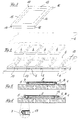
- FIG. 1 shows the carrier plate 1 of the secondary part of a synchronous linear motor with cross bars 2 made of non-magnetic material.
- the cross bars 2 are attached by means of pins 3.
- the pins 3 act as spacer elements for the permanent magnets 4.
- the cross bars 2 are exactly according to the pole pitch of the synchronous linear motor arranged.
- the permanent magnets are between the cross bars 2 4 inserted and glued to the support plate 1.
- To the side Fixing the permanent magnets 4 are lateral positioning pins 5 arranged. After the permanent magnets 4 have been glued, they are joined together of the cover plate 6 consisting of a thin sheet covered, which too has folds 7 and 8 on both sides, which are under spring tension both sides of the permanent magnets 4 can be clamped.
- FIG. 2 corresponds to the embodiment according to FIG. 1, however, are in addition to the side positioning pins Positioning strips 11 and 12 arranged.
- FIG. 3 shows a single frame 13 as a further exemplary embodiment a spacer. 4 are several of these individual frames 13 to a ladder-like holding structure for the permanent magnets 4 summarized. Each individual frame 13 has Centering devices, which on the contact sides 14 and 15 of the Single frame 13 formed wedge-shaped lugs 16 and accordingly there are wedge-shaped bevels 17.
- the Single frame 13 Under the effect of the mutual magnetic attraction the permanent magnet 4 pressed against each other while doing so aligned to a stable straight line by means of the centering devices Holding structure put together.
- the holding structure ensures sticking the permanent magnet 4 for exact adherence to the pole pitch and remains as a lost template on the carrier plate.
- FIG. 5 shows a cross section through a fully assembled secondary part 1 with permanent magnets glued to the carrier plate 1 4 and lateral positioning pins 5. Grips around the cover plate 6 laterally the permanent magnets 4 and is resilient against the Positioning pins 5 pressed folds 7 and 8 attached.
- FIG. 6 shows a cross section through a fully assembled secondary part 4, in which the individual frame 13 from the cover plate 6 are covered.
Description
Die Erfindung betrifft ein Verfahren zur Herstellung eines Synchron-Linearmotors mit einem mit einer Wicklung versehenen Primärteil und einem Sekundärteil, das aus einer langgestreckten, ferromagnetischen Trägerplatte besteht, auf der jeweils einen Parallelspalt zueinander einschließende Permanentmagnete festgeklebt sind.The invention relates to a method for producing a synchronous linear motor with one Winding provided primary part and a secondary part, which consists of a elongated, ferromagnetic carrier plate exists on each a permanent magnet enclosing a parallel gap to one another are.
Bei Synchron-Linearmotoren dieser Art besteht das Problem, daß sich die in alternierender magnetischer Nord-Südpolung anzuordnenden Permanentmagnete während des Klebevorganges infolge der Einwirkung der gegenseitigen magnetischen Kräfte fortbewegen und nicht auf den vorgesehenen Positionen fixieren lassen. Zur Vermeidung dieser Nachteile werden Magnete in der Regel im unmagnetisierten Zustand auf die Trägerplatte aufgebracht und erst nach erfolgter Montage aufmagnetisiert. Eine zur Aufmagnetisierung der befestigten Magnete erforderliche Magnetisiereinrichtung ist jedoch sehr aufwendig.The problem with synchronous linear motors of this type is that the Permanent magnets to be arranged in alternating magnetic north-south polarity during the gluing process due to the influence of the mutual magnetic forces and not on the intended Have positions fixed. To avoid these disadvantages Magnets are usually in the unmagnetized state on the carrier plate applied and magnetized only after assembly. One for Magnetization of the attached magnets required magnetizing device however, is very complex.
Aus der US-3, 828, 121 ist es bekannt, bei einem mit einer tassenförmigen Vertiefung versehenen Schwungrad, am Innenumfang der Vertiefung Permanentmagnete mit Hilfe eines Käfigringes und eines Werkzeugs zur radialen Positionierung der Permanentmagneten festzukleben.From US-3, 828, 121 it is known in one with a cup-shaped recess provided flywheel, with the help of permanent magnets on the inner circumference of the recess a cage ring and a tool for radial positioning of the permanent magnets sticking.
Aus der FR 2 279 246 ist es ferner bekannt, bei einem Läufer einer elektrischen Maschine
die Permanentmagneten in radial nach außen offenen Ausschnitten eines scheibenförmigen
Käfigteils anzuordnen, wobei die Permanentmagneten mittels Nuten in den Randbereichen
der Ausschnitte radial verschiebbar gelagert sind. Sämtliche Permanentmagnete werden von
einem Haltegurt auf ihrer Position in den Ausschnitten gehalten.From
Der Erfindung liegt die Aufgabe zugrunde bei einem Synchron-Linear motor, fertig aufmagnetisierte Permanentmagnete mit geringem Bauaufwand und mit hoher Präzision am Sekundärteil bzw. an der Trägerplatte zu befestigen.The invention has for its object in a synchronous linear motor, fully magnetized Permanent magnets with low construction costs and with high precision on To attach secondary part or to the support plate.
Diese Aufgabe wird nach der Erfindung dadurch gelöst, daß zwischen den Permanentmagneten dem Polteilungsrastermaß des Synchron-Linearmotors entsprechende Distanzelemente aus unmagnetischen Material angeordnet werden.This object is achieved according to the invention in that between the Permanent magnets corresponding to the pitch pattern of the synchronous linear motor Spacers made of non-magnetic material can be arranged.
Die Distanzelemente können aus jeweils zwei in der Trägerplatte nebeneinander angeordneten Distanzstiften bestehen. Da die in einem Sinterungsprozeß hergestellten Permanentmagnete sehr spröde sind, kann es vorteilhaft sein, anstelle der im wesentlichen eine punktuelle Belastung hervorrufenden Distanzstifte Quersprossen anzubringen, an denen die Permanentmagnete in ihre gesamten Breite anliegen. The spacer elements can consist of two in the carrier plate side by side arranged spacers exist. Because the in a sintering process permanent magnets are very brittle, it can be advantageous instead of essentially a point load causing spacer pins to attach crossbars to which the Permanent magnets lie in their entire width.
In gleicher Weise kann die Positionierung der Permanentmagnete an ihren Seiten mittels seitlicher Positionierstifte oder Positionierleisten erfolgen.In the same way, the positioning of the permanent magnets on their Sides using lateral positioning pins or positioning strips respectively.
In einer vorteilhaften Ausführungsform können die Quersprossen und die seitlichen Positionierleisten zu einer einstückigen, leiterartigen Positionierstruktur zusammengefaßt sein.In an advantageous embodiment, the cross bars and the lateral positioning strips to a one-piece, ladder-like Positioning structure can be summarized.
In einer zweckmäßigen Ausgestaltung der Erfindung bestehen die Distanzelemente jeweils aus Einzelrahmen die einen oder mehrere Permanentmagnete umschließen. Vorzugsweise sind diese Einzelrahmen mit Zentriereinrichtungen, beispielsweise mit zentrierenden keilförmigen Vorsprüngen und Ausnehmungen versehen, so daß aufgrund der Ausziehungskraft jeweils zweier benachbarter Permanentmagnete die Einzelrahmen selbstzentrierend zusammengepreßt werden und somit in ihrer Gesamtheit zu einer exakt geraden und stabilen Leiterstruktur zusammengefügt werden. Bei der Herstellung der Einzelrahmen als Kunststoffspritzgießteile ergeben sich billige Bauelemente mit den geeigneten unmagnetischen Eigenschaften.In an expedient embodiment of the invention, the spacer elements exist one or more permanent magnets each from individual frames enclose. These individual frames are preferably with centering devices, for example with centering wedge-shaped projections and recesses, so that due to the pulling force two adjacent permanent magnets self-centering the individual frames be pressed together and thus in their entirety to an exact straight and stable conductor structure. In the Manufacture of the individual frames as plastic injection molded parts result cheap components with the appropriate non-magnetic properties.
Da zum einen die Permanentmagnete aus sehr sprödem und korrosionsanfälligem Material bestehen und zum anderen diese nur zu einem geringen Teil von dem Primärteil überdeckt sind, ist es erforderlich, die offen liegenden Bereiche der Permanentmagnete zu schützen. Hierzu ist es vorteilhaft, die Permanentmagnete mit einem Abdeckblech zu schützen, das an den Seiten mit Falzen versehen ist, die die Permanentmagnete an deren Seitenflächen direkt oder deren seitliche Positionierelemente, wie z.B. die Seitenleisten, die seitlichen Positionierstifte oder die Einzelrahmen umgreifen. Aufgrund der Federungswirkung der Falze ist das Abdeckblech mit dem Sekundärteil verbunden und bildet einen zuverlässigen Schutz gegen mechanische und korrosive Schadeinwirkungen. On the one hand, the permanent magnets made of very brittle and susceptible to corrosion Material exist and on the other hand only a small part are covered by the primary part, it is necessary to open the to protect lying areas of the permanent magnets. This is it advantageous to protect the permanent magnets with a cover plate, the is provided on the sides with folds that the permanent magnets on their Side surfaces directly or their side positioning elements, e.g. the side strips, the side positioning pins or the individual frames embrace. The cover plate is due to the spring effect of the folds connected to the secondary part and forms a reliable Protection against mechanical and corrosive damage.
Die Erfindung wird nachfolgend anhand von in der Zeichnung dargestellten Ausführungsbeispielen erläutert. Es zeigen:
- Fig. 1
- die perspektivische Ansicht der Einzelbauteile eines Sekundärteils,
- Fig. 2
- die Ansicht des Sekundärteils gemäß Fig. 1 mit seitlichen Positionierleisten,
- Fig. 3
- die Darstellung eines Einzelrahmens,
- Fig. 4
- die Darstellung mehrerer auf der Trägerplatte des Sekundärteils befestigter Einzelrahmen,
- Fig. 5
- den Querschnitt durch ein Sekundärteil mit Abdeckblech gemäß Fig. 1 und
- Fig. 6
- den Querschnitt durch ein Sekundärteil gemäß Fig. 4.
- Fig. 1
- the perspective view of the individual components of a secondary part,
- Fig. 2
- the view of the secondary part of FIG. 1 with side positioning strips,
- Fig. 3
- the representation of a single frame,
- Fig. 4
- the representation of several individual frames attached to the support plate of the secondary part,
- Fig. 5
- the cross section through a secondary part with cover plate according to FIG. 1 and
- Fig. 6
- 3 shows the cross section through a secondary part according to FIG. 4.
Die Fig. 1 zeigt die Trägerplatte 1 des Sekundärteils eines Synchron-Linearmotors
mit Quersprossen 2 aus unmagnetischem Material. Die Quersprossen
2 sind mittels Stiften 3 befestigt. Anstelle der Quersprossen 2
können in einer anderen, nicht dargestellten Ausführungsform, die Stifte
3 als Distanzelemente für die Permanentmagnete 4 fungieren. Die Quersprossen
2 sind exakt nach dem Polteilungsrastermaß des Synchron-Linearmotors
angeordnet. Zwischen den Quersprossen 2 werden die Permanentmagnete
4 eingefügt und mit der Trägerplatte 1 verklebt. Zur seitlichen
Fixierung der Permanentmagnete 4 sind seitliche Positionierstifte 5
angeordnet. Nach der Verklebung der Permanentmagnete 4 werden diese mit
der aus einem dünnen Blech bestehenden Abdeckplatte 6 abgedeckt, die zu
beiden Seiten Falze 7 und 8 aufweist, die unter Federvorspannung zu
beiden Seiten der Permanentmagnete 4 festklemmbar sind. 1 shows the carrier plate 1 of the secondary part of a synchronous linear motor
with
Die Ausführungsform nach Fig. 2 entspricht der Ausführungsform nach Fig.
1, jedoch sind zusätzlich neben den seitlichen Positionierstiften
Positionierleisten 11 und 12 angeordnet.The embodiment according to FIG. 2 corresponds to the embodiment according to FIG.
1, however, are in addition to the side positioning
Die Fig. 3 zeigt einen Einzelrahmen 13 als ein weiteres Ausführungsbeispiel
eines Distanzelementes. Gemäß der Darstellung nach Fig. 4 sind
mehrere dieser Einzelrahmen 13 zu einer leiterartigen Haltestruktur für
die Permanentmagnete 4 zusammengefaßt. Jeder Einzelrahmen 13 besitzt
Zentriereinrichtungen, die aus an den Kontaktseiten 14 und 15 der
Einzelrahmen 13 ausgebildeten keilförmigen Nasen 16 und entsprechend
keilförmig gestalteten Abschrägungen 17 bestehen.3 shows a
Bei Belegung der Einzelrahmen 13 mit den Permanentmagneten 4 werden die
Einzelrahmen 13 unter der Wirkung der gegenseitigen magnetischen Anziehungskraft
der Permanentmagnete 4 gegeneinandergedrückt und dabei
mittels der Zentriereinrichtungen fluchtend zu einer stabilen geraden
Haltestruktur zusammengefügt. Die Haltestruktur sorgt beim Festkleben
der Permanentmagnete 4 für eine exakte Einhaltung des Polteilungsrastermaßes
und verbleibt als verlorene Schablone auf der Trägerplatte .When the
Die Fig. 5 zeigt einen Querschnitt durch ein fertig montiertes Sekundärteil
nach Fig. 1 mit auf der Trägerplatte 1 aufgeklebten Permanentmagneten
4 und seitlichen Positionierstiften 5. Die Abdeckplatte 6 umgreift
seitlich die Permanentmagnete 4 und ist mit den federnd gegen die
Positionierstifte 5 gedrückten Falzen 7 und 8 befestigt.5 shows a cross section through a fully assembled secondary part
1 with permanent magnets glued to the carrier plate 1
4 and
Die Fig. 6 zeigt einen Querschnitt durch ein fertig montiertes Sekundärteil
nach Fig. 4, bei dem auch die Einzelrahmen 13 von der Abdeckplatte
6 abgedeckt sind. 6 shows a cross section through a fully assembled
Im fertig montierten Zustand sind die aus sehr sprödem und korrosionsanfälligen
Material bestehenden Permanentmagnete 4 zum einen von den als
verlorene Schablone dienenden Distanzelementen umgeben und zum anderen
von der Abdeckplatte 6 umschlossen, so daß die bruchempfindlichen und
korrosionsanfälligen Permanentmagnete 4 durch eine vollständige Kapselung
geschützt sind. Darüberhinaus wird durch die Distanzelemente
während des Festklebens der Permanentmagnete 4 mit einfachen Mitteln
eine Einhaltung des Polteilungsrastermaßes sichergestellt.When fully assembled, they are made of very brittle and susceptible to corrosion
Material existing
Claims (15)
- Method of producing a synchronous linear motor with a primary part provided with a coil and a secondary part consisting of an elongate ferromagnetic carrier plate on which permanent magnets enclosing a respective parallel slit with one another are stuck, characterised in that spacer elements composed of non-magnetic material and corresponding to the pole pitch grid dimensions of the synchronous linear motor are arranged between the already magnetised permanent magnets (4).
- Method according to claim 1, characterised in that pins (3) are fastened in the carrier plate as spacer elements.
- Method according to claim 2, characterised in that transverse bars (2) which are fixed by means of the pins (3) are arranged as spacer elements.
- Method according to any of claims 1 to 3, characterised in that the permanent magnets (4) are positioned in a lateral direction by locating pins (5) arranged on both sides.
- Method according to any of claims 1 to 4, characterised in that the permanent magnets (4) are positioned in the lateral direction by locating rails (11, 12) arranged on both sides.
- Method according to either of claims 4 or 5, characterised in that the locating rails (11, 12) are fixed on the carrier plate by means of the locating pins (5).
- Method according to claims 3, 5 and 5, characterised in that the transverse bars (2) and the locating rails (11, 12) consist of a single-part locating structure.
- Method according to claim 7, characterised in that the spacer elements consist of single-part individual frames (13) each enclosing one or more permanent magnets (4).
- Method according to claim 8, characterised in that the individual frames (13) have hollowed centring devices which are arranged so as to engage in one another in a centring and aligning manner.
- Method according to claim 9, characterised in that the centring devices consist of wedge-shaped noses (16) which exist on the exterior of the contact sides (14, 15) of each individual frame (13) and engage in correspondingly wedge-shaped bevels (17) of the adjacent individual frames (13).
- Method according to any of claims 8 to 10, characterised in that the individual frames (13) are plastics injection mouldings.
- Method according to claim 10, characterised in that the individual frames (13) are fixed by locating pins (5) arranged on the side of the carrier plate (1).
- Method according to any of claims 1 to 12, characterised in that the permanent magnets (4) are covered by means of a covering plate (6) secured on both sides of the permanent magnets (4).
- Method according to claim 13, characterised in that the covering plate (6) is provided with lateral folds (7, 8) which embrace the permanent magnets (4) and optionally the locating elements at the side.
- Method according to claim 14, characterised in that the folds (7, 8) rest under spring bias on the permanent magnets (4) and optionally on the locating elements.
Applications Claiming Priority (3)
| Application Number | Priority Date | Filing Date | Title |
|---|---|---|---|
| DE19503511A DE19503511C5 (en) | 1995-02-03 | 1995-02-03 | Synchronous linear motor |
| DE19503511 | 1995-02-03 | ||
| PCT/EP1996/000172 WO1996024189A1 (en) | 1995-02-03 | 1996-01-17 | Synchronous linear motor |
Publications (3)
| Publication Number | Publication Date |
|---|---|
| EP0754366A1 EP0754366A1 (en) | 1997-01-22 |
| EP0754366B1 true EP0754366B1 (en) | 2002-06-19 |
| EP0754366B2 EP0754366B2 (en) | 2008-08-20 |
Family
ID=7753087
Family Applications (1)
| Application Number | Title | Priority Date | Filing Date |
|---|---|---|---|
| EP96900964A Expired - Lifetime EP0754366B2 (en) | 1995-02-03 | 1996-01-17 | Method of manufacturing a synchronous linear motor |
Country Status (6)
| Country | Link |
|---|---|
| US (1) | US5952742A (en) |
| EP (1) | EP0754366B2 (en) |
| JP (1) | JPH09511380A (en) |
| KR (1) | KR970702609A (en) |
| DE (3) | DE19503511C5 (en) |
| WO (1) | WO1996024189A1 (en) |
Cited By (4)
| Publication number | Priority date | Publication date | Assignee | Title |
|---|---|---|---|---|
| CN103326535A (en) * | 2012-03-19 | 2013-09-25 | 发那科株式会社 | Magnet plate for linear motor for preventing misalignment of magnets |
| US9771000B2 (en) | 2009-01-23 | 2017-09-26 | Magnemotion, Inc. | Short block linear synchronous motors and switching mechanisms |
| US9802507B2 (en) | 2013-09-21 | 2017-10-31 | Magnemotion, Inc. | Linear motor transport for packaging and other uses |
| US10112777B2 (en) | 2009-01-23 | 2018-10-30 | Magnemotion, Inc. | Transport system powered by short block linear synchronous motors |
Families Citing this family (50)
| Publication number | Priority date | Publication date | Assignee | Title |
|---|---|---|---|---|
| DE19643518A1 (en) * | 1996-07-08 | 1998-01-22 | Pasim Mikrosystemtechnik Gmbh | Linear drive with active unit and passive unit also guide and control units e.g. for precision engineering |
| DE19838132B4 (en) * | 1998-08-21 | 2008-04-10 | Siemens Ag | Synchronous linear motor |
| DE19853250B4 (en) * | 1998-11-18 | 2012-02-02 | Siemens Ag | Secondary part for a linear motor |
| DE19936064B4 (en) * | 1999-07-30 | 2011-07-07 | Siemens AG, 80333 | Secondary part for a linear motor and linear motor and method for producing a secondary part |
| US6365993B1 (en) * | 2000-04-07 | 2002-04-02 | Eaton Corporation | Round linear actuator utilizing flat permanent magnets |
| MY133384A (en) | 2000-07-17 | 2007-11-30 | Inventio Ag | Secondary part of a linear motor, method for the production thereof, linear motor with secondary part and use of the linear motor |
| CH695153A5 (en) * | 2000-08-31 | 2005-12-30 | Etel Sa | Assembly of a linear motor and method for mounting this unit. |
| EP1516407B1 (en) * | 2002-05-24 | 2006-08-23 | Velocity Magnetics, Inc. | Primary member of a linear synchronous permanent magnet motor |
| US6936937B2 (en) * | 2002-06-14 | 2005-08-30 | Sunyen Co., Ltd. | Linear electric generator having an improved magnet and coil structure, and method of manufacture |
| AU2003281676A1 (en) | 2002-07-26 | 2004-02-16 | Crisplant A/S | A conveyor and a method of providing a driving force to a conveyor |
| US20060011093A1 (en) * | 2002-07-26 | 2006-01-19 | Viggo Jensen | Conveyor and a method of providing a driving force to a conveyor |
| US6943508B2 (en) | 2002-09-23 | 2005-09-13 | Otis Elevator Company | Tubular linear synchronous motor control for elevator doors |
| JP4521221B2 (en) * | 2004-05-18 | 2010-08-11 | 日本トムソン株式会社 | Slide device with built-in movable magnet type linear motor |
| US8727078B2 (en) | 2004-05-28 | 2014-05-20 | Velocity Magnetics, Inc. | Selectively incrementally actuated linear eddy current braking system |
| JP2006174583A (en) * | 2004-12-15 | 2006-06-29 | Fanuc Ltd | Linear motor |
| WO2007116505A1 (en) * | 2006-03-31 | 2007-10-18 | Hitachi, Ltd. | Linear motor |
| CN101371428A (en) * | 2006-03-31 | 2009-02-18 | 株式会社日立制作所 | Linear motor |
| DE102006022191A1 (en) * | 2006-05-12 | 2007-11-15 | Rovema - Verpackungsmaschinen Gmbh | Bag machine for packaging purposes |
| FR2903823B1 (en) * | 2006-07-12 | 2008-09-05 | Messier Dowty Sa | ELECTROMAGNETIC MACHINE ACTIVE ELEMENT, METHOD OF MANUFACTURING SUCH ACTIVE ELEMENT, AND ELECTROMAGNETIC MACHINE COMPRISING SUCH ACTIVE ELEMENT. |
| DE102006048966A1 (en) * | 2006-10-17 | 2008-04-30 | Siemens Ag | Magnet module for a permanent magnet excited electric machine |
| WO2008134796A1 (en) | 2007-05-03 | 2008-11-13 | In Motion Technologies Pty Ltd | Rotor magnet positioning device |
| US8967051B2 (en) | 2009-01-23 | 2015-03-03 | Magnemotion, Inc. | Transport system powered by short block linear synchronous motors and switching mechanism |
| ES2387433B1 (en) * | 2009-05-28 | 2013-08-08 | Gamesa Innovation & Technology, S.L. | METHOD OF MAGNET ASSEMBLY IN GENERATORS AND ENGINES OF WIND TURBINES AND CONSEQUENTIALLY MAGNET ASSEMBLY. |
| CN102549885A (en) | 2009-09-29 | 2012-07-04 | 西门子公司 | Rotor |
| DE102010041585A1 (en) | 2010-09-29 | 2012-03-29 | Siemens Aktiengesellschaft | Rotor for use as inner rotor of e.g. linear electric machine for permanent synchronous generator of wind power station, has permanent magnets mounted on periphery of rotor body where each pocket is intractable and connected with rotor body |
| JP5536151B2 (en) | 2011-08-25 | 2014-07-02 | ファナック株式会社 | Manufacturing method of magnet plate for linear motor |
| EP2574821B1 (en) | 2011-09-30 | 2013-10-30 | Siemens Aktiengesellschaft | Active oscillation attenuator without direct acceleration detection |
| DE102012025324A1 (en) * | 2012-12-22 | 2014-06-26 | Festo Ag & Co. Kg | Linear direct drive stator for electro-dynamic propulsion system, has magnetic coils whose major axis is set transverse to long edge of support plate along movement axis of support surface of support plate |
| CN104981969B (en) * | 2013-02-20 | 2016-12-07 | 三菱电机株式会社 | Movable piece and possess the linear motor of this movable piece |
| EP2955824B1 (en) | 2014-06-11 | 2017-05-31 | Etel S. A.. | Secondary part of a synchronous motor with a protective device for magnets |
| EP3032724B1 (en) | 2014-12-11 | 2020-05-13 | Siemens Aktiengesellschaft | Secondary part with template |
| US9859763B2 (en) | 2015-10-02 | 2018-01-02 | E-Circuit Motors, Inc. | Structures and methods for controlling losses in printed circuit boards |
| US11527933B2 (en) | 2015-10-02 | 2022-12-13 | E-Circuit Motors, Inc. | Stator and rotor design for periodic torque requirements |
| US10170953B2 (en) | 2015-10-02 | 2019-01-01 | E-Circuit Motors, Inc. | Planar composite structures and assemblies for axial flux motors and generators |
| US9800109B2 (en) | 2015-10-02 | 2017-10-24 | E-Circuit Motors, Inc. | Structures and methods for controlling losses in printed circuit boards |
| US11121614B2 (en) | 2017-06-05 | 2021-09-14 | E-Circuit Motors, Inc. | Pre-warped rotors for control of magnet-stator gap in axial flux machines |
| US9673688B2 (en) | 2015-10-02 | 2017-06-06 | E-Circuit Motors, Inc. | Apparatus and method for forming a magnet assembly |
| US9673684B2 (en) | 2015-10-02 | 2017-06-06 | E-Circuit Motors, Inc. | Structures and methods for thermal management in printed circuit board stators |
| EP3232550A1 (en) * | 2016-04-12 | 2017-10-18 | Robert Bosch Gmbh | Secondary part of a linear motor |
| US10476364B2 (en) * | 2016-06-15 | 2019-11-12 | Asm Technology Singapore Pte Ltd | Magnet assembly mounting arrangement for an electromagnetic motor |
| US10686355B2 (en) | 2016-07-15 | 2020-06-16 | Magnemotion, Inc. | Transport system puck assembly |
| US11005322B2 (en) | 2017-06-05 | 2021-05-11 | E-Circuit Motors, Inc. | Rotor assemblies for axial flux machines |
| US11831211B2 (en) | 2017-06-05 | 2023-11-28 | E-Circuit Motors, Inc. | Stator and rotor design for periodic torque requirements |
| EP3661033A1 (en) * | 2018-11-27 | 2020-06-03 | B&R Industrial Automation GmbH | Transport device in the form of a linear motor with guideway stator |
| EP3719962A1 (en) | 2019-04-01 | 2020-10-07 | LIM-Tech Limited | Electromotive machine |
| DE202020106227U1 (en) * | 2020-10-30 | 2022-02-01 | Schunk Electronic Solutions Gmbh | Secondary part for a linear motor, linear motor and modular system for a linear motor with magnet bodies and replacement bodies |
| CA3209142A1 (en) | 2021-02-17 | 2022-08-25 | E-Circuit Motors, Inc. | Planar stator configurations for axial flux machines |
| AU2022318884A1 (en) | 2021-07-30 | 2024-01-25 | E-Circuit Motors, Inc. | Magnetic material filled printed circuit boards and printed circuit board stators |
| US11336130B1 (en) | 2021-08-17 | 2022-05-17 | E-Circuit Motors, Inc. | Low-loss planar winding configurations for an axial flux machine |
| WO2024013987A1 (en) * | 2022-07-15 | 2024-01-18 | ファナック株式会社 | Linear motor magnet plate |
Family Cites Families (19)
| Publication number | Priority date | Publication date | Assignee | Title |
|---|---|---|---|---|
| US2463936A (en) * | 1946-03-21 | 1949-03-08 | Chance Brothers Ltd | Dynamoelectric machine |
| US3518593A (en) * | 1968-02-26 | 1970-06-30 | Ibm | Magnetic handling device |
| US3828212A (en) * | 1971-09-16 | 1974-08-06 | Briggs & Stratton Corp | Assembly of alternator magnet blocks with engine flywheel |
| FR2279246A1 (en) * | 1974-07-19 | 1976-02-13 | Cem Comp Electro Mec | Inductor for permanent magnet axial air gap machine - with slotted insulation plate for defining magnet location |
| DE2742050A1 (en) * | 1977-09-19 | 1979-03-29 | Papst Motoren Kg | MULTI-PHASE LINEAR MOTOR |
| DE2933450A1 (en) * | 1979-08-17 | 1981-02-26 | Heidelberg Goetz | SYNCHRONOUS LINEAR MOTOR, IN PARTICULAR FOR DRIVING MAGNETIC FLOATING VEHICLES |
| US4587450A (en) * | 1984-01-06 | 1986-05-06 | Sanyei Corporation | Synchronous motor rotor |
| JPS63217965A (en) * | 1987-03-05 | 1988-09-12 | Shinko Electric Co Ltd | Linear motor |
| US4803387A (en) * | 1987-06-29 | 1989-02-07 | Fmc Corporation | Electric drive motor |
| US5051225A (en) * | 1988-06-22 | 1991-09-24 | E. I. Du Pont De Nemours And Company | Method of drawing plastic film in a tenter frame |
| US4859974A (en) * | 1988-10-11 | 1989-08-22 | General Electric Company | Electromagnetic motor/actuator |
| DE3923974A1 (en) * | 1989-07-20 | 1991-01-31 | Swf Auto Electric Gmbh | METHOD FOR PRODUCING AN ELECTRIC MOTOR |
| JPH0549299A (en) * | 1991-06-28 | 1993-02-26 | Sony Corp | Multimode step motor |
| EP0594757B1 (en) * | 1991-07-12 | 1998-06-17 | Denne Developments Limited | Electromagnetic apparatus for producing linear motion |
| JP3000091B2 (en) * | 1991-09-09 | 2000-01-17 | 東日本旅客鉄道株式会社 | Cart for linear motor vehicle upper field |
| FR2691592A1 (en) * | 1992-01-09 | 1993-11-26 | Levy Daniel | Variable magnetic field segment sheet device for supporting sintered magnets - has flexible non-ferromagnetic thin sheet, folded to create open compartments for set of flat magnets with like poles facing open side. |
| JPH05211760A (en) * | 1992-01-30 | 1993-08-20 | Hitachi Metals Ltd | Magnetic circuit |
| DE4302807C2 (en) * | 1993-02-02 | 1995-03-23 | Wolfgang Hill | Multi-phase electrical machine and process for its manufacture |
| DE4337934A1 (en) * | 1993-11-06 | 1995-05-18 | Magnetbahn Gmbh | Attachment of permanent magnets to magnetic carriers and method for their execution |
-
1995
- 1995-02-03 DE DE19503511A patent/DE19503511C5/en not_active Expired - Lifetime
- 1995-02-03 DE DE29520879U patent/DE29520879U1/en not_active Expired - Lifetime
-
1996
- 1996-01-17 DE DE59609360T patent/DE59609360D1/en not_active Expired - Lifetime
- 1996-01-17 WO PCT/EP1996/000172 patent/WO1996024189A1/en active IP Right Grant
- 1996-01-17 EP EP96900964A patent/EP0754366B2/en not_active Expired - Lifetime
- 1996-01-17 JP JP8523201A patent/JPH09511380A/en active Pending
- 1996-01-17 US US08/722,028 patent/US5952742A/en not_active Expired - Lifetime
- 1996-01-17 KR KR1019960705489A patent/KR970702609A/en not_active Application Discontinuation
Cited By (4)
| Publication number | Priority date | Publication date | Assignee | Title |
|---|---|---|---|---|
| US9771000B2 (en) | 2009-01-23 | 2017-09-26 | Magnemotion, Inc. | Short block linear synchronous motors and switching mechanisms |
| US10112777B2 (en) | 2009-01-23 | 2018-10-30 | Magnemotion, Inc. | Transport system powered by short block linear synchronous motors |
| CN103326535A (en) * | 2012-03-19 | 2013-09-25 | 发那科株式会社 | Magnet plate for linear motor for preventing misalignment of magnets |
| US9802507B2 (en) | 2013-09-21 | 2017-10-31 | Magnemotion, Inc. | Linear motor transport for packaging and other uses |
Also Published As
| Publication number | Publication date |
|---|---|
| EP0754366B2 (en) | 2008-08-20 |
| DE29520879U1 (en) | 1996-04-11 |
| US5952742A (en) | 1999-09-14 |
| DE19503511A1 (en) | 1996-08-08 |
| DE59609360D1 (en) | 2002-07-25 |
| EP0754366A1 (en) | 1997-01-22 |
| DE19503511C5 (en) | 2010-11-04 |
| JPH09511380A (en) | 1997-11-11 |
| KR970702609A (en) | 1997-05-13 |
| WO1996024189A1 (en) | 1996-08-08 |
| DE19503511C2 (en) | 2000-12-28 |
Similar Documents
| Publication | Publication Date | Title |
|---|---|---|
| EP0754366B1 (en) | Method of manufacturing a synchronous linear motor | |
| DE2742050C2 (en) | ||
| EP0559665B1 (en) | Stator for an electric motor | |
| DE102010064051A1 (en) | Winding carrier for the isolation of a single-tooth winding in electrical machines | |
| DE3890737C2 (en) | ||
| DE3341625C2 (en) | ||
| DE102004017157A1 (en) | Method for producing a rotor assembly and rotor assembly for an electrical machine | |
| DE102005045348A1 (en) | Tooth module for a permanent magnet excited primary part of an electrical machine | |
| DE3125694A1 (en) | COLLECTORLESS DC MOTOR | |
| EP3032724B1 (en) | Secondary part with template | |
| EP0307706B1 (en) | Array of permanent magnets | |
| DE19622186A1 (en) | Electric motor | |
| DE19953650C2 (en) | Process for the production and storage of individual magnetic components and their assembly for the production of miniaturized magnet systems and such magnet systems | |
| DE4420371A1 (en) | Electric motor, in particular for a hard disk drive, with a stator and a rotor | |
| WO2018219390A1 (en) | Cost-optimised rotor of an electrical machine | |
| WO1995020258A1 (en) | Cage for securing permanent magnets in a stator of an electric motor | |
| DE3002899C2 (en) | Pickup system with moving coil | |
| DE2603680C3 (en) | Linear motors, in particular for indicating and writing measuring devices | |
| DE10247907A1 (en) | Rotor for electrical machine e.g. synchronous machine, has corresponding guide elements at permanent magnets and carrier engaging into each other for secure hold | |
| EP0226891B1 (en) | Method of manufacturing an electromagnetic relay without adjusting | |
| EP3457529B1 (en) | Disc motor | |
| DE3244326C1 (en) | Holder for pole coils, surrounding salient poles which have no pole shoes and are of rectangular cross-section, of an electrical machine | |
| EP3203609A1 (en) | Rotor for a permanently magnetically excited synchronous machine, pole gap rod such a rotor and method for producing such a rotor | |
| DE2503227A1 (en) | Yoke for electric motor permanent magnets - has windows for magnets and outer flux return sheath holding magnets in place | |
| DE1965326C3 (en) | Plane collector combination for small electric motors |
Legal Events
| Date | Code | Title | Description |
|---|---|---|---|
| PUAI | Public reference made under article 153(3) epc to a published international application that has entered the european phase |
Free format text: ORIGINAL CODE: 0009012 |
|
| AK | Designated contracting states |
Kind code of ref document: A1 Designated state(s): CH DE FR GB IT LI |
|
| 17P | Request for examination filed |
Effective date: 19970210 |
|
| RIN1 | Information on inventor provided before grant (corrected) |
Inventor name: ROSNER, PETER Inventor name: STOIBER, DIETMAR |
|
| RAP1 | Party data changed (applicant data changed or rights of an application transferred) |
Owner name: INTRASYS GMBH DR.ROSNER & PARTNER Owner name: KRAUSS-MAFFEI AKTIENGESELLSCHAFT |
|
| 17Q | First examination report despatched |
Effective date: 19981130 |
|
| RAP1 | Party data changed (applicant data changed or rights of an application transferred) |
Owner name: INTRASYS GMBH DR.ROSNER & PARTNER Owner name: SIEMENS LINEAR MOTOR SYSTEMS GMBH & CO. KG |
|
| RBV | Designated contracting states (corrected) |
Designated state(s): CH DE FR GB IT LI |
|
| RTI1 | Title (correction) |
Free format text: METHOD OF MANUFACTURING A SYNCHRONOUS LINEAR MOTOR |
|
| GRAG | Despatch of communication of intention to grant |
Free format text: ORIGINAL CODE: EPIDOS AGRA |
|
| GRAG | Despatch of communication of intention to grant |
Free format text: ORIGINAL CODE: EPIDOS AGRA |
|
| GRAH | Despatch of communication of intention to grant a patent |
Free format text: ORIGINAL CODE: EPIDOS IGRA |
|
| RAP1 | Party data changed (applicant data changed or rights of an application transferred) |
Owner name: INTRASYS GMBH INNOVATIVE TRANSPORT-SYSTEME |
|
| GRAH | Despatch of communication of intention to grant a patent |
Free format text: ORIGINAL CODE: EPIDOS IGRA |
|
| GRAA | (expected) grant |
Free format text: ORIGINAL CODE: 0009210 |
|
| AK | Designated contracting states |
Kind code of ref document: B1 Designated state(s): CH DE FR GB IT LI |
|
| REG | Reference to a national code |
Ref country code: GB Ref legal event code: FG4D Free format text: NOT ENGLISH |
|
| REG | Reference to a national code |
Ref country code: CH Ref legal event code: EP |
|
| GBT | Gb: translation of ep patent filed (gb section 77(6)(a)/1977) |
Effective date: 20020619 |
|
| REG | Reference to a national code |
Ref country code: CH Ref legal event code: NV Representative=s name: A. BRAUN, BRAUN, HERITIER, ESCHMANN AG PATENTANWAE |
|
| REF | Corresponds to: |
Ref document number: 59609360 Country of ref document: DE Date of ref document: 20020725 |
|
| PGFP | Annual fee paid to national office [announced via postgrant information from national office to epo] |
Ref country code: FR Payment date: 20021114 Year of fee payment: 8 |
|
| ET | Fr: translation filed | ||
| PLBI | Opposition filed |
Free format text: ORIGINAL CODE: 0009260 |
|
| PLBQ | Unpublished change to opponent data |
Free format text: ORIGINAL CODE: EPIDOS OPPO |
|
| 26 | Opposition filed |
Opponent name: SEW-EURODRIVE GMBH & CO Effective date: 20030218 |
|
| PLBF | Reply of patent proprietor to notice(s) of opposition |
Free format text: ORIGINAL CODE: EPIDOS OBSO |
|
| PLAX | Notice of opposition and request to file observation + time limit sent |
Free format text: ORIGINAL CODE: EPIDOSNOBS2 |
|
| PLBB | Reply of patent proprietor to notice(s) of opposition received |
Free format text: ORIGINAL CODE: EPIDOSNOBS3 |
|
| PGFP | Annual fee paid to national office [announced via postgrant information from national office to epo] |
Ref country code: GB Payment date: 20040116 Year of fee payment: 9 |
|
| PG25 | Lapsed in a contracting state [announced via postgrant information from national office to epo] |
Ref country code: FR Free format text: LAPSE BECAUSE OF NON-PAYMENT OF DUE FEES Effective date: 20040930 |
|
| REG | Reference to a national code |
Ref country code: FR Ref legal event code: ST |
|
| PG25 | Lapsed in a contracting state [announced via postgrant information from national office to epo] |
Ref country code: IT Free format text: LAPSE BECAUSE OF NON-PAYMENT OF DUE FEES;WARNING: LAPSES OF ITALIAN PATENTS WITH EFFECTIVE DATE BEFORE 2007 MAY HAVE OCCURRED AT ANY TIME BEFORE 2007. THE CORRECT EFFECTIVE DATE MAY BE DIFFERENT FROM THE ONE RECORDED. Effective date: 20050117 Ref country code: GB Free format text: LAPSE BECAUSE OF NON-PAYMENT OF DUE FEES Effective date: 20050117 |
|
| APBP | Date of receipt of notice of appeal recorded |
Free format text: ORIGINAL CODE: EPIDOSNNOA2O |
|
| APAH | Appeal reference modified |
Free format text: ORIGINAL CODE: EPIDOSCREFNO |
|
| GBPC | Gb: european patent ceased through non-payment of renewal fee |
Effective date: 20050117 |
|
| APAH | Appeal reference modified |
Free format text: ORIGINAL CODE: EPIDOSCREFNO |
|
| APBQ | Date of receipt of statement of grounds of appeal recorded |
Free format text: ORIGINAL CODE: EPIDOSNNOA3O |
|
| RAP2 | Party data changed (patent owner data changed or rights of a patent transferred) |
Owner name: SIEMENS AG |
|
| RAP2 | Party data changed (patent owner data changed or rights of a patent transferred) |
Owner name: SIEMENS AKTIENGESELLSCHAFT |
|
| REG | Reference to a national code |
Ref country code: CH Ref legal event code: PUE Owner name: SIEMENS AKTIENGESELLSCHAFT Free format text: INTRASYS GMBH INNOVATIVE TRANSPORT-SYSTEME#GOLLIERSTRASSE 70#80339 MUENCHEN (DE) -TRANSFER TO- SIEMENS AKTIENGESELLSCHAFT#WITTELSBACHERPLATZ 2#80333 MUENCHEN (DE) |
|
| APBU | Appeal procedure closed |
Free format text: ORIGINAL CODE: EPIDOSNNOA9O |
|
| REG | Reference to a national code |
Ref country code: CH Ref legal event code: PFA Owner name: SIEMENS AKTIENGESELLSCHAFT Free format text: SIEMENS AKTIENGESELLSCHAFT#WITTELSBACHERPLATZ 2#80333 MUENCHEN (DE) -TRANSFER TO- SIEMENS AKTIENGESELLSCHAFT#WITTELSBACHERPLATZ 2#80333 MUENCHEN (DE) |
|
| PUAH | Patent maintained in amended form |
Free format text: ORIGINAL CODE: 0009272 |
|
| STAA | Information on the status of an ep patent application or granted ep patent |
Free format text: STATUS: PATENT MAINTAINED AS AMENDED |
|
| 27A | Patent maintained in amended form |
Effective date: 20080820 |
|
| AK | Designated contracting states |
Kind code of ref document: B2 Designated state(s): CH DE FR GB IT LI |
|
| REG | Reference to a national code |
Ref country code: CH Ref legal event code: AEN Free format text: AUFRECHTERHALTUNG DES PATENTES IN GEAENDERTER FORM |
|
| PLAB | Opposition data, opponent's data or that of the opponent's representative modified |
Free format text: ORIGINAL CODE: 0009299OPPO |
|
| PGFP | Annual fee paid to national office [announced via postgrant information from national office to epo] |
Ref country code: IT Payment date: 20070626 Year of fee payment: 12 |
|
| PGRI | Patent reinstated in contracting state [announced from national office to epo] |
Ref country code: IT Effective date: 20091201 |
|
| REG | Reference to a national code |
Ref country code: DE Ref legal event code: R084 Ref document number: 59609360 Country of ref document: DE Effective date: 20130627 |
|
| PGRI | Patent reinstated in contracting state [announced from national office to epo] |
Ref country code: IT Effective date: 20091201 |
|
| PGFP | Annual fee paid to national office [announced via postgrant information from national office to epo] |
Ref country code: DE Payment date: 20140320 Year of fee payment: 19 |
|
| REG | Reference to a national code |
Ref country code: CH Ref legal event code: PCAR Free format text: NEW ADDRESS: HOLBEINSTRASSE 36-38, 4051 BASEL (CH) |
|
| PGFP | Annual fee paid to national office [announced via postgrant information from national office to epo] |
Ref country code: CH Payment date: 20140407 Year of fee payment: 19 |
|
| REG | Reference to a national code |
Ref country code: DE Ref legal event code: R119 Ref document number: 59609360 Country of ref document: DE |
|
| REG | Reference to a national code |
Ref country code: CH Ref legal event code: PL |
|
| PG25 | Lapsed in a contracting state [announced via postgrant information from national office to epo] |
Ref country code: LI Free format text: LAPSE BECAUSE OF NON-PAYMENT OF DUE FEES Effective date: 20150131 Ref country code: CH Free format text: LAPSE BECAUSE OF NON-PAYMENT OF DUE FEES Effective date: 20150131 Ref country code: DE Free format text: LAPSE BECAUSE OF NON-PAYMENT OF DUE FEES Effective date: 20150801 |