EP1516407B1 - Primary member of a linear synchronous permanent magnet motor - Google Patents
Primary member of a linear synchronous permanent magnet motor Download PDFInfo
- Publication number
- EP1516407B1 EP1516407B1 EP03755491A EP03755491A EP1516407B1 EP 1516407 B1 EP1516407 B1 EP 1516407B1 EP 03755491 A EP03755491 A EP 03755491A EP 03755491 A EP03755491 A EP 03755491A EP 1516407 B1 EP1516407 B1 EP 1516407B1
- Authority
- EP
- European Patent Office
- Prior art keywords
- back plate
- frame
- magnets
- synchronous
- permanent magnet
- Prior art date
- Legal status (The legal status is an assumption and is not a legal conclusion. Google has not performed a legal analysis and makes no representation as to the accuracy of the status listed.)
- Expired - Lifetime
Links
Images


Classifications
-
- H—ELECTRICITY
- H02—GENERATION; CONVERSION OR DISTRIBUTION OF ELECTRIC POWER
- H02K—DYNAMO-ELECTRIC MACHINES
- H02K41/00—Propulsion systems in which a rigid body is moved along a path due to dynamo-electric interaction between the body and a magnetic field travelling along the path
- H02K41/02—Linear motors; Sectional motors
- H02K41/03—Synchronous motors; Motors moving step by step; Reluctance motors
- H02K41/031—Synchronous motors; Motors moving step by step; Reluctance motors of the permanent magnet type
-
- H—ELECTRICITY
- H01—ELECTRIC ELEMENTS
- H01L—SEMICONDUCTOR DEVICES NOT COVERED BY CLASS H10
- H01L2924/00—Indexing scheme for arrangements or methods for connecting or disconnecting semiconductor or solid-state bodies as covered by H01L24/00
- H01L2924/0001—Technical content checked by a classifier
- H01L2924/0002—Not covered by any one of groups H01L24/00, H01L24/00 and H01L2224/00
-
- H—ELECTRICITY
- H02—GENERATION; CONVERSION OR DISTRIBUTION OF ELECTRIC POWER
- H02K—DYNAMO-ELECTRIC MACHINES
- H02K1/00—Details of the magnetic circuit
- H02K1/06—Details of the magnetic circuit characterised by the shape, form or construction
- H02K1/22—Rotating parts of the magnetic circuit
- H02K1/27—Rotor cores with permanent magnets
- H02K1/2706—Inner rotors
- H02K1/272—Inner rotors the magnetisation axis of the magnets being perpendicular to the rotor axis
- H02K1/274—Inner rotors the magnetisation axis of the magnets being perpendicular to the rotor axis the rotor consisting of two or more circumferentially positioned magnets
- H02K1/2753—Inner rotors the magnetisation axis of the magnets being perpendicular to the rotor axis the rotor consisting of two or more circumferentially positioned magnets the rotor consisting of magnets or groups of magnets arranged with alternating polarity
- H02K1/276—Magnets embedded in the magnetic core, e.g. interior permanent magnets [IPM]
-
- H—ELECTRICITY
- H02—GENERATION; CONVERSION OR DISTRIBUTION OF ELECTRIC POWER
- H02K—DYNAMO-ELECTRIC MACHINES
- H02K2201/00—Specific aspects not provided for in the other groups of this subclass relating to the magnetic circuits
- H02K2201/06—Magnetic cores, or permanent magnets characterised by their skew
Definitions
- the invention relates to synchronous motors, and in particular to linear synchronous motors with multiple time constant circuits and an improved method of mounting permanent magnets.
- An embodiment provides an electrically synchronous linear secondary stator member that accompanies a primary member, the synchronous linear permanent magnet motor.
- An embodiment is utilized as an electro-dynamic brake for elevators as well as amusement rides such as drop towers, roller coasters and any other mobile device that requires dependable and high thrust braking applications.
- Figure 8 shows narrow slots cut out at a 5-10 degree angle, the pole pitch spacing, the discrete synchronous current loop, the non-conductive barrier around the inside edge of the slot, the highly permeable steel or ferrite core within the slot and two one-piece dissimilar conductive layers, shown as (t1) aluminum and (t2) copper.
- Figure 9 illustrates the vertical X & Y axis view of the synchronous linear secondary stator member. The illustration shows narrow slots cut out at a 90 degree angle, the pole pitch spacing, the discrete synchronous current loop, the non-conductive insulation barrier around the inside edge of the slot, the highly permeable steel or ferrite core within the slot and two one-piece dissimilar conductive layers, shown as (t1) copper and (t2) aluminum.
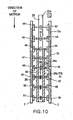
- the primary member in an embodiment consists of a double sided linear synchronous motor consisting of at least two permanent magnets of negative and positive polarity situated on opposite sides of the secondary stator member (transverse axis) as illustrated in figure 10, for example.
- Magnets 44, 34, 35, 36 as illustrated in figure 10 are arranged so as to face positive and magnets 45, 37, 38, 39 are arranged so as to face negative. Wherein this arrangement allows a flux return circuit 26 to occur through the secondary stator member 25.
- figure 10 illustrates an eight pole permanent magnet configuration 1.
- Tp is the pole pitch of the linear synchronous permanent magnet member in meters and Vs is the entry velocity of the vehicle.
- f is the frequency produced in Hertz.
- the invention can also be configured to where the secondary synchronous conductive disc, 2 would be attached in a stationary manner to prevent rotation.
- the primary synchronous permanent magnet motor would be attached to and rotate with the rotating member.
- the rotating primary synchronous permanent magnet motor would continue to be designed to slide or actuate in a variable manner transversely or perpendicular to the fixed synchronous secondary disc, 2 as illustrated in figure 3.
Abstract
Description
- The invention relates to synchronous motors, and in particular to linear synchronous motors with multiple time constant circuits and an improved method of mounting permanent magnets. An embodiment provides an electrically synchronous linear secondary stator member that accompanies a primary member, the synchronous linear permanent magnet motor. An embodiment is utilized as an electro-dynamic brake for elevators as well as amusement rides such as drop towers, roller coasters and any other mobile device that requires dependable and high thrust braking applications.
- This invention reduces or eliminates specialized tooling to attach, guide and secure into place several permanent magnets with alternating poles, situated side by side by incorporating these features into a ferromagnetic back plate and one-piece double laminated frame and cover system. In doing so, the invention eliminates the need for use of raised individual spacers, individual frame pieces and guide pins which have been utilized in previous art.
- The invention improves upon existing methods of permanent magnet electro-dynamic braking. In an embodiment the system is completely synchronous. It does not operate as an eddy current induction type electrical device. The synchronous system operates differently than existing eddy current induction type brakes by directing the electrical currents into discrete circuit pathways thereby routing currents in a particular pathway along the synchronous stator. The stator electrical frequency of this system can be customized, meaning increased or decreased, for any given application, thereby allowing a variable braking force throughout the entire active braking area. This is not possible with existing solid induction type, linear stator rails made from conductive material. This allows for a wide variety of braking applications.
- US-A-5.952.742 discloses a primary member of a liners synchronous permanent magnet motor comprising:
- (a) a ferromagnetic back plate
- (b) an array of permanent magnets, the permanent magnets arranged in alternating polarity, and
- (c) a frame made of a conductive alloy mated to said ferromagnetic back plate, said frame arranged to maintain the desired pole pitch spacing between each magnet.
- WO-A-0207291 discloses a primary member of a liners synchronous permanent magnet motor comprising:
- (b) an array of permanent magnets, the permanent magnets arranged in alternating polarity, and
- (c) a frame showing ladder-type segments to maintain the desired pole pitch spacing between each magnet.
- EP-A-0.359.549 discloses a primary member of a liners synchronous permanent magnet motor comprising:
- (a) a ferromagnetic back plate, the ferromagnetic back plate further comprising bumps (3) machined therein to accept a permanent magnet array, said bumps spaced apart at a predetermined pole pitch spacing
- (b) an array of permanent magnets, the permanent magnets arranged in alternating polarity, said magnets accepted by said bumps, said bumps surrounding the magnets and keeping the magnets in place.
- The invention is defined by the features of
independent claim 1. Preferred embodiments of the invention are defined in the dependent claims. -
- Figure 1 is a latitude cross section view of the assembly showing the ferromagnetic back plate with the machined countersunk magnet slots, the non-ferromagnetic conductive type frame with the o'ring seal groove, the conductive type material frame, the encapsulating case that welds to the frames, the magnet and the flat head countersunk non-magnetic bolts.
- Figure 2 is a longitudinal cross section view of the assembly, illustrating the magnet pole arrangement, the flux path circuit, the machined countersunk magnet slots and the perspective frames.
- Figure 3 illustrates a cutaway of the ferromagnetic back plate, the magnet, the bolt pattern, the non-ferromagnetic conductive frame and o'ring seal groove, the conductive frame and the encapsulating case that welds to the frames.
- Figure 4 illustrates the ferromagnetic back plate and the bolt pattern.
- Figure 5 illustrates a top view of the ferromagnetic back plate and the countersunk magnet retaining slots.
- Figure 6 illustrates the ferromagnetic back plate and frame and case as an assembly.
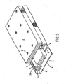
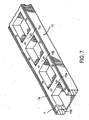
- Figure 7 is a three dimensional cutaway drawing showing the cast or extruded, machined one piece conductive type alloy frame/cover and the o'ring seal groove.
- Figure 8 illustrates the vertical X & Y axis view of the synchronous linear secondary stator member with narrow slots cut out at a 5-10 degree angle.
- Figure 9 illustrates the vertical X & Y axis view of the synchronous linear secondary stator member with narrow slots cut out at a 90 degree angle.
- Figure 10 illustrates a cutaway vertical X & Y axis view of the preferred embodiment of the braking system, which includes the primary synchronous linear permanent magnet motor and the synchronous linear secondary stator member.
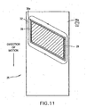
- Figure 11 illustrates an enlarged vertical X & Y axis view of the one-piece synchronous linear secondary stator member having one enlarged narrow slot with a non-conductive insulating barrier around the inside edge of the slot, the highly permeable steel or ferrite core within the slot and the discrete synchronous current loop.
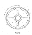
- Figure 13 top view illustration of the primary synchronous rotary motor showing a four pole alternating magnetic array and the ferrous magnetic back plate.
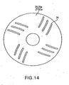
- Figure 14 shows a top view illustration of top view secondary synchronous rotary disk.
- Figure 15 shows a side view illustration of a shaft with a secondary synchronous stator disc splined in the center and the primary synchronous permanent magnet rotary motor on each side of the secondary member which is shown to being guided by a slide type mechanism.
- Figure 16 is a top view illustration of the machine one-piece highly conductive cover that bolts to the rotary ferromagnetic back plate.
- The device for surrounding, guiding and covering the
permanent magnet array 1, comprises aframe 4, preferably made of stainless steel, which is laminated to anotherframe 5, preferably made of a conductive type element such as copper or aluminum or any other highly conductive material. The laminatedframes stainless steel case 6. The desired pole pitch spacing is determined by the dimensions of this double frame andcover ferromagnetic back plate 2. Theback plate 2 has a matching countersunk bolt pattern. The stainless steel portion of theframe 4 provides the surface that mates to theferromagnetic back plate 2. Thisstainless steel surface 4 or the surface of theferromagnetic back plate 2 contains ano'ring seal groove 7 precision machined around the entire perimeter and bolt holes to accept ano'ring seal 7a, preferably made of rubber, to provide a watertight seal when the frame andcover ferromagnetic back plate 2, due to the intolerance of the permanent magnets to aqueous and corrosive environments. - Two means are incorporated into the
frames ferromagnetic back plate 2 for ensuring the precise alignment of thepermanent magnet array 1. The first is provided by the laminatedframes ferromagnetic back plate 2. The depth or elevation of theframes permanent magnet array 1, and the one-piece segmenteddouble frame magnet array 1. The pole pitch spacing between eachindividual magnet 1 will be identical to the spacing of segments of the one-piece double frame/cover back plate 2 contains precision machinedpockets 3 to accept thepermanent magnet array 1. Thecounter sunk pockets 3 are machined to a slight oversized dimension of themagnet 1. Themagnets 1 are preferably attached by means of epoxy adhesive to theferromagnetic back plate 2 within thecountersunk pockets 3. The machinedcountersunk pockets 3 will not allow themagnets 1 to slide back and forth or attract one another, due to their alternating pole arrangement. Therefore, the magnet array I can be attached to theferromagnetic back plate 2 so that the one-piece double frame/case case magnetic array 1 and other external influences such as water, salt mist, corrosive contamination, metal objects and dirt and debris. - The one-piece
conductive frame 5 that is laminated to the one-piecestainless frame 4 will surround the upper portion of eachmagnet 1 such that theconductive frame 5 will enhance the flux field emitted by thepermanent magnet array 1 by at least 5% or greater when introduced to a secondary stator portion. Theconductive frame 5 will also reduce spatial harmonics that commonly occur during transient dynamic motion and high force application. - The above described double frame and
stainless steel case case 11 or machined as such from a solid billet of extruded conductive material. The casting material utilized is a proprietary conductive type alloy. The one-piece cast design 11 acts as a case and frame. Theframe 11 will consist of ladder type segments that will maintain the desired pole pitch spacing between eachmagnet 1. The elevation of the one-piece frame/case 11 will again be determined by the elevation of thepermanent magnet array 1. Thepermanent magnet array 1 will consist of at least two or more permanent magnets with alternating polarity. This one-piececast alloy frame 11 will also act as the shading or dampening frame to reduce spatial harmonics, flux leakage and flux fringing as previously mentioned by at least 5%. The surface of theframe 11 which mates to theferromagnetic back plate 2 is precision machined with ano'ring seal groove 7 to accept ano'ring seal 7a, preferably rubber, that may be the round or square type. Theferromagnetic back plate 2 again contains precision machinedcountersunk pockets 3 to accept thepermanent magnet array 1. Thecountersunk slots 3 will be spaced accordingly to provide the desired pole pitch spacing between eachmagnet 1. Again, the cast alloy or extruded frame/cover 11 may be bolted to theferromagnetic back plate 2 at any given time without damaging or altering the desired pole spacing between the permanent magnet array. - In an embodiment, the invention consists of a one-piece
linear stator rail 25 constructed of at least one layer of conductive material such as brass, copper, aluminum, beryllium copper, titanium or any other highly conductive alloy or material. The above material can be laminated, one on top of the other, as illustrated in Figures 8 & 9. By laminating more than one conductive material, a variable electro-dynamic brake drag will occur along thesecondary stator member 25 as a function of time wherein copper would provide (t1) aluminum (t2) brass (t3). - Figure 8 shows narrow slots cut out at a 5-10 degree angle, the pole pitch spacing, the discrete synchronous current loop, the non-conductive barrier around the inside edge of the slot, the highly permeable steel or ferrite core within the slot and two one-piece dissimilar conductive layers, shown as (t1) aluminum and (t2) copper. Figure 9 illustrates the vertical X & Y axis view of the synchronous linear secondary stator member. The illustration shows narrow slots cut out at a 90 degree angle, the pole pitch spacing, the discrete synchronous current loop, the non-conductive insulation barrier around the inside edge of the slot, the highly permeable steel or ferrite core within the slot and two one-piece dissimilar conductive layers, shown as (t1) copper and (t2) aluminum. Figure 10 illustrates a cutaway vertical X & Y axis view of the preferred embodiment of the braking system, which includes the primary synchronous linear permanent magnet motor with a ferromagnetic back plate and eight alternating negative and positive magnets and the flux path return circuits that travel through the secondary member. The illustration also includes the double-layered synchronous linear secondary stator member showing a cutaway view of the narrow slots and how the pole pitch of the slots, match the pole pitch of the alternating permanent magnets. Figure 11 illustrates an enlarged vertical X & Y axis view of the one-piece synchronous linear secondary stator member having one (enlarged for illustration) narrow slot with a non-conductive insulating barrier around the inside edge of the slot, the highly permeable steel or ferrite core within the slot and the discrete synchronous current loop.
- The
stator 25 has narrow slots cut out along the Y-axis at apre-determined pole pitch 30. Thenarrow slots 31 provide at least two purposes. One purpose is to direct the electrical currents to run in a synchronized anddiscrete pathway 32 along thesecondary stator 25 during transient dynamic motion as the synchronous linear permanent magnet motor enters said stator. The second purpose of the slotting is to allow for the installation of a small highly permeable steel orferrite core 29, when use of such core is desired. However, ferrite core slot inserts are not required. In an embodiment, the steel orferrite core 29 is surrounded by an electricalinsulating type material 28 such asnylon 6/6, fiberglass G-10, fiberglass insulating tape or any other insulating type barrier. Therein the steel orferrite core 29 will not touch the edges of theconductive stator rail 25 once installed. Theinsulated material 28 between the core and the conductive stator will prevent electrical shorts during excitation. The steel orferrite core 29, as shown in figures 8, 9 and 11, is utilized to maintain or increase the magnetic flux between the air gap of the double sided linear synchronous permanent magnetprimary member 1 during high and low speed dynamic excitation. The narrow slots that are cut into thesecondary stator member 25 along the Y-axis are slotted at about a 5 to 10 degree angle or eliminate brake pulsation along the active brake area. The narrow slots may also be slotted at a 90 degree angle along the active braking area as illustrated in figure 9.Narrow slots 31 create a higher electro-dynamic drag coefficient than the use of wide slots. In an example, the secondary synchronouslinear stator member 25 does not consist of any other steel or ferrous material other than the highly permeable steel orferrite core 29 that is utilized within thenarrow slots 31. To reduce initial braking "jerk rate" as the moving vehicle enters the synchronous linearsecondary member 25, a particular number of the highly permeable steel orferrite cores 29 may be removed from the initial entry of the active braking area or left out all together as illustrated in Figures 8-11. - The primary member in an embodiment consists of a double sided linear synchronous motor consisting of at least two permanent magnets of negative and positive polarity situated on opposite sides of the secondary stator member (transverse axis) as illustrated in figure 10, for example.
Magnets 44, 34, 35, 36 as illustrated in figure 10 are arranged so as to face positive andmagnets 45, 37, 38, 39 are arranged so as to face negative. Wherein this arrangement allows aflux return circuit 26 to occur through thesecondary stator member 25. Wherein figure 10 illustrates an eight polepermanent magnet configuration 1. Wherein the pole pitch 27 of thepermanent magnet 1 along the transverse-axis will match thepole pitch 23 of the secondary synchronous stator member along the same transverse-axis, wherein a distinct synchronouselectrical circuit path 32 will occur during transient excitation. The pole pitch of the synchronous primary permanent magnet member 27 and the secondary synchronous stator member 33 will depend on the entry velocity of the object or vehicle being stopped or slowed down. In other words, the electrical frequency of the secondarysynchronous stator member 25 can be tuned to a particular frequency (Hertz) at vehicle entry by expressing,
- Where Tp is the pole pitch of the linear synchronous permanent magnet member in meters and Vs is the entry velocity of the vehicle. f is the frequency produced in Hertz. As the braking force fades or decays, the electrical frequency along the linear secondary
synchronous stator member 25 diminishes accordingly. - The primary synchronous
permanent magnet member 1 may be affixed to the non-stationary vehicle or may be affixed in a stationary manner along the vehicle pathway. As well, the secondarysynchronous stator member 20 may be affixed to the non-stationary vehicle or may be fixed in a stationary manner along the vehicle pathway. - The described synchronous linear permanent magnet braking device has also been designed so as to function in a rotational manner as well. This application would provide a means of energy dissipation by reducing kinetic energy along a rotating shaft, 20, gear assembly, axle or any other rotating device requiring the reduction or total decay of rotational movement.
- The aforementioned linear primary synchronous permanent magnet motor will continue to be arranged so that the alternating positive and negative permanent magnet array will be affixed 360 degrees around a disc shaped ferromagnetic back plate, 1, where in an opposite array of permanent magnets, 4,5,17,14,15,18 face one another in an opposite polarity configuration. This configuration will consist of at least two permanent magnets of alternating polarity. The disc shaped ferromagnetic back plates, 1 will be affixed to a slide assembly, 21. This slide assembly, 21 will allow the opposing disc shaped synchronous permanent magnetic assemblies to remain aligned with one another along the transverse axis. The slides 21 will also allow transverse or perpendicular movement of each opposing back plate thereby allowing for an adjustable magnetic air gap. The disc shaped synchronous permanent magnet assemblies may be controlled and adjusted by means of an air or hydraulic cylinder(s), 22, linear actuators, manual pivoting lever or any other mechanical or electrical means to control or variate the width of the air gap, 24.
- Between the magnetic air gap, 24 of the opposing synchronous permanent magnet array, 4,5,17,14,15,18 will be the secondary synchronous conductive disc, 2. Whereby this disc consists of a single layer or multiple layers of a conductive material. Wherein the multiple layers of conductive material will cause a variable electro-dynamic drag to occur as a function of time throughout the braking cycle. Wherein the synchronous secondary conductive disc, 2 will have slots, 11 cut through a portion of the Y-axis along the active braking area. To reduce braking pulsation during a brake cycle, the slots, 11 will be cut to at least a 1 degree angle, 360 degrees along the transverse axis of the aforementioned disc, 2.
- The invention can also be configured to where the secondary synchronous conductive disc, 2 would be attached in a stationary manner to prevent rotation. The primary synchronous permanent magnet motor would be attached to and rotate with the rotating member. However, the rotating primary synchronous permanent magnet motor would continue to be designed to slide or actuate in a variable manner transversely or perpendicular to the fixed synchronous secondary disc, 2 as illustrated in figure 3.
- The ferromagnetic back plate; 1 of the primary synchronous permanent magnet motor and the hermetically sealed conductive cover that attaches to the ferromagnetic back plate, 1 will be constructed according to the linear version.
Claims (7)
- A primary member of a synchronous permanent magnet motor comprising:(a) a ferromagnetic back plate (2), the ferromagnetic back plate further comprising pockets (3) machined therein to accept a permanent magnet array, said pockets (3) spaced apart at a predetermined pole pitch spacing(b) an array of permanent magnets, the permanent magnets arranged in alternating polarity, said magnets accepted by said pockets, said pockets surrounding the magnets and keeping the magnets in place; and(c) a frame (11) made of a conductive alloy mated to said ferromagnetic back plate, said frame showing ladder-type segments to maintain the desired pole pitch spacing between each magnet.
- The primary member of Claim 1 wherein the frame comprises a frame assembly of a first frame member (4) laminated to a second frame member (5) made of a conductive material.
- The primary member of Claim 1 wherein said back plate is made of a material selected from the group consisting of structural type steel and electrical type steel
- The primary member of Claim 1 wherein said frame is blind drilled and tapped to create a bolt pattern (9) to match a bolt pattern (8) of the back plate.
- The primary member of Claim 1 wherein said back plate further comprises an O ring groove (7) machined into a surface of the back plate, said surface of the back plate facing a surface of the frame.
- The primary member of Claim 1 wherein said frame acts as a damper circuit, and wherein said frame in combination with said back plate surrounds and shades an outside and an upper portion of each magnet, thereby reducing spatial harmonics, leakage flux and flux fringe by at least 5%.
- The primary member of Claim 1 wherein said back plate comprises a bolt pattern, said bolt pattern comprising countersunk bolts surrounding each of said magnets.
Applications Claiming Priority (5)
| Application Number | Priority Date | Filing Date | Title |
|---|---|---|---|
| US38306602P | 2002-05-24 | 2002-05-24 | |
| US383066P | 2002-05-24 | ||
| US39024402P | 2002-06-20 | 2002-06-20 | |
| US390244P | 2002-06-20 | ||
| PCT/US2003/016510 WO2003100943A2 (en) | 2002-05-24 | 2003-05-23 | Fixationi of permanent magnets to secondary of linear machine and linear machine with multiple time constant circuits |
Publications (2)
| Publication Number | Publication Date |
|---|---|
| EP1516407A2 EP1516407A2 (en) | 2005-03-23 |
| EP1516407B1 true EP1516407B1 (en) | 2006-08-23 |
Family
ID=29586976
Family Applications (1)
| Application Number | Title | Priority Date | Filing Date |
|---|---|---|---|
| EP03755491A Expired - Lifetime EP1516407B1 (en) | 2002-05-24 | 2003-05-23 | Primary member of a linear synchronous permanent magnet motor |
Country Status (10)
| Country | Link |
|---|---|
| US (1) | US6930413B2 (en) |
| EP (1) | EP1516407B1 (en) |
| AT (1) | ATE337639T1 (en) |
| AU (1) | AU2003231851B2 (en) |
| BR (1) | BR0311239A (en) |
| CA (1) | CA2487652C (en) |
| DE (1) | DE60307845T2 (en) |
| ES (1) | ES2270086T3 (en) |
| HK (1) | HK1074537A1 (en) |
| WO (1) | WO2003100943A2 (en) |
Families Citing this family (31)
| Publication number | Priority date | Publication date | Assignee | Title |
|---|---|---|---|---|
| CN100440695C (en) * | 2003-12-05 | 2008-12-03 | 财团法人工业技术研究院 | Modular permanent-magnet synchronous linear motor |
| US7458454B2 (en) * | 2004-05-07 | 2008-12-02 | Magnemotion, Inc. | Three-dimensional motion using single-pathway based actuators |
| JP2006174583A (en) * | 2004-12-15 | 2006-06-29 | Fanuc Ltd | Linear motor |
| US20060255679A1 (en) * | 2005-05-13 | 2006-11-16 | Dine Pieter V | Apparatus for pole pieces |
| EP1748636B1 (en) * | 2005-07-28 | 2008-11-19 | Harman Becker Automotive Systems GmbH | Improved communication in passenger compartments |
| DE102005045900B4 (en) * | 2005-09-26 | 2010-12-09 | Siemens Ag | Secondary part of a linear electric machine and method for its production |
| EP1949044B1 (en) * | 2005-10-06 | 2014-05-21 | Micro Motion, Inc. | Magnet assembly |
| DE102006012736A1 (en) * | 2006-03-17 | 2007-09-20 | Siemens Ag | Electric machine |
| CN101075269B (en) * | 2007-06-22 | 2012-04-18 | 广东工业大学 | Method for designing mould cavity |
| US9032880B2 (en) | 2009-01-23 | 2015-05-19 | Magnemotion, Inc. | Transport system powered by short block linear synchronous motors and switching mechanism |
| US8616134B2 (en) | 2009-01-23 | 2013-12-31 | Magnemotion, Inc. | Transport system powered by short block linear synchronous motors |
| US8113310B2 (en) * | 2009-02-12 | 2012-02-14 | General Atomics | Linear motor charged electric vehicle |
| MX348341B (en) | 2009-09-15 | 2017-06-06 | Kpit Cummins Infosystems Ltd * | Motor assistance for a hybrid vehicle based on predicted driving range. |
| WO2011033529A2 (en) | 2009-09-15 | 2011-03-24 | Kpit Cummins Infosystems Ltd. | Motor assistance for a hybrid vehicle based on user input |
| CN102483020B (en) | 2009-09-15 | 2015-03-04 | Kpit技术有限责任公司 | Method of converting vehicle into hybrid vehicle |
| WO2011033528A2 (en) | 2009-09-15 | 2011-03-24 | Kpit Cummins Infosystems Limited | Motor assistance for a hybrid vehicle |
| DE102009048822A1 (en) * | 2009-10-09 | 2011-04-14 | Siemens Aktiengesellschaft | Transport system with electromagnetic brake |
| US8020494B2 (en) | 2009-11-20 | 2011-09-20 | Disney Enterprises, Inc. | Anti-roll back assembly with linear magnetic positioning |
| US20110290161A1 (en) * | 2010-05-27 | 2011-12-01 | Valley Precision, Inc. | Stage with magnetic loading |
| WO2011155022A1 (en) * | 2010-06-08 | 2011-12-15 | 株式会社日立製作所 | Linear motor |
| US20120248898A1 (en) * | 2011-03-29 | 2012-10-04 | Richard Tucker Carlmark | Moving Magnet Actuator Magnet Carrier |
| US8610318B2 (en) * | 2011-03-29 | 2013-12-17 | Bose Corporation | Moving magnet actuator magnet carrier |
| CN104081637B (en) | 2012-02-20 | 2017-06-16 | 株式会社日立制作所 | Linear motor |
| US8716913B2 (en) * | 2012-08-07 | 2014-05-06 | Boulder Wind Power, Inc. | Devices and methods for magnetic pole and back iron retention in electromagnetic machines |
| CN105308835B (en) | 2013-06-20 | 2019-05-14 | 奥的斯电梯公司 | Motor with the rotor with inclination permanent magnet |
| KR102331404B1 (en) | 2013-09-21 | 2021-11-25 | 마그네모션, 인코포레이티드 | Linear motor transport for packaging and other uses |
| US10046644B2 (en) | 2013-10-02 | 2018-08-14 | Velocity Magnetics, Inc. | Solid state energy storage and management system |
| US10476364B2 (en) * | 2016-06-15 | 2019-11-12 | Asm Technology Singapore Pte Ltd | Magnet assembly mounting arrangement for an electromagnetic motor |
| CN107171527B (en) * | 2017-06-09 | 2023-04-18 | 浙江理工大学 | Excitation topological structure of non-uniform block type permanent magnet linear synchronous motor and design method |
| WO2019060644A1 (en) | 2017-09-20 | 2019-03-28 | Roelle Matthew | Auto-braking for an electromagnetic machine |
| US11496075B2 (en) | 2017-10-11 | 2022-11-08 | Velocity Magnetics, Inc. | Using linear synchronous motors for retarding linear motion and conveying systems |
Family Cites Families (16)
| Publication number | Priority date | Publication date | Assignee | Title |
|---|---|---|---|---|
| GB433408A (en) * | 1933-12-07 | 1935-08-14 | Raoul Sarazin | Improvements in electrical devices for the absorption of mechanical energy |
| JPS57151263A (en) * | 1981-03-13 | 1982-09-18 | Mitsubishi Electric Corp | Eddy current generating rotary disc |
| JPS59172967A (en) * | 1983-03-18 | 1984-09-29 | Toshiba Corp | Eddy current brake device |
| US4767954A (en) * | 1986-04-11 | 1988-08-30 | Compact Spindle Bearing Corporation | Solid state commutated linear motor with an ironless multiphase armature |
| US5994798A (en) * | 1998-02-26 | 1999-11-30 | Anorad Corporation | Closed-path linear motor |
| DE4137201A1 (en) * | 1991-11-12 | 1993-05-13 | Intrasys Gmbh | LINEAR MOTOR OR GENERATOR AND STATOR HERE |
| WO1995006949A1 (en) * | 1993-09-01 | 1995-03-09 | Grumman Aerospace Corporation | Superconducting electromagnet for levitation and propulsion of a maglev vehicle |
| DE19503511C5 (en) * | 1995-02-03 | 2010-11-04 | Siemens Ag | Synchronous linear motor |
| DE29506374U1 (en) * | 1995-04-13 | 1996-10-02 | Funex Ag | Amusement device |
| WO1997002647A1 (en) * | 1995-07-03 | 1997-01-23 | Fanuc Ltd | Permanent magnet field pole for linear motors |
| NL1003527C2 (en) | 1996-07-05 | 1998-01-07 | Optische Ind Oede Oude Delftoe | Catheter. |
| CA2318823A1 (en) | 1998-02-25 | 1999-09-02 | Satish C. Wadhawan | Solvent extraction of ferric chloride |
| EP0959549B1 (en) * | 1998-05-22 | 2003-05-07 | Northmag B.V. | Brushless permanent magnet electric motor |
| JP2001025229A (en) * | 1999-07-06 | 2001-01-26 | Nippon Thompson Co Ltd | Slide device incorporating moving coil linear motor |
| MY133384A (en) * | 2000-07-17 | 2007-11-30 | Inventio Ag | Secondary part of a linear motor, method for the production thereof, linear motor with secondary part and use of the linear motor |
| US6703754B1 (en) * | 2001-10-01 | 2004-03-09 | Ametek, Inc. | Electric motor and brush retaining assembly |
-
2003
- 2003-05-23 BR BR0311239-0A patent/BR0311239A/en not_active Application Discontinuation
- 2003-05-23 AU AU2003231851A patent/AU2003231851B2/en not_active Ceased
- 2003-05-23 WO PCT/US2003/016510 patent/WO2003100943A2/en active IP Right Grant
- 2003-05-23 ES ES03755491T patent/ES2270086T3/en not_active Expired - Lifetime
- 2003-05-23 AT AT03755491T patent/ATE337639T1/en active
- 2003-05-23 EP EP03755491A patent/EP1516407B1/en not_active Expired - Lifetime
- 2003-05-23 DE DE60307845T patent/DE60307845T2/en not_active Expired - Lifetime
- 2003-05-23 US US10/444,534 patent/US6930413B2/en not_active Expired - Lifetime
- 2003-05-23 CA CA002487652A patent/CA2487652C/en not_active Expired - Lifetime
-
2005
- 2005-09-21 HK HK05108287A patent/HK1074537A1/en not_active IP Right Cessation
Also Published As
| Publication number | Publication date |
|---|---|
| AU2003231851B2 (en) | 2007-01-04 |
| HK1074537A1 (en) | 2005-11-11 |
| DE60307845T2 (en) | 2007-03-08 |
| WO2003100943A2 (en) | 2003-12-04 |
| CA2487652C (en) | 2008-12-09 |
| AU2003231851A1 (en) | 2003-12-12 |
| BR0311239A (en) | 2005-02-22 |
| ES2270086T3 (en) | 2007-04-01 |
| EP1516407A2 (en) | 2005-03-23 |
| CA2487652A1 (en) | 2003-12-04 |
| WO2003100943A3 (en) | 2004-04-15 |
| US6930413B2 (en) | 2005-08-16 |
| ATE337639T1 (en) | 2006-09-15 |
| US20040070286A1 (en) | 2004-04-15 |
| DE60307845D1 (en) | 2006-10-05 |
Similar Documents
| Publication | Publication Date | Title |
|---|---|---|
| EP1516407B1 (en) | Primary member of a linear synchronous permanent magnet motor | |
| US9620998B2 (en) | Motor cooling and eddy current suppression structure | |
| CA1213636A (en) | Limited angle torque motor with magnetic centering and stops | |
| US7145271B2 (en) | High performance linear motor and magnet assembly therefor | |
| US6664880B2 (en) | Inductrack magnet configuration | |
| US6956312B2 (en) | Brushless DC motor and method of manufacturing brushless DC motor | |
| US7859142B2 (en) | Woodworking machine with linear direct drive | |
| US8922068B2 (en) | Linear drive motor with improved bearing system | |
| US20030005849A1 (en) | Inductrack magnet configuration | |
| CA2142886A1 (en) | Electromagnetic transducer | |
| CN111355323A (en) | Disk type motor rotor with pole shoe composite magnetic pole structure | |
| US8791608B2 (en) | Primary for linear drive motor with solid steel stacks | |
| EP0941019B1 (en) | Hybrid wiggler | |
| US7538456B2 (en) | Moving magnet type linear actuator | |
| CN211655867U (en) | Disk type motor rotor with pole shoe composite magnetic pole structure | |
| Bauer et al. | Analytical Calculation of Eddy Current related Losses and Parasitic Torque in PCB Windings | |
| JPWO2019186832A1 (en) | Rotary electric machine and elevator door device using the same | |
| EP0303703A1 (en) | Rotor structure of motor having permanent magnet | |
| JPH0587187A (en) | Magnetic damper device | |
| JPH0287505A (en) | Magnetic field generating equipment for mri use | |
| JPS60131071A (en) | Linear motor | |
| Okada et al. | Proposal of flux concentrated radial and axial magnetic bearings | |
| FI20195489A1 (en) | A linear electric machine | |
| Overstreet et al. | Design and Testing of a Permanent Magnet Biased Active Magnetic Bearing | |
| GB1110340A (en) | Improvements in dynamoelectric machines |
Legal Events
| Date | Code | Title | Description |
|---|---|---|---|
| PUAI | Public reference made under article 153(3) epc to a published international application that has entered the european phase |
Free format text: ORIGINAL CODE: 0009012 |
|
| 17P | Request for examination filed |
Effective date: 20041223 |
|
| AK | Designated contracting states |
Kind code of ref document: A2 Designated state(s): AT BE BG CH CY CZ DE DK EE ES FI FR GB GR HU IE IT LI LU MC NL PT RO SE SI SK TR |
|
| AX | Request for extension of the european patent |
Extension state: AL LT LV MK |
|
| DAX | Request for extension of the european patent (deleted) | ||
| REG | Reference to a national code |
Ref country code: HK Ref legal event code: DE Ref document number: 1074537 Country of ref document: HK |
|
| GRAP | Despatch of communication of intention to grant a patent |
Free format text: ORIGINAL CODE: EPIDOSNIGR1 |
|
| RTI1 | Title (correction) |
Free format text: PRIMARY MEMBER OF A LINEAR SYNCHRONOUS PERMANENT MAGNET MOTOR |
|
| GRAS | Grant fee paid |
Free format text: ORIGINAL CODE: EPIDOSNIGR3 |
|
| RAP1 | Party data changed (applicant data changed or rights of an application transferred) |
Owner name: VELOCITY MAGNETICS, INC. |
|
| GRAA | (expected) grant |
Free format text: ORIGINAL CODE: 0009210 |
|
| AK | Designated contracting states |
Kind code of ref document: B1 Designated state(s): AT BE BG CH CY CZ DE DK EE ES FI FR GB GR HU IE IT LI LU MC NL PT RO SE SI SK TR |
|
| PG25 | Lapsed in a contracting state [announced via postgrant information from national office to epo] |
Ref country code: IT Free format text: LAPSE BECAUSE OF FAILURE TO SUBMIT A TRANSLATION OF THE DESCRIPTION OR TO PAY THE FEE WITHIN THE PRESCRIBED TIME-LIMIT;WARNING: LAPSES OF ITALIAN PATENTS WITH EFFECTIVE DATE BEFORE 2007 MAY HAVE OCCURRED AT ANY TIME BEFORE 2007. THE CORRECT EFFECTIVE DATE MAY BE DIFFERENT FROM THE ONE RECORDED. Effective date: 20060823 Ref country code: BE Free format text: LAPSE BECAUSE OF FAILURE TO SUBMIT A TRANSLATION OF THE DESCRIPTION OR TO PAY THE FEE WITHIN THE PRESCRIBED TIME-LIMIT Effective date: 20060823 Ref country code: RO Free format text: LAPSE BECAUSE OF FAILURE TO SUBMIT A TRANSLATION OF THE DESCRIPTION OR TO PAY THE FEE WITHIN THE PRESCRIBED TIME-LIMIT Effective date: 20060823 Ref country code: FI Free format text: LAPSE BECAUSE OF FAILURE TO SUBMIT A TRANSLATION OF THE DESCRIPTION OR TO PAY THE FEE WITHIN THE PRESCRIBED TIME-LIMIT Effective date: 20060823 Ref country code: SI Free format text: LAPSE BECAUSE OF FAILURE TO SUBMIT A TRANSLATION OF THE DESCRIPTION OR TO PAY THE FEE WITHIN THE PRESCRIBED TIME-LIMIT Effective date: 20060823 Ref country code: SK Free format text: LAPSE BECAUSE OF FAILURE TO SUBMIT A TRANSLATION OF THE DESCRIPTION OR TO PAY THE FEE WITHIN THE PRESCRIBED TIME-LIMIT Effective date: 20060823 Ref country code: CZ Free format text: LAPSE BECAUSE OF FAILURE TO SUBMIT A TRANSLATION OF THE DESCRIPTION OR TO PAY THE FEE WITHIN THE PRESCRIBED TIME-LIMIT Effective date: 20060823 |
|
| REG | Reference to a national code |
Ref country code: GB Ref legal event code: FG4D |
|
| REG | Reference to a national code |
Ref country code: CH Ref legal event code: EP |
|
| REG | Reference to a national code |
Ref country code: IE Ref legal event code: FG4D |
|
| REF | Corresponds to: |
Ref document number: 60307845 Country of ref document: DE Date of ref document: 20061005 Kind code of ref document: P |
|
| REG | Reference to a national code |
Ref country code: HK Ref legal event code: GR Ref document number: 1074537 Country of ref document: HK |
|
| PG25 | Lapsed in a contracting state [announced via postgrant information from national office to epo] |
Ref country code: DK Free format text: LAPSE BECAUSE OF FAILURE TO SUBMIT A TRANSLATION OF THE DESCRIPTION OR TO PAY THE FEE WITHIN THE PRESCRIBED TIME-LIMIT Effective date: 20061123 Ref country code: SE Free format text: LAPSE BECAUSE OF FAILURE TO SUBMIT A TRANSLATION OF THE DESCRIPTION OR TO PAY THE FEE WITHIN THE PRESCRIBED TIME-LIMIT Effective date: 20061123 Ref country code: BG Free format text: LAPSE BECAUSE OF FAILURE TO SUBMIT A TRANSLATION OF THE DESCRIPTION OR TO PAY THE FEE WITHIN THE PRESCRIBED TIME-LIMIT Effective date: 20061123 |
|
| REG | Reference to a national code |
Ref country code: CH Ref legal event code: NV Representative=s name: PATENTANWAELTE SCHAAD, BALASS, MENZL & PARTNER AG |
|
| PG25 | Lapsed in a contracting state [announced via postgrant information from national office to epo] |
Ref country code: PT Free format text: LAPSE BECAUSE OF FAILURE TO SUBMIT A TRANSLATION OF THE DESCRIPTION OR TO PAY THE FEE WITHIN THE PRESCRIBED TIME-LIMIT Effective date: 20070125 |
|
| ET | Fr: translation filed | ||
| REG | Reference to a national code |
Ref country code: ES Ref legal event code: FG2A Ref document number: 2270086 Country of ref document: ES Kind code of ref document: T3 |
|
| PLBE | No opposition filed within time limit |
Free format text: ORIGINAL CODE: 0009261 |
|
| STAA | Information on the status of an ep patent application or granted ep patent |
Free format text: STATUS: NO OPPOSITION FILED WITHIN TIME LIMIT |
|
| 26N | No opposition filed |
Effective date: 20070524 |
|
| PG25 | Lapsed in a contracting state [announced via postgrant information from national office to epo] |
Ref country code: MC Free format text: LAPSE BECAUSE OF NON-PAYMENT OF DUE FEES Effective date: 20070531 |
|
| PG25 | Lapsed in a contracting state [announced via postgrant information from national office to epo] |
Ref country code: GR Free format text: LAPSE BECAUSE OF FAILURE TO SUBMIT A TRANSLATION OF THE DESCRIPTION OR TO PAY THE FEE WITHIN THE PRESCRIBED TIME-LIMIT Effective date: 20061124 |
|
| PG25 | Lapsed in a contracting state [announced via postgrant information from national office to epo] |
Ref country code: IE Free format text: LAPSE BECAUSE OF NON-PAYMENT OF DUE FEES Effective date: 20070523 |
|
| PG25 | Lapsed in a contracting state [announced via postgrant information from national office to epo] |
Ref country code: EE Free format text: LAPSE BECAUSE OF FAILURE TO SUBMIT A TRANSLATION OF THE DESCRIPTION OR TO PAY THE FEE WITHIN THE PRESCRIBED TIME-LIMIT Effective date: 20060823 |
|
| PG25 | Lapsed in a contracting state [announced via postgrant information from national office to epo] |
Ref country code: LU Free format text: LAPSE BECAUSE OF NON-PAYMENT OF DUE FEES Effective date: 20070523 Ref country code: CY Free format text: LAPSE BECAUSE OF FAILURE TO SUBMIT A TRANSLATION OF THE DESCRIPTION OR TO PAY THE FEE WITHIN THE PRESCRIBED TIME-LIMIT Effective date: 20060823 |
|
| PG25 | Lapsed in a contracting state [announced via postgrant information from national office to epo] |
Ref country code: TR Free format text: LAPSE BECAUSE OF FAILURE TO SUBMIT A TRANSLATION OF THE DESCRIPTION OR TO PAY THE FEE WITHIN THE PRESCRIBED TIME-LIMIT Effective date: 20060823 Ref country code: HU Free format text: LAPSE BECAUSE OF FAILURE TO SUBMIT A TRANSLATION OF THE DESCRIPTION OR TO PAY THE FEE WITHIN THE PRESCRIBED TIME-LIMIT Effective date: 20070224 |
|
| REG | Reference to a national code |
Ref country code: FR Ref legal event code: PLFP Year of fee payment: 14 |
|
| REG | Reference to a national code |
Ref country code: FR Ref legal event code: PLFP Year of fee payment: 15 |
|
| REG | Reference to a national code |
Ref country code: FR Ref legal event code: PLFP Year of fee payment: 16 |
|
| PGFP | Annual fee paid to national office [announced via postgrant information from national office to epo] |
Ref country code: NL Payment date: 20220518 Year of fee payment: 20 |
|
| PGFP | Annual fee paid to national office [announced via postgrant information from national office to epo] |
Ref country code: IT Payment date: 20220531 Year of fee payment: 20 Ref country code: GB Payment date: 20220524 Year of fee payment: 20 Ref country code: FR Payment date: 20220524 Year of fee payment: 20 Ref country code: ES Payment date: 20220617 Year of fee payment: 20 Ref country code: DE Payment date: 20220517 Year of fee payment: 20 |
|
| PGFP | Annual fee paid to national office [announced via postgrant information from national office to epo] |
Ref country code: CH Payment date: 20220523 Year of fee payment: 20 Ref country code: AT Payment date: 20220517 Year of fee payment: 20 |
|
| REG | Reference to a national code |
Ref country code: DE Ref legal event code: R071 Ref document number: 60307845 Country of ref document: DE |
|
| REG | Reference to a national code |
Ref country code: NL Ref legal event code: MK Effective date: 20230522 |
|
| REG | Reference to a national code |
Ref country code: CH Ref legal event code: PL |
|
| REG | Reference to a national code |
Ref country code: ES Ref legal event code: FD2A Effective date: 20230601 |
|
| REG | Reference to a national code |
Ref country code: GB Ref legal event code: PE20 Expiry date: 20230522 |
|
| REG | Reference to a national code |
Ref country code: AT Ref legal event code: MK07 Ref document number: 337639 Country of ref document: AT Kind code of ref document: T Effective date: 20230523 |
|
| PG25 | Lapsed in a contracting state [announced via postgrant information from national office to epo] |
Ref country code: ES Free format text: LAPSE BECAUSE OF EXPIRATION OF PROTECTION Effective date: 20230524 |
|
| PG25 | Lapsed in a contracting state [announced via postgrant information from national office to epo] |
Ref country code: GB Free format text: LAPSE BECAUSE OF EXPIRATION OF PROTECTION Effective date: 20230522 |