EP0754366B1 - Verfahren zur herstellung eines synchron-linearmotors - Google Patents
Verfahren zur herstellung eines synchron-linearmotors Download PDFInfo
- Publication number
- EP0754366B1 EP0754366B1 EP96900964A EP96900964A EP0754366B1 EP 0754366 B1 EP0754366 B1 EP 0754366B1 EP 96900964 A EP96900964 A EP 96900964A EP 96900964 A EP96900964 A EP 96900964A EP 0754366 B1 EP0754366 B1 EP 0754366B1
- Authority
- EP
- European Patent Office
- Prior art keywords
- permanent magnets
- locating
- individual frames
- pins
- carrier plate
- Prior art date
- Legal status (The legal status is an assumption and is not a legal conclusion. Google has not performed a legal analysis and makes no representation as to the accuracy of the status listed.)
- Expired - Lifetime
Links
Images

Classifications
-
- H—ELECTRICITY
- H02—GENERATION; CONVERSION OR DISTRIBUTION OF ELECTRIC POWER
- H02K—DYNAMO-ELECTRIC MACHINES
- H02K41/00—Propulsion systems in which a rigid body is moved along a path due to dynamo-electric interaction between the body and a magnetic field travelling along the path
- H02K41/02—Linear motors; Sectional motors
- H02K41/03—Synchronous motors; Motors moving step by step; Reluctance motors
- H02K41/031—Synchronous motors; Motors moving step by step; Reluctance motors of the permanent magnet type
-
- H—ELECTRICITY
- H02—GENERATION; CONVERSION OR DISTRIBUTION OF ELECTRIC POWER
- H02K—DYNAMO-ELECTRIC MACHINES
- H02K41/00—Propulsion systems in which a rigid body is moved along a path due to dynamo-electric interaction between the body and a magnetic field travelling along the path
- H02K41/02—Linear motors; Sectional motors
- H02K41/03—Synchronous motors; Motors moving step by step; Reluctance motors
-
- H—ELECTRICITY
- H02—GENERATION; CONVERSION OR DISTRIBUTION OF ELECTRIC POWER
- H02K—DYNAMO-ELECTRIC MACHINES
- H02K1/00—Details of the magnetic circuit
- H02K1/06—Details of the magnetic circuit characterised by the shape, form or construction
- H02K1/12—Stationary parts of the magnetic circuit
- H02K1/17—Stator cores with permanent magnets
-
- H—ELECTRICITY
- H02—GENERATION; CONVERSION OR DISTRIBUTION OF ELECTRIC POWER
- H02K—DYNAMO-ELECTRIC MACHINES
- H02K1/00—Details of the magnetic circuit
- H02K1/06—Details of the magnetic circuit characterised by the shape, form or construction
- H02K1/22—Rotating parts of the magnetic circuit
- H02K1/27—Rotor cores with permanent magnets
Definitions
- the invention relates to a method for producing a synchronous linear motor with one Winding provided primary part and a secondary part, which consists of a elongated, ferromagnetic carrier plate exists on each a permanent magnet enclosing a parallel gap to one another are.
- the invention has for its object in a synchronous linear motor, fully magnetized Permanent magnets with low construction costs and with high precision on To attach secondary part or to the support plate.
- This object is achieved according to the invention in that between the Permanent magnets corresponding to the pitch pattern of the synchronous linear motor Spacers made of non-magnetic material can be arranged.
- the spacer elements can consist of two in the carrier plate side by side arranged spacers exist. Because the in a sintering process permanent magnets are very brittle, it can be advantageous instead of essentially a point load causing spacer pins to attach crossbars to which the Permanent magnets lie in their entire width.
- cross bars and the lateral positioning strips to a one-piece, ladder-like Positioning structure can be summarized.
- the spacer elements exist one or more permanent magnets each from individual frames enclose.
- These individual frames are preferably with centering devices, for example with centering wedge-shaped projections and recesses, so that due to the pulling force two adjacent permanent magnets self-centering the individual frames be pressed together and thus in their entirety to an exact straight and stable conductor structure.
- centering devices for example with centering wedge-shaped projections and recesses
- the permanent magnets made of very brittle and susceptible to corrosion Material exist and on the other hand only a small part are covered by the primary part, it is necessary to open the to protect lying areas of the permanent magnets.
- This is it advantageous to protect the permanent magnets with a cover plate, the is provided on the sides with folds that the permanent magnets on their Side surfaces directly or their side positioning elements, e.g. the side strips, the side positioning pins or the individual frames embrace.
- the cover plate is due to the spring effect of the folds connected to the secondary part and forms a reliable Protection against mechanical and corrosive damage.
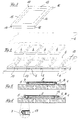
- FIG. 1 shows the carrier plate 1 of the secondary part of a synchronous linear motor with cross bars 2 made of non-magnetic material.
- the cross bars 2 are attached by means of pins 3.
- the pins 3 act as spacer elements for the permanent magnets 4.
- the cross bars 2 are exactly according to the pole pitch of the synchronous linear motor arranged.
- the permanent magnets are between the cross bars 2 4 inserted and glued to the support plate 1.
- To the side Fixing the permanent magnets 4 are lateral positioning pins 5 arranged. After the permanent magnets 4 have been glued, they are joined together of the cover plate 6 consisting of a thin sheet covered, which too has folds 7 and 8 on both sides, which are under spring tension both sides of the permanent magnets 4 can be clamped.
- FIG. 2 corresponds to the embodiment according to FIG. 1, however, are in addition to the side positioning pins Positioning strips 11 and 12 arranged.
- FIG. 3 shows a single frame 13 as a further exemplary embodiment a spacer. 4 are several of these individual frames 13 to a ladder-like holding structure for the permanent magnets 4 summarized. Each individual frame 13 has Centering devices, which on the contact sides 14 and 15 of the Single frame 13 formed wedge-shaped lugs 16 and accordingly there are wedge-shaped bevels 17.
- the Single frame 13 Under the effect of the mutual magnetic attraction the permanent magnet 4 pressed against each other while doing so aligned to a stable straight line by means of the centering devices Holding structure put together.
- the holding structure ensures sticking the permanent magnet 4 for exact adherence to the pole pitch and remains as a lost template on the carrier plate.
- FIG. 5 shows a cross section through a fully assembled secondary part 1 with permanent magnets glued to the carrier plate 1 4 and lateral positioning pins 5. Grips around the cover plate 6 laterally the permanent magnets 4 and is resilient against the Positioning pins 5 pressed folds 7 and 8 attached.
- FIG. 6 shows a cross section through a fully assembled secondary part 4, in which the individual frame 13 from the cover plate 6 are covered.
Landscapes
- Engineering & Computer Science (AREA)
- Power Engineering (AREA)
- Physics & Mathematics (AREA)
- Chemical & Material Sciences (AREA)
- Combustion & Propulsion (AREA)
- Electromagnetism (AREA)
- Linear Motors (AREA)
- Control Of Ac Motors In General (AREA)
- Control Of Motors That Do Not Use Commutators (AREA)
- Synchronous Machinery (AREA)
Description
- Fig. 1
- die perspektivische Ansicht der Einzelbauteile eines Sekundärteils,
- Fig. 2
- die Ansicht des Sekundärteils gemäß Fig. 1 mit seitlichen Positionierleisten,
- Fig. 3
- die Darstellung eines Einzelrahmens,
- Fig. 4
- die Darstellung mehrerer auf der Trägerplatte des Sekundärteils befestigter Einzelrahmen,
- Fig. 5
- den Querschnitt durch ein Sekundärteil mit Abdeckblech gemäß Fig. 1 und
- Fig. 6
- den Querschnitt durch ein Sekundärteil gemäß Fig. 4.
Claims (15)
- Verfahren zur Herstellung eines Synchron-Linearmotors mit einem mit einer Wicklung versehenen Primärteil und einem Sekundärteil, das aus einer langgestreckten ferromagnetischen Trägerplatte besteht, auf der jeweils einen Parallelspalt zueinander einschließende Permanentmagnete festgeklebt werden, dadurch gekennzeichnet, dass zwischen den fertig aufmagnetisierten Permanentmagneten (4) dem Polteilungsrastermaß des Synchron-Linearmotors entsprechende Distanzelemente aus unmagnetischem Material angeordnet werden.
- Verfahren nach Anspruch 1, dadurch gekennzeichnet, dass in der Trägerplatte Stifte (3) als Distanzelemente befestigt werden.
- Verfahren nach Anspruch 2, dadurch gekennzeichnet, dass als Distanzelemente Quersprossen (2) angeordnet werden, die mittels der Stifte (3) fixiert werden.
- Verfahren nach einem der Ansprüche 1 bis 3, dadurch gekennzeichnet, dass die Permanentmagnete (4) in seitlicher Richtung durch beidseitig angeordnete Positionierstifte (5) positioniert werden.
- Verfahren nach einem der Ansprüche 1 bis 4, dadurch gekennzeichnet, dass die Positionierung der Permanentmagnete (4) in seitlicher Richtung durch beidseitig angeordnete Positionierleisten (11,12) erfolgt.
- Verfahren nach einem der Ansprüche 4 oder 5, dadurch gekennzeichnet, dass die Positionierleisten (11,12) mittels der Positionierstifte (5) auf der Trägerplatte fixiert werden.
- Verfahren nach den Ansprüchen 3, 5 und 6, dadurch gekennzeichnet, dass die Quersprossen (2) und die Positionierleisten (11, 12) aus einer einstückigen Positionierstruktur bestehen.
- Verfahren nach Anspruch 7, dadurch gekennzeichnet, dass die Distanzelemente aus jeweils einem oder mehreren Permanentmagnete (4) einschließenden einstückigen Einzelrahmen (13) bestehen.
- Verfahren nach Anspruch 8, dadurch gekennzeichnet, dass die Einzelrahmen (13) Zentriereinrichtungen ausgeformt haben, die zentrierend und in Fluchtung ausrichtend ineinandergreifend angeordnet werden.
- Verfahren nach Anspruch 9, dadurch gekennzeichnet, dass die Zentriereinrichtungen aus an der Außenseite der Kontaktseiten (14,15) eines jeden Einzelrahmens (13) bestehenden keilförmigen Nasen (16) bestehen, die in entsprechend keilförmig ausgebildete Abschrägungen (17) des benachbarten Einzelrahmens (13) eingreifen.
- Verfahren nach einem der Ansprüche 8 bis 10, dadurch gekennzeichnet, dass die Einzelrahmen (13) Kunststoffspritzgießteile sind.
- Verfahren nach Anspruch 10, dadurch gekennzeichnet, dass die Einzelrahmen (13) durch seitlich an der Trägerplatte (1) angeordnete Positionierstifte (5) fixiert werden.
- Verfahren nach einem der Ansprüche 1 bis 12, dadurch gekennzeichnet, dass die Permanentmagnete (4) mittels einer zu beiden Seiten der Permanentmagnete (4) verankerten Abdeckplatte (6) abgedeckt werden.
- Verfahren nach Anspruch 13, dadurch gekennzeichnet, dass die Abdeckplatte (6) seitlich mit Falzen (7,8) versehen ist, die die Permanentmagnete (4) und gegebenenfalls die Positionierelemente seitlich umgreifen.
- Verfahren nach Anspruch 14, dadurch gekennzeichnet, dass die Falze (7,8) unter Federvorspannung an den Permanentmagneten (4) und gegebenenfalls an den Positionierelementen anliegen.
Applications Claiming Priority (3)
| Application Number | Priority Date | Filing Date | Title |
|---|---|---|---|
| DE19503511 | 1995-02-03 | ||
| DE19503511A DE19503511C5 (de) | 1995-02-03 | 1995-02-03 | Synchron-Linearmotor |
| PCT/EP1996/000172 WO1996024189A1 (de) | 1995-02-03 | 1996-01-17 | Synchron-linearmotor |
Publications (3)
| Publication Number | Publication Date |
|---|---|
| EP0754366A1 EP0754366A1 (de) | 1997-01-22 |
| EP0754366B1 true EP0754366B1 (de) | 2002-06-19 |
| EP0754366B2 EP0754366B2 (de) | 2008-08-20 |
Family
ID=7753087
Family Applications (1)
| Application Number | Title | Priority Date | Filing Date |
|---|---|---|---|
| EP96900964A Expired - Lifetime EP0754366B2 (de) | 1995-02-03 | 1996-01-17 | Verfahren zur herstellung eines synchron-linearmotors |
Country Status (6)
| Country | Link |
|---|---|
| US (1) | US5952742A (de) |
| EP (1) | EP0754366B2 (de) |
| JP (1) | JPH09511380A (de) |
| KR (1) | KR970702609A (de) |
| DE (3) | DE19503511C5 (de) |
| WO (1) | WO1996024189A1 (de) |
Cited By (4)
| Publication number | Priority date | Publication date | Assignee | Title |
|---|---|---|---|---|
| CN103326535A (zh) * | 2012-03-19 | 2013-09-25 | 发那科株式会社 | 具有防止磁铁位置偏移作用的直线电动机用磁铁板 |
| US9771000B2 (en) | 2009-01-23 | 2017-09-26 | Magnemotion, Inc. | Short block linear synchronous motors and switching mechanisms |
| US9802507B2 (en) | 2013-09-21 | 2017-10-31 | Magnemotion, Inc. | Linear motor transport for packaging and other uses |
| US10112777B2 (en) | 2009-01-23 | 2018-10-30 | Magnemotion, Inc. | Transport system powered by short block linear synchronous motors |
Families Citing this family (50)
| Publication number | Priority date | Publication date | Assignee | Title |
|---|---|---|---|---|
| DE19643518A1 (de) * | 1996-07-08 | 1998-01-22 | Pasim Mikrosystemtechnik Gmbh | Linearantrieb und Verfahren zur Herstellung einer Passiveinheit eines Linearantriebs, sowie Vorrichtung zur Durchführung des Verfahrens |
| DE19838132B4 (de) * | 1998-08-21 | 2008-04-10 | Siemens Ag | Synchronlinearmotor |
| DE19853250B4 (de) * | 1998-11-18 | 2012-02-02 | Siemens Ag | Sekundärteil für einen Linearmotor |
| DE19936064B4 (de) * | 1999-07-30 | 2011-07-07 | Siemens AG, 80333 | Sekundärteil für einen Linearmotor und Linearmotor sowie Verfahren zur Herstellung eines Sekundärteils |
| US6365993B1 (en) * | 2000-04-07 | 2002-04-02 | Eaton Corporation | Round linear actuator utilizing flat permanent magnets |
| MY133384A (en) | 2000-07-17 | 2007-11-30 | Inventio Ag | Secondary part of a linear motor, method for the production thereof, linear motor with secondary part and use of the linear motor |
| CH695153A5 (de) * | 2000-08-31 | 2005-12-30 | Etel Sa | Baueinheit eines Linearmotors und Verfahren zur Montage dieser Baueinheit. |
| WO2003100943A2 (en) * | 2002-05-24 | 2003-12-04 | Velocity Magnetics, Inc. | Fixationi of permanent magnets to secondary of linear machine and linear machine with multiple time constant circuits |
| US6936937B2 (en) * | 2002-06-14 | 2005-08-30 | Sunyen Co., Ltd. | Linear electric generator having an improved magnet and coil structure, and method of manufacture |
| US20060011093A1 (en) * | 2002-07-26 | 2006-01-19 | Viggo Jensen | Conveyor and a method of providing a driving force to a conveyor |
| AU2003281676A1 (en) | 2002-07-26 | 2004-02-16 | Crisplant A/S | A conveyor and a method of providing a driving force to a conveyor |
| US6943508B2 (en) | 2002-09-23 | 2005-09-13 | Otis Elevator Company | Tubular linear synchronous motor control for elevator doors |
| JP4521221B2 (ja) * | 2004-05-18 | 2010-08-11 | 日本トムソン株式会社 | 可動マグネット型リニアモータを内蔵したスライド装置 |
| US8727078B2 (en) | 2004-05-28 | 2014-05-20 | Velocity Magnetics, Inc. | Selectively incrementally actuated linear eddy current braking system |
| JP2006174583A (ja) * | 2004-12-15 | 2006-06-29 | Fanuc Ltd | リニアモータ |
| WO2007116505A1 (ja) * | 2006-03-31 | 2007-10-18 | Hitachi, Ltd. | リニアモータ |
| JPWO2007116508A1 (ja) * | 2006-03-31 | 2009-08-20 | 株式会社日立製作所 | リニアモータ |
| DE102006022191A1 (de) * | 2006-05-12 | 2007-11-15 | Rovema - Verpackungsmaschinen Gmbh | Beutelmaschine für Verpackungszwecke |
| FR2903823B1 (fr) * | 2006-07-12 | 2008-09-05 | Messier Dowty Sa | Element actif de machine electromagnetique, procede de fabrication d'un tel element actif, et machine electromagnetique comportant un tel element actif. |
| DE102006048966A1 (de) * | 2006-10-17 | 2008-04-30 | Siemens Ag | Magnetmodul für eine permanentmagneterregte elektrische Maschine |
| US8598761B2 (en) * | 2007-05-03 | 2013-12-03 | In Motion Technologies Pty., Ltd. | Rotor magnet positioning device |
| US8967051B2 (en) | 2009-01-23 | 2015-03-03 | Magnemotion, Inc. | Transport system powered by short block linear synchronous motors and switching mechanism |
| ES2387433B1 (es) * | 2009-05-28 | 2013-08-08 | Gamesa Innovation & Technology, S.L. | Metodo de ensamblaje de imanes en generadores y motores de turbinas eolicas y consecuente ensamblaje de imanes. |
| EP2483993A2 (de) | 2009-09-29 | 2012-08-08 | Siemens Aktiengesellschaft | Rotor |
| DE102010041585A1 (de) | 2010-09-29 | 2012-03-29 | Siemens Aktiengesellschaft | Rotor einer elektrischen Maschine |
| JP5536151B2 (ja) | 2011-08-25 | 2014-07-02 | ファナック株式会社 | リニアモータ用磁石板の製造方法 |
| EP2574821B1 (de) | 2011-09-30 | 2013-10-30 | Siemens Aktiengesellschaft | Aktiver Schwingungsdämpfer ohne direkte Beschleunigungserfassung |
| DE102012025324A1 (de) * | 2012-12-22 | 2014-06-26 | Festo Ag & Co. Kg | Stator für einen Lineardirektantrieb und elektrodynamisches Antriebssystem |
| CN104981969B (zh) * | 2013-02-20 | 2016-12-07 | 三菱电机株式会社 | 可动件及具备该可动件的线性电动机 |
| EP2955824B1 (de) | 2014-06-11 | 2017-05-31 | Etel S. A.. | Sekundärteil eines Synchronmotors mit einer Schutzvorrichtung für Magnete |
| EP3032724B1 (de) | 2014-12-11 | 2020-05-13 | Siemens Aktiengesellschaft | Sekundärteil mit Schablone |
| US10170953B2 (en) | 2015-10-02 | 2019-01-01 | E-Circuit Motors, Inc. | Planar composite structures and assemblies for axial flux motors and generators |
| US9673684B2 (en) | 2015-10-02 | 2017-06-06 | E-Circuit Motors, Inc. | Structures and methods for thermal management in printed circuit board stators |
| US9800109B2 (en) | 2015-10-02 | 2017-10-24 | E-Circuit Motors, Inc. | Structures and methods for controlling losses in printed circuit boards |
| US11527933B2 (en) | 2015-10-02 | 2022-12-13 | E-Circuit Motors, Inc. | Stator and rotor design for periodic torque requirements |
| US9859763B2 (en) | 2015-10-02 | 2018-01-02 | E-Circuit Motors, Inc. | Structures and methods for controlling losses in printed circuit boards |
| US11121614B2 (en) | 2017-06-05 | 2021-09-14 | E-Circuit Motors, Inc. | Pre-warped rotors for control of magnet-stator gap in axial flux machines |
| US9673688B2 (en) | 2015-10-02 | 2017-06-06 | E-Circuit Motors, Inc. | Apparatus and method for forming a magnet assembly |
| EP3232550A1 (de) * | 2016-04-12 | 2017-10-18 | Robert Bosch Gmbh | Sekundärteil eines linearmotors |
| US10476364B2 (en) * | 2016-06-15 | 2019-11-12 | Asm Technology Singapore Pte Ltd | Magnet assembly mounting arrangement for an electromagnetic motor |
| US10686355B2 (en) * | 2016-07-15 | 2020-06-16 | Magnemotion, Inc. | Transport system puck assembly |
| US11005322B2 (en) | 2017-06-05 | 2021-05-11 | E-Circuit Motors, Inc. | Rotor assemblies for axial flux machines |
| US11831211B2 (en) | 2017-06-05 | 2023-11-28 | E-Circuit Motors, Inc. | Stator and rotor design for periodic torque requirements |
| EP3661033A1 (de) * | 2018-11-27 | 2020-06-03 | B&R Industrial Automation GmbH | Transporteinrichtung in form eines langstatorlinearmotors |
| EP3719962A1 (de) | 2019-04-01 | 2020-10-07 | LIM-Tech Limited | Elektromotorische maschine |
| DE202020106227U1 (de) * | 2020-10-30 | 2022-02-01 | Schunk Electronic Solutions Gmbh | Sekundärteil für einen Linearmotor, Linearmotor und Baukasten für einen Linearmotor mit Magnetkörpern und Ersatzkörpern |
| JP7784674B2 (ja) | 2021-02-17 | 2025-12-12 | イー-サーキット モーターズ, インコーポレイテッド | 軸方向磁束機械のための平面固定子構成 |
| MX2024001426A (es) | 2021-07-30 | 2024-05-14 | E Circuit Motors Inc | Placas de circuito impreso rellenas de material magnetico y estatores de placas de circuito impreso. |
| US11336130B1 (en) | 2021-08-17 | 2022-05-17 | E-Circuit Motors, Inc. | Low-loss planar winding configurations for an axial flux machine |
| WO2024013987A1 (ja) * | 2022-07-15 | 2024-01-18 | ファナック株式会社 | リニアモーター用磁石板 |
Family Cites Families (19)
| Publication number | Priority date | Publication date | Assignee | Title |
|---|---|---|---|---|
| US2463936A (en) * | 1946-03-21 | 1949-03-08 | Chance Brothers Ltd | Dynamoelectric machine |
| US3518593A (en) * | 1968-02-26 | 1970-06-30 | Ibm | Magnetic handling device |
| US3828212A (en) * | 1971-09-16 | 1974-08-06 | Briggs & Stratton Corp | Assembly of alternator magnet blocks with engine flywheel |
| FR2279246A1 (fr) * | 1974-07-19 | 1976-02-13 | Cem Comp Electro Mec | Perfectionnements a la construction de machines electriques tournantes |
| DE2742050A1 (de) * | 1977-09-19 | 1979-03-29 | Papst Motoren Kg | Mehrphasen-linearmotor |
| DE2933450A1 (de) * | 1979-08-17 | 1981-02-26 | Heidelberg Goetz | Synchroner linearmotor, insbesondere zum antrieb von magnetschwebefahrzeugen |
| US4587450A (en) * | 1984-01-06 | 1986-05-06 | Sanyei Corporation | Synchronous motor rotor |
| JPS63217965A (ja) * | 1987-03-05 | 1988-09-12 | Shinko Electric Co Ltd | リニアモ−タ |
| US4803387A (en) * | 1987-06-29 | 1989-02-07 | Fmc Corporation | Electric drive motor |
| US5051225A (en) * | 1988-06-22 | 1991-09-24 | E. I. Du Pont De Nemours And Company | Method of drawing plastic film in a tenter frame |
| US4859974A (en) * | 1988-10-11 | 1989-08-22 | General Electric Company | Electromagnetic motor/actuator |
| DE3923974A1 (de) * | 1989-07-20 | 1991-01-31 | Swf Auto Electric Gmbh | Verfahren zur herstellung eines elektromotors |
| JPH0549299A (ja) * | 1991-06-28 | 1993-02-26 | Sony Corp | 多モード対応ステツピングモータ |
| US5440183A (en) * | 1991-07-12 | 1995-08-08 | Denne Developments, Ltd. | Electromagnetic apparatus for producing linear motion |
| JP3000091B2 (ja) * | 1991-09-09 | 2000-01-17 | 東日本旅客鉄道株式会社 | リニアモータ車上界磁用台車 |
| FR2691592A1 (fr) * | 1992-01-09 | 1993-11-26 | Levy Daniel | Secteur magnétique à rayon variable. |
| JPH05211760A (ja) * | 1992-01-30 | 1993-08-20 | Hitachi Metals Ltd | 磁気回路 |
| DE4302807C2 (de) * | 1993-02-02 | 1995-03-23 | Wolfgang Hill | Mehrphasige elektrische Maschine und Verfahren zu ihrer Herstellung |
| DE4337934A1 (de) * | 1993-11-06 | 1995-05-18 | Magnetbahn Gmbh | Befestigung von Permanentmagneten auf Magnetträgern und Verfahren zu deren Ausführung |
-
1995
- 1995-02-03 DE DE19503511A patent/DE19503511C5/de not_active Expired - Lifetime
- 1995-02-03 DE DE29520879U patent/DE29520879U1/de not_active Expired - Lifetime
-
1996
- 1996-01-17 WO PCT/EP1996/000172 patent/WO1996024189A1/de not_active Ceased
- 1996-01-17 US US08/722,028 patent/US5952742A/en not_active Expired - Lifetime
- 1996-01-17 JP JP8523201A patent/JPH09511380A/ja active Pending
- 1996-01-17 KR KR1019960705489A patent/KR970702609A/ko not_active Withdrawn
- 1996-01-17 DE DE59609360T patent/DE59609360D1/de not_active Expired - Lifetime
- 1996-01-17 EP EP96900964A patent/EP0754366B2/de not_active Expired - Lifetime
Cited By (4)
| Publication number | Priority date | Publication date | Assignee | Title |
|---|---|---|---|---|
| US9771000B2 (en) | 2009-01-23 | 2017-09-26 | Magnemotion, Inc. | Short block linear synchronous motors and switching mechanisms |
| US10112777B2 (en) | 2009-01-23 | 2018-10-30 | Magnemotion, Inc. | Transport system powered by short block linear synchronous motors |
| CN103326535A (zh) * | 2012-03-19 | 2013-09-25 | 发那科株式会社 | 具有防止磁铁位置偏移作用的直线电动机用磁铁板 |
| US9802507B2 (en) | 2013-09-21 | 2017-10-31 | Magnemotion, Inc. | Linear motor transport for packaging and other uses |
Also Published As
| Publication number | Publication date |
|---|---|
| DE19503511A1 (de) | 1996-08-08 |
| DE59609360D1 (de) | 2002-07-25 |
| DE19503511C5 (de) | 2010-11-04 |
| JPH09511380A (ja) | 1997-11-11 |
| DE29520879U1 (de) | 1996-04-11 |
| EP0754366B2 (de) | 2008-08-20 |
| WO1996024189A1 (de) | 1996-08-08 |
| EP0754366A1 (de) | 1997-01-22 |
| US5952742A (en) | 1999-09-14 |
| KR970702609A (ko) | 1997-05-13 |
| DE19503511C2 (de) | 2000-12-28 |
Similar Documents
| Publication | Publication Date | Title |
|---|---|---|
| EP0754366B1 (de) | Verfahren zur herstellung eines synchron-linearmotors | |
| DE2742050C2 (de) | ||
| EP0559665B1 (de) | Stator für eine elektrische maschine | |
| DE102010064051A1 (de) | Wicklungsträger zur Isolation einer Einzelzahnwicklung bei elektrischen Maschinen | |
| DE3341625C2 (de) | ||
| DE102004017157A1 (de) | Verfahren zur Herstellung einer Rotoranordnung und Rotoranordnung für eine elektrische Maschine | |
| EP0286905A1 (de) | Elektronisch kommutierter, kollektorloser Gleichstrommotor | |
| DE102005045348A1 (de) | Zahnmodul für ein permanentmagneterregtes Primärteil einer elektrischen Maschine | |
| DE3125694A1 (de) | Kollektorloser gleichstrommotor | |
| DE3884749T2 (de) | Eingekapselter Schrittmotor. | |
| EP3032724B1 (de) | Sekundärteil mit Schablone | |
| WO2018219390A1 (de) | Kostenoptimierter rotor einer elektrischen maschine | |
| EP0307706B1 (de) | Magnetanordnung | |
| DE19622186A1 (de) | Elektromotor | |
| DE102007038668A1 (de) | Elektromotor, insbesondere Synchronmotor | |
| DE19953650C2 (de) | Verfahren zur Herstellung und Magazinierung von Einzelmagnetbauteilen sowie deren Montage zur Herstellung von miniaturisierten Magnetsystemen und solche Magnetsysteme | |
| DE4420371A1 (de) | Elektromotor, insbesondere für einen Festplattenantrieb, mit einem Stator und einem Rotor | |
| DE2410630A1 (de) | Impuls-drehzahlgeber | |
| WO1995020258A1 (de) | Käfig zur halterung von dauermagneten in einem stator einer elektrischen maschine | |
| DE112020007625T5 (de) | Feldelement und elektromotor mit einem solchen feldelement | |
| DE3002899C2 (de) | Tonabnehmersystem mit beweglicher Spule | |
| DE2603680C3 (de) | Linearmotor, insbesondere für anzeigende und schreibende Meßgeräte | |
| EP0226891B1 (de) | Verfahren zur justierfreien Herstellung eines elektromagnetischen Relais | |
| DE3244326C1 (de) | Halterung für ausgeprägte polschuhlose Pole rechteckförmigen Querschnitts umgebende Polspulen einer elektrischen Maschine | |
| DE3027067C2 (de) | Magnetgehäuse für ein Ventil und Verfahren zu dessen Herstellung |
Legal Events
| Date | Code | Title | Description |
|---|---|---|---|
| PUAI | Public reference made under article 153(3) epc to a published international application that has entered the european phase |
Free format text: ORIGINAL CODE: 0009012 |
|
| AK | Designated contracting states |
Kind code of ref document: A1 Designated state(s): CH DE FR GB IT LI |
|
| 17P | Request for examination filed |
Effective date: 19970210 |
|
| RIN1 | Information on inventor provided before grant (corrected) |
Inventor name: ROSNER, PETER Inventor name: STOIBER, DIETMAR |
|
| RAP1 | Party data changed (applicant data changed or rights of an application transferred) |
Owner name: INTRASYS GMBH DR.ROSNER & PARTNER Owner name: KRAUSS-MAFFEI AKTIENGESELLSCHAFT |
|
| 17Q | First examination report despatched |
Effective date: 19981130 |
|
| RAP1 | Party data changed (applicant data changed or rights of an application transferred) |
Owner name: INTRASYS GMBH DR.ROSNER & PARTNER Owner name: SIEMENS LINEAR MOTOR SYSTEMS GMBH & CO. KG |
|
| RBV | Designated contracting states (corrected) |
Designated state(s): CH DE FR GB IT LI |
|
| RTI1 | Title (correction) |
Free format text: METHOD OF MANUFACTURING A SYNCHRONOUS LINEAR MOTOR |
|
| GRAG | Despatch of communication of intention to grant |
Free format text: ORIGINAL CODE: EPIDOS AGRA |
|
| GRAG | Despatch of communication of intention to grant |
Free format text: ORIGINAL CODE: EPIDOS AGRA |
|
| GRAH | Despatch of communication of intention to grant a patent |
Free format text: ORIGINAL CODE: EPIDOS IGRA |
|
| RAP1 | Party data changed (applicant data changed or rights of an application transferred) |
Owner name: INTRASYS GMBH INNOVATIVE TRANSPORT-SYSTEME |
|
| GRAH | Despatch of communication of intention to grant a patent |
Free format text: ORIGINAL CODE: EPIDOS IGRA |
|
| GRAA | (expected) grant |
Free format text: ORIGINAL CODE: 0009210 |
|
| AK | Designated contracting states |
Kind code of ref document: B1 Designated state(s): CH DE FR GB IT LI |
|
| REG | Reference to a national code |
Ref country code: GB Ref legal event code: FG4D Free format text: NOT ENGLISH |
|
| REG | Reference to a national code |
Ref country code: CH Ref legal event code: EP |
|
| GBT | Gb: translation of ep patent filed (gb section 77(6)(a)/1977) |
Effective date: 20020619 |
|
| REG | Reference to a national code |
Ref country code: CH Ref legal event code: NV Representative=s name: A. BRAUN, BRAUN, HERITIER, ESCHMANN AG PATENTANWAE |
|
| REF | Corresponds to: |
Ref document number: 59609360 Country of ref document: DE Date of ref document: 20020725 |
|
| PGFP | Annual fee paid to national office [announced via postgrant information from national office to epo] |
Ref country code: FR Payment date: 20021114 Year of fee payment: 8 |
|
| ET | Fr: translation filed | ||
| PLBI | Opposition filed |
Free format text: ORIGINAL CODE: 0009260 |
|
| PLBQ | Unpublished change to opponent data |
Free format text: ORIGINAL CODE: EPIDOS OPPO |
|
| 26 | Opposition filed |
Opponent name: SEW-EURODRIVE GMBH & CO Effective date: 20030218 |
|
| PLBF | Reply of patent proprietor to notice(s) of opposition |
Free format text: ORIGINAL CODE: EPIDOS OBSO |
|
| PLAX | Notice of opposition and request to file observation + time limit sent |
Free format text: ORIGINAL CODE: EPIDOSNOBS2 |
|
| PLBB | Reply of patent proprietor to notice(s) of opposition received |
Free format text: ORIGINAL CODE: EPIDOSNOBS3 |
|
| PGFP | Annual fee paid to national office [announced via postgrant information from national office to epo] |
Ref country code: GB Payment date: 20040116 Year of fee payment: 9 |
|
| PG25 | Lapsed in a contracting state [announced via postgrant information from national office to epo] |
Ref country code: FR Free format text: LAPSE BECAUSE OF NON-PAYMENT OF DUE FEES Effective date: 20040930 |
|
| REG | Reference to a national code |
Ref country code: FR Ref legal event code: ST |
|
| PG25 | Lapsed in a contracting state [announced via postgrant information from national office to epo] |
Ref country code: IT Free format text: LAPSE BECAUSE OF NON-PAYMENT OF DUE FEES;WARNING: LAPSES OF ITALIAN PATENTS WITH EFFECTIVE DATE BEFORE 2007 MAY HAVE OCCURRED AT ANY TIME BEFORE 2007. THE CORRECT EFFECTIVE DATE MAY BE DIFFERENT FROM THE ONE RECORDED. Effective date: 20050117 Ref country code: GB Free format text: LAPSE BECAUSE OF NON-PAYMENT OF DUE FEES Effective date: 20050117 |
|
| APBP | Date of receipt of notice of appeal recorded |
Free format text: ORIGINAL CODE: EPIDOSNNOA2O |
|
| APAH | Appeal reference modified |
Free format text: ORIGINAL CODE: EPIDOSCREFNO |
|
| GBPC | Gb: european patent ceased through non-payment of renewal fee |
Effective date: 20050117 |
|
| APAH | Appeal reference modified |
Free format text: ORIGINAL CODE: EPIDOSCREFNO |
|
| APBQ | Date of receipt of statement of grounds of appeal recorded |
Free format text: ORIGINAL CODE: EPIDOSNNOA3O |
|
| RAP2 | Party data changed (patent owner data changed or rights of a patent transferred) |
Owner name: SIEMENS AG |
|
| RAP2 | Party data changed (patent owner data changed or rights of a patent transferred) |
Owner name: SIEMENS AKTIENGESELLSCHAFT |
|
| REG | Reference to a national code |
Ref country code: CH Ref legal event code: PUE Owner name: SIEMENS AKTIENGESELLSCHAFT Free format text: INTRASYS GMBH INNOVATIVE TRANSPORT-SYSTEME#GOLLIERSTRASSE 70#80339 MUENCHEN (DE) -TRANSFER TO- SIEMENS AKTIENGESELLSCHAFT#WITTELSBACHERPLATZ 2#80333 MUENCHEN (DE) |
|
| APBU | Appeal procedure closed |
Free format text: ORIGINAL CODE: EPIDOSNNOA9O |
|
| REG | Reference to a national code |
Ref country code: CH Ref legal event code: PFA Owner name: SIEMENS AKTIENGESELLSCHAFT Free format text: SIEMENS AKTIENGESELLSCHAFT#WITTELSBACHERPLATZ 2#80333 MUENCHEN (DE) -TRANSFER TO- SIEMENS AKTIENGESELLSCHAFT#WITTELSBACHERPLATZ 2#80333 MUENCHEN (DE) |
|
| PUAH | Patent maintained in amended form |
Free format text: ORIGINAL CODE: 0009272 |
|
| STAA | Information on the status of an ep patent application or granted ep patent |
Free format text: STATUS: PATENT MAINTAINED AS AMENDED |
|
| 27A | Patent maintained in amended form |
Effective date: 20080820 |
|
| AK | Designated contracting states |
Kind code of ref document: B2 Designated state(s): CH DE FR GB IT LI |
|
| REG | Reference to a national code |
Ref country code: CH Ref legal event code: AEN Free format text: AUFRECHTERHALTUNG DES PATENTES IN GEAENDERTER FORM |
|
| PLAB | Opposition data, opponent's data or that of the opponent's representative modified |
Free format text: ORIGINAL CODE: 0009299OPPO |
|
| PGFP | Annual fee paid to national office [announced via postgrant information from national office to epo] |
Ref country code: IT Payment date: 20070626 Year of fee payment: 12 |
|
| PGRI | Patent reinstated in contracting state [announced from national office to epo] |
Ref country code: IT Effective date: 20091201 |
|
| REG | Reference to a national code |
Ref country code: DE Ref legal event code: R084 Ref document number: 59609360 Country of ref document: DE Effective date: 20130627 |
|
| PGRI | Patent reinstated in contracting state [announced from national office to epo] |
Ref country code: IT Effective date: 20091201 |
|
| PGFP | Annual fee paid to national office [announced via postgrant information from national office to epo] |
Ref country code: DE Payment date: 20140320 Year of fee payment: 19 |
|
| REG | Reference to a national code |
Ref country code: CH Ref legal event code: PCAR Free format text: NEW ADDRESS: HOLBEINSTRASSE 36-38, 4051 BASEL (CH) |
|
| PGFP | Annual fee paid to national office [announced via postgrant information from national office to epo] |
Ref country code: CH Payment date: 20140407 Year of fee payment: 19 |
|
| REG | Reference to a national code |
Ref country code: DE Ref legal event code: R119 Ref document number: 59609360 Country of ref document: DE |
|
| REG | Reference to a national code |
Ref country code: CH Ref legal event code: PL |
|
| PG25 | Lapsed in a contracting state [announced via postgrant information from national office to epo] |
Ref country code: LI Free format text: LAPSE BECAUSE OF NON-PAYMENT OF DUE FEES Effective date: 20150131 Ref country code: CH Free format text: LAPSE BECAUSE OF NON-PAYMENT OF DUE FEES Effective date: 20150131 Ref country code: DE Free format text: LAPSE BECAUSE OF NON-PAYMENT OF DUE FEES Effective date: 20150801 |