EP0753639A2 - Vitrage résistant au feu - Google Patents
Vitrage résistant au feu Download PDFInfo
- Publication number
- EP0753639A2 EP0753639A2 EP96401475A EP96401475A EP0753639A2 EP 0753639 A2 EP0753639 A2 EP 0753639A2 EP 96401475 A EP96401475 A EP 96401475A EP 96401475 A EP96401475 A EP 96401475A EP 0753639 A2 EP0753639 A2 EP 0753639A2
- Authority
- EP
- European Patent Office
- Prior art keywords
- fire
- glazing
- resistant
- panes
- bracing frame
- Prior art date
- Legal status (The legal status is an assumption and is not a legal conclusion. Google has not performed a legal analysis and makes no representation as to the accuracy of the status listed.)
- Granted
Links
Images
Classifications
-
- E—FIXED CONSTRUCTIONS
- E06—DOORS, WINDOWS, SHUTTERS, OR ROLLER BLINDS IN GENERAL; LADDERS
- E06B—FIXED OR MOVABLE CLOSURES FOR OPENINGS IN BUILDINGS, VEHICLES, FENCES OR LIKE ENCLOSURES IN GENERAL, e.g. DOORS, WINDOWS, BLINDS, GATES
- E06B5/00—Doors, windows, or like closures for special purposes; Border constructions therefor
- E06B5/10—Doors, windows, or like closures for special purposes; Border constructions therefor for protection against air-raid or other war-like action; for other protective purposes
- E06B5/16—Fireproof doors or similar closures; Adaptations of fixed constructions therefor
- E06B5/165—Fireproof windows
-
- E—FIXED CONSTRUCTIONS
- E06—DOORS, WINDOWS, SHUTTERS, OR ROLLER BLINDS IN GENERAL; LADDERS
- E06B—FIXED OR MOVABLE CLOSURES FOR OPENINGS IN BUILDINGS, VEHICLES, FENCES OR LIKE ENCLOSURES IN GENERAL, e.g. DOORS, WINDOWS, BLINDS, GATES
- E06B3/00—Window sashes, door leaves, or like elements for closing wall or like openings; Layout of fixed or moving closures, e.g. windows in wall or like openings; Features of rigidly-mounted outer frames relating to the mounting of wing frames
- E06B3/66—Units comprising two or more parallel glass or like panes permanently secured together
- E06B3/663—Elements for spacing panes
- E06B3/66309—Section members positioned at the edges of the glazing unit
- E06B3/66333—Section members positioned at the edges of the glazing unit of unusual substances, e.g. wood or other fibrous materials, glass or other transparent materials
-
- Y—GENERAL TAGGING OF NEW TECHNOLOGICAL DEVELOPMENTS; GENERAL TAGGING OF CROSS-SECTIONAL TECHNOLOGIES SPANNING OVER SEVERAL SECTIONS OF THE IPC; TECHNICAL SUBJECTS COVERED BY FORMER USPC CROSS-REFERENCE ART COLLECTIONS [XRACs] AND DIGESTS
- Y10—TECHNICAL SUBJECTS COVERED BY FORMER USPC
- Y10S—TECHNICAL SUBJECTS COVERED BY FORMER USPC CROSS-REFERENCE ART COLLECTIONS [XRACs] AND DIGESTS
- Y10S428/00—Stock material or miscellaneous articles
- Y10S428/92—Fire or heat protection feature
- Y10S428/921—Fire or flameproofing
-
- Y—GENERAL TAGGING OF NEW TECHNOLOGICAL DEVELOPMENTS; GENERAL TAGGING OF CROSS-SECTIONAL TECHNOLOGIES SPANNING OVER SEVERAL SECTIONS OF THE IPC; TECHNICAL SUBJECTS COVERED BY FORMER USPC CROSS-REFERENCE ART COLLECTIONS [XRACs] AND DIGESTS
- Y10—TECHNICAL SUBJECTS COVERED BY FORMER USPC
- Y10T—TECHNICAL SUBJECTS COVERED BY FORMER US CLASSIFICATION
- Y10T428/00—Stock material or miscellaneous articles
- Y10T428/24—Structurally defined web or sheet [e.g., overall dimension, etc.]
- Y10T428/24273—Structurally defined web or sheet [e.g., overall dimension, etc.] including aperture
- Y10T428/24322—Composite web or sheet
Definitions
- the present invention relates to a fire-resistant glazing comprising two panes assembled hermetically at their edges by means of a frame-shaped spacer, the interior space of this glazing being filled with a hydrogel containing a salt soluble in it. water.
- Fire-resistant glazings of this technique are known for example from the documents DE-2 713 849 C2, DE-3 530 968 C2, EP-0 001 531 B1 and 0 049 204 B1.
- the bracing frame is made of corrosion-resistant steel profiles, which are assembled by means of interlocking brackets also in corrosion-resistant steel.
- the gel layer must be at least 15 mm thick to meet the conditions of fire resistance class F 30
- the thickness of the glazing will therefore be worth at least about 25 mm.
- glazings of the mentioned technique of a determined fire resistance class, but having a lesser total thickness.
- such a requirement may be due to reasons of reduction in weight or because of a determined frame structure which limits the thickness of the glazing.
- the object of the invention is to modify the structure of these known fire-resistant glazings in order to further increase the fire-retardant effect.
- a firewall effect must be obtained that is as effective as that offered by known fire-resistant glazing with a total thickness of the glazing that is less.
- bracing frame between the two panes is made of a heat resistant material, having a coefficient of thermal conductivity less than 2 kcal / mhK.
- the invention is based on the fact that during fire resistance tests carried out on known glazing, the destruction of fire-resistant glazing generally begins at the edge. Obviously, the water vaporizes faster near the metal spacer than the rest of the glass surface. However, on the side of the glazing far from the fire, the area along the edge heats up faster than the central area and, as a result, it weakens faster than the center of the pane, which ultimately results the destruction of the glazing from its marginal zone.
- the heating of the glazing in the marginal zone is greatly slowed down by the use of spacers having a coefficient of thermal conductivity significantly lower than that of steel, and for the same thickness of the unit of glazing, the fire resistance time will be significantly increased. In this way, it is possible to achieve, with a significantly smaller thickness of the glazing unit, the same duration of fire resistance as known glazing.
- heat resistant materials based on ceramic or silicate are used.
- Such materials have a relatively low thermal conductivity coefficient, of the order of 0.5 to 1 kcal / mhK, while corrosion-resistant steel has a thermal conductivity coefficient of 15 to 45 kcal / mhK.
- these materials have the particular advantage that they are insensitive to the aggressive salt solution present in the intermediate space of the glazing, so that the addition of particular anticorrosive substances, proposed in document DE-3 530 968 C2 even in case the use of corrosion resistant steel bracing frames is superfluous.
- silicate glass in particular conventional float glass
- the usual sealing system comprising an internal adhesive butyl sealing means, that is to say a copolymer of isobutylene and of isoprene, and an external adhesive thiocol sealing means, that is to say a thermoplastic polymer from the group of alkyl polysulphides.
- adhesion promoter it is advantageous to improve the adhesion between the gel and the spacers by applying to them an adhesion promoter.
- the primers described in particular in patent EP-B-0 001 531 are suitable.
- adhesion promoters based on silane capable of reacting with the double or triple carbon bonds of the hydrogel or based on titanates or organic zirconates is recommended.
- the adhesive system must, if necessary, be adapted to this material.
- Fire-resistant glazing designed in accordance with the invention has, in addition to the favorable properties mentioned, the advantage that, thanks to the lower thermal conduction in the context of bracing, no particular measure for thermal insulation must be taken at the window frame. This means for example that a relatively deeper mounting of the glazing in the frame, that is to say a significant overlap in the marginal zone of the glazing by the frame, is not necessary. Glazing fire resistant designed according to the invention can therefore be installed in significantly narrower construction frames, which gives the fire resistant wall a lighter appearance.
- Firebreak glazing generally has a rectangular shape like other glazing, so that the bracing frame consists of straight sections. However, it is obviously possible to manufacture fire-resistant glazing also in any other desired shape. So, for example, when glass is used as the material for the spacer, the glass strips can be bent into any desired shape after heating to their bending temperature, and thus, for example, fire-resistant glazing circular or semi-circular can be manufactured.
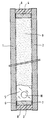
- the drawing is a vertical section view of a fire-resistant glazing according to the invention.
- the glazing comprises two panes of silicate glass 1, 2, each 5 mm thick and each made of thermally toughened float glass.
- glass strips 3, 4, 5 are used, 12 mm wide, for example made of 4 mm thick float glass.
- These glass strips 3, 4, 5 are bonded to the two panes 1, 2 by means of adhesive layers 6, 7 of butyl.
- the groove between the glass strips 3, 4, 5 and the zones located along the edges of the panes 1, 2 is filled with a mass of adhesive sealing material 8 made of polysulphide.
- the intermediate space formed in this way between the two panes 1, 2 is filled with a saline hydrogel 9.
- a hole 10 is made in the strip of glass 5, near its lower end, or cut a corner.
- a hole which serves as an orifice for venting is made in the opposite glass strip, which is not visible in the sectional view.
- these holes which must first be kept free in an appropriate manner, by the introduction, for example, of short sections of tube into the holes, are tightly sealed after the polymerization of the gelling agent and after the removal of the sections of tube used for filling and venting, by placing the adhesive sealing material.
- the bracing frame composed of the glass strips 3, 4, 5
- particular corner pieces such as are used in the bracing frames made of sections of metal profiles, do not are not necessary, since the different glass strips are joined together.
- a closed frame is first made from sections of interlocking sections and brackets and this frame as a whole is placed on one of the two panes
- the glass strips 3, 4, 5 are arranged separately one after the other on one of the two panes, after having been previously coated at least on one edge of a layer butyl adhesive. In this way, the closed bracing frame is first assembled on the glass.
- the fire resistance test in accordance with DIN 4102, part 2, paragraphs 6.1 to 6.2.5 was carried out on fire-resistant glazing designed in this way.
- the test of resistance to fire was made on a fire-resistant glazing in which the spacer, whose width was also 12 mm, was made of a corrosion-resistant steel profile, but the remaining structure of the fire-resistant glazing was identical to the glazing fire barrier according to the invention. While the fire-resistant glazing comprising the bracing frame made of corrosion-resistant steel resisted fire for 25 minutes, the fire-resistant glazing according to the invention resisted fire for 32 minutes and therefore conforms to class. fire resistance F 30.
Landscapes
- Engineering & Computer Science (AREA)
- Civil Engineering (AREA)
- Structural Engineering (AREA)
- Joining Of Glass To Other Materials (AREA)
- Special Wing (AREA)
- Securing Of Glass Panes Or The Like (AREA)
- Insulated Conductors (AREA)
- Laminated Bodies (AREA)
Abstract
Description
- La présente invention concerne un vitrage résistant au feu comprenant deux vitres assemblées hermétiquement à leurs bords par l'intermédiaire d'une entretoise en forme de cadre, l'espace intérieur de ce vitrage étant rempli d'un hydrogel contenant un sel soluble dans l'eau.
- Des vitrages résistant au feu, de cette technique sont connus par exemple par les documents DE-2 713 849 C2, DE-3 530 968 C2, EP-0 001 531 B1 et 0 049 204 B1. Dans le cas de ces vitrages connus résistant au feu, le cadre d'entretoisement est fait de profilés en acier résistant à la corrosion, qui sont assemblés au moyen d'équerres d'emboîtement également en acier résistant à la corrosion.
- L'effet de retardement du feu de tels vitrages en cas d'incendie est basé sur le fait que tout d'abord, des quantités considérables d'énergie provenant de la chaleur dégagée sont absorbées par l'eau et vaporisent l'eau. Après la vaporisation de l'eau, un écran thermique en mousse s'est formé à partir du sel. Pendant la vaporisation de l'eau, la température superficielle du vitrage, du côté opposé à l'action de la chaleur, ne s'élève que de manière insignifiante et reste inférieure à la valeur admissible de 140°K au-dessus de la température initiale suivant la norme DIN 4102. Lorsqu'après la vaporisation de l'eau, l'écran thermique en mousse s'est formé, celui-ci prend alors en charge l'isolation thermique et empêche en particulier le passage du rayonnement thermique à travers le vitrage. Suivant l'épaisseur de la couche de gel, il est possible de fabriquer de cette façon des vitrages coupe-feu, correspondant aux classes de résistance au feu F 30, F 60 ou à des classes supérieures suivant la norme DIN 4102, partie 2.
- Dans le cas de vitrages résistant au feu de cette structure connue, suivant l'épaisseur et le type des vitres utilisées, la couche de gel doit être épaisse d'au moins 15 mm pour remplir les conditions de la classe de résistance au feu F 30. Lors de l'utilisation de deux vitres en verre trempé de 5 mm d'épaisseur chacune par exemple, l'épaisseur du vitrage vaudra de ce fait au moins environ 25 mm.
- Dans de nombreux cas, il est intéressant d'utiliser des vitrages de la technique mentionnée, d'une classe de résistance au feu déterminée, mais présentant une moindre épaisseur totale. Par exemple, une telle exigence peut être due à des raisons de diminution de poids ou à cause d'une structure de cadre déterminée qui limite l'épaisseur du vitrage.
- L'invention a pour but de modifier la structure de ces vitrages résistant au feu connus afin d'accroître davantage l'effet pare-feu. En particulier, on doit obtenir un effet pare-feu aussi performant que celui offert par les vitrages coupe-feu connus avec une épaisseur totale du vitrage inférieure.
- Ce but est atteint, conformément à l'invention, par le fait que le cadre d'entretoisement entre les deux vitres est fait d'un matériau résistant à la chaleur, présentant un coefficient de conductibilité thermique inférieur à 2 kcal/mhK.
- L'invention est basée sur le fait que lors d'essais de tenue au feu effectués sur les vitrages connus, la destruction du vitrage coupe-feu s'amorce en règle générale au bord. Evidemment, l'eau se vaporise plus vite à proximité de l'entretoise métallique que du reste de la surface de vitre. Cela étant, du côté du vitrage éloigné du feu, la zone située le long du bord s'échauffe plus rapidement que la zone centrale et, de la sorte, elle s'affaiblit plus rapidement que le centre de la vitre, ce qui aboutit finalement à la destruction du vitrage depuis sa zone marginale.
- Conformément à l'invention, l'échauffement du vitrage dans la zone marginale est fortement ralenti par l'utilisation d'entretoises présentant un coefficient de conductibilité thermique nettement inférieur à celui de l'acier, et pour une même épaisseur de l'unité de vitrage, le temps de résistance au feu sera nettement accru. De cette façon, il est possible d'atteindre avec une épaisseur nettement inférieure de l'unité de vitrage, la même durée de résistance au feu que les vitrages connus.
- De préférence, pour l'entretoise, on utilise des matières résistant à la chaleur à base de céramique ou de silicate. De telles matières ont un coefficient de conductibilité thermique relativement bas, de l'ordre de 0,5 à 1 kcal/mhK, alors que l'acier résistant à la corrosion présente un coefficient de conductibilité thermique de 15 à 45 kcal/mhK. De plus, ces matières ont l'avantage particulier qu'elles sont insensibles à la solution salée agressive présente dans l'espace intermédiaire du vitrage, de sorte que l'addition de substances anticorrosives particulières, proposée dans le document DE-3 530 968 C2 même en cas d'utilisation de cadres d'entretoisement en acier résistant à la corrosion, est superflue.
- A titre de matières pour les entretoises, des barres, des bandes ou des profilés en verre au silicate, en particulier en verre flotté habituel, se sont avérés particulièrement appropriés. En cas d'utilisation de bandes de verre au silicate, on peut notamment conserver sans modifications le système d'étanchéité habituel comportant un moyen d'étanchéité adhésif interne en butyle, c'est-à-dire un copolymère d'isobutylène et d'isoprène, et un moyen d'étanchéité adhésif externe en thiocol, c'est-à-dire un polymère thermoplastique du groupe des polysulfures d'alcoyle.
- Il est avantageux d'améliorer l'adhérence entre le gel et les entretoises en appliquant sur celles-ci un promoteur d'adhérence. Dans le cas du verre silico-sodo-calcique habituel, les primaires décrits notamment dans le brevet EP-B-0 001 531 conviennent. Dans ce document, on préconise l'utilisation de promoteurs d'adhérence à base de silane susceptible de réagir avec les doubles ou triples liaisons carbonées de l'hydrogel ou à base de titanates ou de zirconates organiques.
- En cas d'utilisation d'une autre matière céramique ou silicatée que le verre flotté habituel, le système adhésif doit, le cas échéant, être adapté à cette matière.
- Un vitrage résistant au feu conçu conformément à l'invention présente, outre les propriétés favorables mentionnées, l'avantage que, grâce à la conduction thermique plus faible dans le cadre d'entretoisement, aucune mesure particulière pour l'isolation thermique ne doit être prise au niveau du châssis du vitrage. Ceci signifie par exemple qu'un montage relativement plus profond du vitrage dans le châssis, c'est-à-dire un recouvrement important dans la zone marginale du vitrage par le châssis, n'est pas nécessaire. Des vitrages résistant au feu conçus conformément à l'invention peuvent donc être installés dans des châssis de construction nettement plus étroite, ce qui confère à la paroi résistant au feu un aspect plus léger.
- En règle générale, les vitrages coupe-feu présentent comme d'autres vitrages une forme rectangulaire, de telle sorte que le cadre d'entretoisement se compose de sections droites. Toutefois, il est évidemment possible de fabriquer des vitrages coupe-feu également dans n'importe quelle autre forme souhaitée. Ainsi, par exemple, lorsque le verre est utilisé comme matériau pour l'entretoise, les bandes de verre peuvent être pliées dans n'importe quelle forme souhaitée après chauffage à leur température de cintrage, et ainsi, par exemple, des vitrages coupe-feu circulaires ou semi-circulaires peuvent être fabriqués.
- D'autres particularités et avantages de l'invention ressortiront des revendications et de la description suivante d'un exemple de réalisation préféré donné avec référence au dessin.
- Le dessin est une vue en coupe verticale d'un vitrage coupe-feu conforme à l'invention.
- Le vitrage comprend deux vitres en verre au silicate 1, 2, épaisses chacune de 5 mm et chacune en verre flotté trempé thermiquement. A titre d'entretoise, entre ces deux vitres 1, 2, on utilise des bandes de verre 3, 4, 5, larges de 12 mm, par exemple en verre flotté épais de 4 mm. Ces bandes de verre 3, 4, 5 sont collées aux deux vitres 1, 2 par l'intermédiaire de couches adhésives 6, 7 de butyle. La rainure entre les bandes de verre 3, 4, 5 et les zones situées le long des bords des vitres 1, 2 est remplie d'une masse de matière d'étanchéité adhésive 8 faite de polysulfure. L'espace intermédiaire formé de cette façon entre les deux vitres 1, 2 est rempli d'un hydrogel salin 9.
- Dans le cas de la fabrication du vitrage coupe-feu, pour pouvoir remplir de liquide gélifiant l'espace intermédiaire dans le double vitrage préparé, on ménage un trou 10 dans la bande de verre 5, à proximité de son extrémité inférieure, ou on en coupe un coin. De même, on ménage dans la bande de verre opposée, qui n'est pas visible sur la vue en coupe, à proximité de son extrémité supérieure un trou qui sert à titre d'orifice de mise à l'atmosphère. Evidemment, ces trous qui dans un premier temps doivent être maintenus libres de manière appropriée, par l'introduction par exemple de courtes sections de tube dans les trous, sont obturés de manière étanche après la polymérisation du gélifiant et après l'enlèvement des sections de tube utilisées pour le remplissage et la mise à l'atmosphère, par la mise en place de la matière d'étanchéité adhésive.
- Dans le cas de l'agencement du cadre d'entretoisement composé des bandes de verre 3, 4, 5, des pièces d'angle particulières, telles qu'elles sont utilisées dans les cadres d'entretoisement faits de sections de profilés métalliques, ne sont pas nécessaires, puisque les différentes bandes de verre sont assemblées l'une à l'autre. Alors que dans le procédé habituel, utilisant des entretoises métalliques, un cadre fermé est d'abord fabriqué à partir de sections de profilés et d'équerres d'emboîtement et ce cadre dans sa globalité est posé sur une des deux vitres, dans le cas du vitrage coupe-feu conforme à l'invention, les bandes de verre 3, 4, 5 sont disposées séparément l'une après l'autre sur une des deux vitres, après avoir été préalablement enduites au moins sur un bord d'une couche adhésive de butyle. De cette façon, le cadre d'entretoisement fermé est d'abord assemblé sur la vitre.
- L'essai de tenue au feu conforme à la norme DIN 4102, partie 2, paragraphes 6.1 à 6.2.5 a été réalisé sur un vitrage coupe-feu conçu de cette façon. De même, l'essai de tenue au feu a été réalisé sur un vitrage coupe-feu dans lequel l'entretoise, dont la largeur valait également 12 mm, était faite d'un profilé en acier résistant à la corrosion, mais la structure restante du vitrage coupe-feu était identique au vitrage coupe-feu conforme à l'invention. Alors que le vitrage coupe-feu comportant le cadre d'entretoisement en acier résistant à la corrosion résistait au feu pendant 25 minutes, le vitrage coupe-feu conforme à l'invention a résisté au feu pendant 32 minutes et est donc conforme à la classe de résistance au feu F 30.
Claims (5)
- Vitrage résistant au feu comprenant au moins deux vitres assemblées hermétiquement à leurs bords par l'intermédiaire d'une entretoise en forme de cadre, l'espace intérieur de ce vitrage étant rempli d'un hydrogel contenant un sel soluble dans l'eau, caractérisé en ce que le cadre d'entretoisement entre les deux vitres (1, 2) est fait d'un matériau résistant à la chaleur, présentant un coefficient de conductibilité thermique inférieur à 2 kcal/mhK.
- Vitrage résistant au feu suivant la revendication 1, caractérisé en ce que le cadre d'entretoisement est fait de barres ou de sections profilées en matériau céramique.
- Vitrage résistant au feu suivant la revendication 1, caractérisé en ce que le cadre d'entretoisement est fait de bandes de verre au silicate (3, 4, 5).
- Vitrage résistant au feu suivant la revendication 3, caractérisé en ce que deux bandes de verre au silicate disposées face à face (5) du cadre d'entretoisement sont pourvues, à proximité de leurs extrémités diagonalement opposées, chacune d'un trou (10) ou d'un coin coupé à titre d'orifice de remplissage et de mise à l'atmosphère.
- Vitrage résistant au feu suivant l'une des revendications précédentes, caractérisé en ce que les surfaces du cadre d'entretoisement en contact avec le gel sont traitées avec un promoteur d'adhérence, notamment, dans le cas d'utilisation de verre au silicate, à base de silane susceptible de réagir avec les doubles ou triples liaisons carbonées de l'hydrogel, ou à base de titanates ou de zirconates organiques.
Applications Claiming Priority (2)
| Application Number | Priority Date | Filing Date | Title |
|---|---|---|---|
| DE19525263A DE19525263A1 (de) | 1995-07-11 | 1995-07-11 | Feuerwiderstandsfähige Verglasung |
| DE19525263 | 1995-07-11 |
Publications (3)
| Publication Number | Publication Date |
|---|---|
| EP0753639A2 true EP0753639A2 (fr) | 1997-01-15 |
| EP0753639A3 EP0753639A3 (fr) | 1998-03-11 |
| EP0753639B1 EP0753639B1 (fr) | 2002-03-13 |
Family
ID=7766557
Family Applications (1)
| Application Number | Title | Priority Date | Filing Date |
|---|---|---|---|
| EP96401475A Expired - Lifetime EP0753639B1 (fr) | 1995-07-11 | 1996-07-04 | Vitrage résistant au feu |
Country Status (8)
| Country | Link |
|---|---|
| US (1) | US5698277A (fr) |
| EP (1) | EP0753639B1 (fr) |
| JP (1) | JPH09118547A (fr) |
| AT (1) | ATE214458T1 (fr) |
| DE (3) | DE19525263A1 (fr) |
| DK (1) | DK0753639T3 (fr) |
| ES (1) | ES2173260T3 (fr) |
| PT (1) | PT753639E (fr) |
Cited By (3)
| Publication number | Priority date | Publication date | Assignee | Title |
|---|---|---|---|---|
| WO2009007452A1 (fr) * | 2007-07-11 | 2009-01-15 | Agc Flat Glass Europe Sa | Vitrage anti-feu |
| EP3254847A1 (fr) | 2016-06-09 | 2017-12-13 | AGC Glass Europe | Vitrage anti-feu |
| EP3254846A1 (fr) | 2016-06-09 | 2017-12-13 | AGC Glass Europe | Vitrage anti-feu |
Families Citing this family (23)
| Publication number | Priority date | Publication date | Assignee | Title |
|---|---|---|---|---|
| DE19922507C2 (de) * | 1999-05-15 | 2003-01-30 | Vetrotech Saint Gobain Int Ag | Brandschutzverglasung |
| DE19951099A1 (de) * | 1999-10-23 | 2001-06-13 | Evobus Gmbh | Fensterscheibe, insbesondere für Fahrzeuge |
| JP4563538B2 (ja) * | 1999-12-28 | 2010-10-13 | 株式会社日本高度医療研究会 | 複層窓 |
| FR2807872B1 (fr) * | 2000-04-17 | 2002-08-30 | Saint Gobain Vitrage | Cadre en verre |
| FR2815374B1 (fr) * | 2000-10-18 | 2003-06-06 | Saint Gobain | Vitrage feuillete et ses moyens d'etancheification peripherique |
| FR2819802B1 (fr) * | 2001-01-24 | 2004-07-23 | Saint Gobain | Structure, notamment pour vitrage thermochrome, comportant une substance contenue entre deux substrats en verre |
| US7090906B2 (en) * | 2001-09-25 | 2006-08-15 | O'keeffe's, Inc. | Fire resistant safety glass |
| EP1431027A1 (fr) * | 2002-12-18 | 2004-06-23 | Scheuten Glasgroep | Agent ignifugéant et sa méthode de production |
| DE20303253U1 (de) | 2003-02-28 | 2003-06-18 | Hero-Glas Veredelungs GmbH, 26906 Dersum | Brandschutzverglasung |
| DK1493556T3 (da) | 2003-07-02 | 2005-12-05 | Scheuten Glasgroep Bv | Fremgangsmåde til fremstilling af brandbeskyttelsesglas |
| GB0327310D0 (en) * | 2003-11-24 | 2003-12-24 | Oztech Pty Ltd | Pressure impulse mitigation |
| RU2258790C1 (ru) * | 2004-01-29 | 2005-08-20 | Панова Лидия Григорьевна | Огнестойкая светопрозрачная конструкция |
| GB2425313B (en) * | 2005-04-20 | 2008-07-30 | Pyroline Services Ltd | Fire resisting composition |
| DE102005027404A1 (de) * | 2005-06-13 | 2006-12-14 | Schröders, Theo | Brandschutzglas und Verfahren zu dessen Herstellung |
| KR101180234B1 (ko) * | 2009-04-03 | 2012-09-05 | (주)엘지하우시스 | 디자인층을 구비한 건물 일체형 태양전지 모듈 |
| GB0906293D0 (en) | 2009-04-14 | 2009-05-20 | Beresford Gary P | Multiple panel glazing unit |
| GB2461773B (en) * | 2009-04-24 | 2010-06-09 | Tuff X Processed Glass Ltd | Insulating glazing |
| CN103527053B (zh) * | 2013-10-30 | 2015-08-12 | 上海交通大学 | 一种高低温环境试验箱的外门门扇 |
| DE102014114241A1 (de) | 2014-09-30 | 2016-03-31 | Hörmann KG Eckelhausen | Vorrichtung und verfahren zur herstellung von brandschutzgläsern |
| DE102015119042A1 (de) | 2015-11-05 | 2017-05-11 | Hörmann KG Eckelhausen | Brandschutzglasfüllvorrichtung, darin verwendbare Entlüftungseinrichtung und Verfahren zum Befüllen von Brandschutzgläsern |
| DE102018120957A1 (de) | 2017-08-29 | 2019-02-28 | Hörmann KG Glastechnik | Verfahren zum Herstellen von Feuerschutzabschlusselementen mit und ohne Verglasung sowie Feuerschutzabschlusselement und Feuerschutzabschlusselementserie |
| CN109914983A (zh) * | 2019-04-30 | 2019-06-21 | 新乡市达威智能门窗实用技术研究中心 | 一种采用内装液体或者低沸点固体的防炸玻璃 |
| US12241305B2 (en) * | 2020-12-10 | 2025-03-04 | The Regents Of The University Of Colorado, A Body Corporate | Insulated assemblies and methods of forming and using same |
Family Cites Families (7)
| Publication number | Priority date | Publication date | Assignee | Title |
|---|---|---|---|---|
| BE782441A (fr) * | 1971-04-30 | 1972-10-23 | Glaverbel | |
| FR2346548A1 (fr) * | 1976-03-30 | 1977-10-28 | Saint Gobain | Vitrage multiple anti-feu, comportant une couche intercalaire de gel |
| FR2405905A1 (fr) * | 1977-10-11 | 1979-05-11 | Saint Gobain | Vitrage pare-feu a gel aqueux |
| DE3037015A1 (de) * | 1980-10-01 | 1982-05-06 | Vereinigte Glaswerke Gmbh, 5100 Aachen | Abstandsrahmen fuer mit einem gel gefuellte feuerwiderstandsfaehige mehrfachglasscheiben |
| DE3530968A1 (de) * | 1985-08-30 | 1987-03-12 | Ver Glaswerke Gmbh | Feuerwiderstandsfaehige verglasung |
| US5106663A (en) * | 1989-03-07 | 1992-04-21 | Tremco Incorporated | Double-paned window system having controlled sealant thickness |
| US5079054A (en) * | 1989-07-03 | 1992-01-07 | Ominiglass Ltd. | Moisture impermeable spacer for a sealed window unit |
-
1995
- 1995-07-11 DE DE19525263A patent/DE19525263A1/de not_active Withdrawn
-
1996
- 1996-05-04 DE DE29608160U patent/DE29608160U1/de not_active Expired - Lifetime
- 1996-07-04 DK DK96401475T patent/DK0753639T3/da active
- 1996-07-04 AT AT96401475T patent/ATE214458T1/de active
- 1996-07-04 DE DE69619737T patent/DE69619737T2/de not_active Expired - Lifetime
- 1996-07-04 PT PT96401475T patent/PT753639E/pt unknown
- 1996-07-04 EP EP96401475A patent/EP0753639B1/fr not_active Expired - Lifetime
- 1996-07-04 ES ES96401475T patent/ES2173260T3/es not_active Expired - Lifetime
- 1996-07-08 JP JP8177881A patent/JPH09118547A/ja active Pending
- 1996-07-10 US US08/678,021 patent/US5698277A/en not_active Expired - Lifetime
Cited By (5)
| Publication number | Priority date | Publication date | Assignee | Title |
|---|---|---|---|---|
| WO2009007452A1 (fr) * | 2007-07-11 | 2009-01-15 | Agc Flat Glass Europe Sa | Vitrage anti-feu |
| EP3254847A1 (fr) | 2016-06-09 | 2017-12-13 | AGC Glass Europe | Vitrage anti-feu |
| EP3254846A1 (fr) | 2016-06-09 | 2017-12-13 | AGC Glass Europe | Vitrage anti-feu |
| WO2017211633A1 (fr) | 2016-06-09 | 2017-12-14 | Agc Glass Europe | Vitrage anti-feu |
| EP3468792B1 (fr) | 2016-06-09 | 2023-08-16 | AGC Glass Europe | Vitrage anti-feu |
Also Published As
| Publication number | Publication date |
|---|---|
| ES2173260T3 (es) | 2002-10-16 |
| EP0753639B1 (fr) | 2002-03-13 |
| PT753639E (pt) | 2002-09-30 |
| ATE214458T1 (de) | 2002-03-15 |
| EP0753639A3 (fr) | 1998-03-11 |
| DE19525263A1 (de) | 1997-03-06 |
| DK0753639T3 (da) | 2002-07-08 |
| JPH09118547A (ja) | 1997-05-06 |
| DE69619737D1 (de) | 2002-04-18 |
| DE29608160U1 (de) | 1996-07-11 |
| US5698277A (en) | 1997-12-16 |
| DE69619737T2 (de) | 2004-03-11 |
Similar Documents
| Publication | Publication Date | Title |
|---|---|---|
| EP0753639B1 (fr) | Vitrage résistant au feu | |
| EP0970930B1 (fr) | Vitrage anti-feu | |
| EP0870893B1 (fr) | Elément vitré à haut pouvoir isolant | |
| EP2633145B1 (fr) | Porte étanche et coupe feu | |
| EP0894935B1 (fr) | Elément vitré isolant | |
| EP0049204B1 (fr) | Cadre entretoise pour vitrage anti-feu à gel | |
| EP0866909B1 (fr) | Fenetre comportant un chassis en bois et un vitrage isolant | |
| BE1008311A5 (fr) | Paroi vitree coupe-feu. | |
| EP3870793B1 (fr) | Procede d'obtention d'un vitrage isolant et vitrage isolant obtenu par le procécé | |
| EP3344838B1 (fr) | Porte de meuble d'enceinte réfrigérée | |
| CA2377460C (fr) | Element plat de protection contre le feu dote d'au moins deux panneaux de verre transparents coupe-feu | |
| FR2508534A1 (fr) | Vitrage isolant pare-feu | |
| EP0079257A1 (fr) | Fenêtre à résistance au feu améliorée, et vitrage en verre pour cette fenêtre | |
| EP0568458B1 (fr) | Elément vitré anti-feu | |
| EP0987397A2 (fr) | Element résistant au feu pour la fermeture d'un local | |
| EP3468792B1 (fr) | Vitrage anti-feu | |
| EP0569298B1 (fr) | Valve pour vitrage isolant anti-feu | |
| EP0823530B1 (fr) | Mur extérieur à effet isolant thermique élevé | |
| FR2602257A1 (fr) | Element de construction coupe-feu | |
| EP0635617B1 (fr) | Panneau transparent pare-flamme | |
| FR2593223A1 (fr) | Chassis pour vitrage antifeu et element vitre resistant au feu | |
| FR2718173A1 (fr) | Profilé porteur stable au feu, par exemple pour verrière et agencement comprenant un tel profilé. | |
| FR2938595A1 (fr) | Systeme d'assemblage de trois corps entre eux pour former une piece sensiblement en forme de "t" et application aux murs-rideaux | |
| FR2754283A1 (fr) | Element de paroi vitree | |
| FR2973823A1 (fr) | Bloc-porte coupe feu |
Legal Events
| Date | Code | Title | Description |
|---|---|---|---|
| PUAI | Public reference made under article 153(3) epc to a published international application that has entered the european phase |
Free format text: ORIGINAL CODE: 0009012 |
|
| AK | Designated contracting states |
Kind code of ref document: A2 Designated state(s): AT BE CH DE DK ES FI FR GB IT LI LU NL PT SE |
|
| PUAL | Search report despatched |
Free format text: ORIGINAL CODE: 0009013 |
|
| AK | Designated contracting states |
Kind code of ref document: A3 Designated state(s): AT BE CH DE DK ES FI FR GB IT LI LU NL PT SE |
|
| 17P | Request for examination filed |
Effective date: 19980803 |
|
| 17Q | First examination report despatched |
Effective date: 20000307 |
|
| GRAG | Despatch of communication of intention to grant |
Free format text: ORIGINAL CODE: EPIDOS AGRA |
|
| RAP1 | Party data changed (applicant data changed or rights of an application transferred) |
Owner name: SAINT-GOBAIN GLASS FRANCE |
|
| GRAG | Despatch of communication of intention to grant |
Free format text: ORIGINAL CODE: EPIDOS AGRA |
|
| GRAH | Despatch of communication of intention to grant a patent |
Free format text: ORIGINAL CODE: EPIDOS IGRA |
|
| GRAH | Despatch of communication of intention to grant a patent |
Free format text: ORIGINAL CODE: EPIDOS IGRA |
|
| REG | Reference to a national code |
Ref country code: GB Ref legal event code: IF02 |
|
| GRAA | (expected) grant |
Free format text: ORIGINAL CODE: 0009210 |
|
| AK | Designated contracting states |
Kind code of ref document: B1 Designated state(s): AT BE CH DE DK ES FI FR GB IT LI LU NL PT SE |
|
| REF | Corresponds to: |
Ref document number: 214458 Country of ref document: AT Date of ref document: 20020315 Kind code of ref document: T |
|
| REG | Reference to a national code |
Ref country code: CH Ref legal event code: EP |
|
| REF | Corresponds to: |
Ref document number: 69619737 Country of ref document: DE Date of ref document: 20020418 |
|
| GBT | Gb: translation of ep patent filed (gb section 77(6)(a)/1977) |
Effective date: 20020521 |
|
| REG | Reference to a national code |
Ref country code: CH Ref legal event code: NV Representative=s name: KIRKER & CIE SA |
|
| REG | Reference to a national code |
Ref country code: DK Ref legal event code: T3 |
|
| REG | Reference to a national code |
Ref country code: PT Ref legal event code: SC4A Free format text: AVAILABILITY OF NATIONAL TRANSLATION Effective date: 20020611 |
|
| REG | Reference to a national code |
Ref country code: ES Ref legal event code: FG2A Ref document number: 2173260 Country of ref document: ES Kind code of ref document: T3 |
|
| PLBE | No opposition filed within time limit |
Free format text: ORIGINAL CODE: 0009261 |
|
| STAA | Information on the status of an ep patent application or granted ep patent |
Free format text: STATUS: NO OPPOSITION FILED WITHIN TIME LIMIT |
|
| 26N | No opposition filed |
Effective date: 20021216 |
|
| RBV | Designated contracting states (corrected) |
Designated state(s): AT BE CH DE DK ES FI FR GB IT LI LU NL PT SE |
|
| PG25 | Lapsed in a contracting state [announced via postgrant information from national office to epo] |
Ref country code: LU Free format text: LAPSE BECAUSE OF NON-PAYMENT OF DUE FEES Effective date: 20140704 |
|
| REG | Reference to a national code |
Ref country code: FR Ref legal event code: PLFP Year of fee payment: 20 |
|
| PGFP | Annual fee paid to national office [announced via postgrant information from national office to epo] |
Ref country code: ES Payment date: 20150611 Year of fee payment: 20 |
|
| PGFP | Annual fee paid to national office [announced via postgrant information from national office to epo] |
Ref country code: LU Payment date: 20150723 Year of fee payment: 20 |
|
| PGFP | Annual fee paid to national office [announced via postgrant information from national office to epo] |
Ref country code: NL Payment date: 20150709 Year of fee payment: 20 |
|
| PGFP | Annual fee paid to national office [announced via postgrant information from national office to epo] |
Ref country code: DE Payment date: 20150630 Year of fee payment: 20 Ref country code: FI Payment date: 20150709 Year of fee payment: 20 Ref country code: CH Payment date: 20150713 Year of fee payment: 20 Ref country code: GB Payment date: 20150701 Year of fee payment: 20 Ref country code: DK Payment date: 20150713 Year of fee payment: 20 Ref country code: PT Payment date: 20150701 Year of fee payment: 20 |
|
| PGFP | Annual fee paid to national office [announced via postgrant information from national office to epo] |
Ref country code: AT Payment date: 20150625 Year of fee payment: 20 Ref country code: FR Payment date: 20150723 Year of fee payment: 20 Ref country code: BE Payment date: 20150731 Year of fee payment: 20 Ref country code: SE Payment date: 20150713 Year of fee payment: 20 |
|
| PGFP | Annual fee paid to national office [announced via postgrant information from national office to epo] |
Ref country code: IT Payment date: 20150727 Year of fee payment: 20 |
|
| REG | Reference to a national code |
Ref country code: DE Ref legal event code: R071 Ref document number: 69619737 Country of ref document: DE |
|
| REG | Reference to a national code |
Ref country code: NL Ref legal event code: MK Effective date: 20160703 |
|
| REG | Reference to a national code |
Ref country code: DK Ref legal event code: EUP Effective date: 20160704 |
|
| REG | Reference to a national code |
Ref country code: CH Ref legal event code: PL |
|
| REG | Reference to a national code |
Ref country code: GB Ref legal event code: PE20 Expiry date: 20160703 |
|
| REG | Reference to a national code |
Ref country code: AT Ref legal event code: MK07 Ref document number: 214458 Country of ref document: AT Kind code of ref document: T Effective date: 20160704 |
|
| REG | Reference to a national code |
Ref country code: ES Ref legal event code: FD2A Effective date: 20161026 |
|
| PG25 | Lapsed in a contracting state [announced via postgrant information from national office to epo] |
Ref country code: GB Free format text: LAPSE BECAUSE OF EXPIRATION OF PROTECTION Effective date: 20160703 |
|
| PG25 | Lapsed in a contracting state [announced via postgrant information from national office to epo] |
Ref country code: PT Free format text: LAPSE BECAUSE OF EXPIRATION OF PROTECTION Effective date: 20160712 |
|
| PG25 | Lapsed in a contracting state [announced via postgrant information from national office to epo] |
Ref country code: ES Free format text: LAPSE BECAUSE OF EXPIRATION OF PROTECTION Effective date: 20160705 |
|
| PG25 | Lapsed in a contracting state [announced via postgrant information from national office to epo] |
Ref country code: LU Free format text: LAPSE BECAUSE OF NON-PAYMENT OF DUE FEES Effective date: 20140704 |
|
| PGRI | Patent reinstated in contracting state [announced from national office to epo] |
Ref country code: LU Effective date: 20150701 |