EP0752811B1 - Bearbeitungsmaschine für reihenkulturen - Google Patents
Bearbeitungsmaschine für reihenkulturen Download PDFInfo
- Publication number
- EP0752811B1 EP0752811B1 EP95914279A EP95914279A EP0752811B1 EP 0752811 B1 EP0752811 B1 EP 0752811B1 EP 95914279 A EP95914279 A EP 95914279A EP 95914279 A EP95914279 A EP 95914279A EP 0752811 B1 EP0752811 B1 EP 0752811B1
- Authority
- EP
- European Patent Office
- Prior art keywords
- shaft
- rotor
- knife
- hoeing
- row
- Prior art date
- Legal status (The legal status is an assumption and is not a legal conclusion. Google has not performed a legal analysis and makes no representation as to the accuracy of the status listed.)
- Expired - Lifetime
Links
Images


Classifications
-
- A—HUMAN NECESSITIES
- A01—AGRICULTURE; FORESTRY; ANIMAL HUSBANDRY; HUNTING; TRAPPING; FISHING
- A01B—SOIL WORKING IN AGRICULTURE OR FORESTRY; PARTS, DETAILS, OR ACCESSORIES OF AGRICULTURAL MACHINES OR IMPLEMENTS, IN GENERAL
- A01B39/00—Machines specially adapted for working soil on which crops are growing
- A01B39/20—Tools; Details
- A01B39/26—Arrangements for protecting plants, e.g. fenders
-
- A—HUMAN NECESSITIES
- A01—AGRICULTURE; FORESTRY; ANIMAL HUSBANDRY; HUNTING; TRAPPING; FISHING
- A01B—SOIL WORKING IN AGRICULTURE OR FORESTRY; PARTS, DETAILS, OR ACCESSORIES OF AGRICULTURAL MACHINES OR IMPLEMENTS, IN GENERAL
- A01B39/00—Machines specially adapted for working soil on which crops are growing
- A01B39/12—Machines specially adapted for working soil on which crops are growing for special purposes, e.g. for special culture
- A01B39/18—Machines specially adapted for working soil on which crops are growing for special purposes, e.g. for special culture for weeding
Definitions
- the invention relates to a processing machine for row crops, for example corn, sugar beets, broad beans, each row at least a sensor detecting the positions of the individual plants in the row and a processing device controlled as a function of the signal from the sensor assigned.
- each row is assigned an ultrasound sensor that detects the positions of the individual plants in the row from above.
- a weeding tool rotating about a vertical axis is pivoted between the individual plants, in order to tear out the weeds present there or to separate them from their roots.
- US-A-3 913 681 discloses a processing machine for row crops, the processing devices (87) depending on a sensor system (H) an approximately horizontally guided one, flat between the plants of the row, in the ground have engaging cleaver (81). The processing is done via a tactile sensor (H) triggered.
- the uniformly driven and rotating Weeding tool (81) is pivoted hydraulically into the row of plants. While the crushing effect of this tool (81) can be seen positively this causes damage, especially to younger plants, so that there is a wide safety area around the plants.
- the invention has for its object a processing machine for To show row cultures of the type described at the beginning, with the base a sensory distinction between crops and weeds either only the individual plants in the row are processed or the entire soil except for a narrow security area around the individual plants is processed.
- the one assigned to each row of the processing machine Processing device is an approximately horizontally guided, between the individual clusters of the row cleaver reaching flat into the ground. This cleaver separates the weeds just below the surface of the soil from their roots. As a rule, the respective weed becomes permanent destroyed, i.e. there is no fear of growing out again. That only flat in the Ground chopping knives also prevent it from being used close to the Crops destruction from close to the surface of the soil Roots of crops.
- An essential and effective way of working the cleaver can be thereby achieve that the cleaver is mounted on a driven rotor and that the cleaver is coaxial with the axis of rotation of the rotor arranged shaft is connected.
- the chopping according to the invention is thereby done in a row achieved that the shaft alternately lockable or on the drive of the rotor can be coupled.
- Hierpei can with a processing device upstream sensor an additional travel sensor and one controlled by its travel signal Delay device for the signal of the sensor may be provided.
- the cleaver against the rotor by means of a Adjustment device is adjustable in its working direction. This will make the Effectiveness of the processing machine is significantly improved because of the Working movement of the cleaver precisely to the driving speed can be coordinated.
- a safety device for the cleaver of the tillage machine to create it is provided that the cleaver opposite the coaxially rotating shaft and / or the rotor limited resilient or elastic is arranged. This can be achieved in that between the shaft and the cleaver is arranged at least one elastic element. So can avoid the cleaver stones or other hard objects. The Cleaver is thus protected against breaking on hard objects that Shocks are not transmitted to the gearbox with full force. That too Transmission is less stressed. It also ensures that the cleaver less worn out.
- the processing machine shown in a plan view in FIG. 1 for plants 1 grown in row crops has a support frame 2.
- the support frame 2 can in turn be mounted on a tractor and / or have its own undercarriage.
- Steering frames 4 which are movable relative to the supporting frame 2 are mounted on the supporting frame 2 transversely to the direction of travel of the processing machine indicated by arrows 3.
- Each steering frame 4 is assigned to a row 5 of plants 1.
- a pivot frame 7 is articulated on each steering frame 4 via parallelogram link 6, which is supported on the floor 9 via a support wheel 8.
- a sensor 10, which detects the individual plants 1, is arranged on the swivel frame 7 near the ground. The sensor 10 is oriented approximately horizontally and transversely to the direction of travel of the processing machine.
- An evaluation and control device 11 is assigned to each of the sensors 10, in which the signal from the sensor is processed.
- the evaluation and control devices control the processing device 12 or 13.
- the processing device 12 has a cleaver 14 and the processing device 13 has a spray nozzle 15 for a chemical agent.
- a mechanical weed control is carried out with the cleaver 14 between the individual plants 1 in a row 5.
- the spray plants 15 spray the individual plants 1 in a row 5 with herbicides.
- the evaluation and control devices take the path signal from with the support wheels 8 connected transducers 16.
- a blow-out opening 17 is assigned to each of them, which surrounds the respective sensor 10 in a ring.
- the sensor 10 is in one Supply line 18 to the blow-out opening 17 is arranged.
- the one from the Blowing opening 17 compressed air flowing out not only blows dirt but also weeds or laterally protruding leaves of the crops from the Detection range of the sensor 10, so that only the more stable approaches of the Useful plants can be detected by the sensor 10.
- the Feed lines 18 can be with the compressor of a tractor or a other compressed air source.
- the evaluation and control devices 11 can also be used to specifically move the steering frame 4 transversely to the direction of travel the processing machine in the direction of the arrows. requirement for this is that the signal of the respective sensor 10 from its distance to the Plant 1 just recorded is dependent. By the of the evaluation and Control devices 11 controlled process of the steering frame 4 in the direction of Arrows can a constant lateral distance of the swing frame 7 to the Plants 1 of the respective row 5 are observed.
- FIG. 2 shows the processing machine according to FIG. 1 in a side view, only the lower swivel frame 7 with the processing device 13 being shown.
- the processing device 13 has a tank 19 and a pump 20 for the pesticide.
- the pump 20 is actuated by the evaluation and control device 11 precisely when the spray nozzle 15 is above a plant 1 previously detected by the sensor 10.
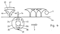
- FIGS. 3 and 4 show the processing device 12 according to FIGS. 1 and 2 in detail.
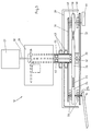
- the cross section according to FIG. 5 shows a motor 27, a coupling 28 and a cover 29, which are each fixedly mounted on the swivel frame 7, not shown here.
- a drive shaft 30 driven by the motor 27 passes through the clutch 28 and is connected in a rotationally fixed manner below the cover 29 to a rotor 31, 32.
- the rotor 31, 32 consists of an upper flywheel 31 and a lower flywheel 32.
- the chopping knife 14 is pivotally mounted on the rotor 31, 32. Bearings 33 are provided for this purpose.
- the chopping knife 14 is connected to a hollow shaft 37 arranged coaxially to the drive shaft 30 by means of a toothed pulley 34 which is fixed relative to it and a toothed belt 35 and a central toothed pulley 36.
- the toothed disks 34 and 36 are between the two flywheels 31 and 32 of the rotor 31, 32 arranged.
- the toothed belt 35 closes one more a second outer toothed disc 38, with which a likewise pivotable on the rotor 31, 32 stored, eccentric counterweight 39 for the cleaver 14 is rotatably connected.
- the bearing of the counterweight 39 on the rotor 31, 32 takes place via bearings 40.
- Between the hollow shaft 7 and the drive shaft 30 are Camp 41 provided.
- a thrust bearing 42 is arranged between the central toothed wheel 36 and the lower one Flywheel 32.
- Other bearings 43 are provided between the hollow shaft 37 and the cover 29.
- the clutch 28 allows two states of the hollow shaft 37. In one state the hollow shaft 37 is determined, and in the other state, the hollow shaft 37 is with the drive shaft 30 rotatably connected. In the first case, the cleaver performs 14 a lateral chopping movement beyond the cover 29. The exit point of the chopping knife 14 depends on the current position the hollow shaft 37. The shape of the chopping movement is determined by the Gear ratio between the toothed disks 36 and 34 and 38 determined.
- the cleaver 14 rotates with the rotor 31, 32 without it To change relative position with respect to the rotor. This relative position depends from the relative position of the hollow shaft 37 to the drive shaft 30.
- the positions of the hollow shaft 37 are chosen so that the cleaver 14 performs a lateral chopping movement, as found in Figure 6 is shown.
- the choice of Relative position between the hollow shaft 37 and the drive shaft 30 in the coupled position of the hollow shaft 37 ensures that the cleaver 14th rotates below the cover 29.
- the arrow 3 indicates the direction of travel of the processing machine according to FIG. 1.
- Line 44 marks the Outer edge of the housing 29.
- An arrow 45 represents the direction of rotation of the rotor 31, 32.
- Arrows 46 to 48 indicate the direction of a curve 49, which is the tip of the Chopping knife 14 performed during the lateral chopping movement.
- the chopping knife 14 only becomes flat during the chopping movement according to curve 49 passed through the bottom 1, d. that is, there is little interference with the ground. This prevents damage to flat roots of plants 1. However, weeds are reliably separated from their roots or torn out. There is no fear of weeds growing back.
- FIG. 5 shows the processing device in perspective.
- the shaft is driven by a power source 27.
- the disk 54 fastened to the hollow shaft 37 rotates.
- the shaft 50 is rotatably mounted in the housing.
- the shaft 50 carries the cleaver 14 on its lower side.
- the disk 55 is arranged on the top in a rotationally fixed manner.
- a toothed belt 56 is wrapped around the disk 55 of the shaft 50 and the disk 54 of the shaft 37.
- the clutch 28 is connected to a control device 51 such that depending on signals from a sensor 10, the clutch 28 through them drive shaft 30 passing therethrough and with the hollow shaft driven thereby 37 and disc 54 is pivoted out of position X0, as indicated by arrows 52a and 52b is indicated.
- the cleaver 14 is in a new position X1 in Reoriented reference to plant location according to angle X1.
- the lead X0-1 of the Cleaver 14 adjusted, e.g. depending on the measured Forward speed of the tractor in the direction of arrow 53.
- one or more can be substituted Drive devices are used, which the drive shaft 30 and the Drive hollow shaft 37 differently and variably, so that e.g. the size of the Toothed washer 34, 36, 38, which are used according to Figure 5, varied as desired will.
- FIG. 6 shows an advantageous fastening of the chopping knife 14 on the shaft 57.
- the shaft 57 is arranged in the housing 29, as shown in FIG.
- the cleaver 14 is screwed onto the fastening sleeve 59 by means of two fastening means designed as screws 58.
- the fastening sleeve 59 is fastened to the shaft 57 by means of the screw 60.
- Elastic sleeves 62 and 63 are arranged between the screw head 61 of the screw 60 and the sleeve 59 on the one hand and the shaft 57 and the sleeve 59 on the other hand.
- the chopping knife 14 is suspended in a resilient and elastically movable manner with respect to the shaft 57.
- the cleaver 14 is due to the elastically buffered suspension of the sleeve 59 limited movement and spring back attached to the shaft 57. Through the Fixing screw 60, the suspension of the knife 14 can be adjusted.
- a self-locking screw 60 is preferably provided. So is over self-locking screw 60 the elasticity of the connection changeable. The Mobility of this connection enables stone protection during operation as well a vertically rocking working movement of the cleaver 14.
- the sleeve 59 can preferably for reasons of weight saving, and so that it has a high smoothness on its surface, from a technical Porcelain or a plastic material can be produced.
- the cleaver 14 can be bent downwards from the fastening point to the processing part be so that the gear is a sufficiently large distance from the ground surface receives.
- a cross-sectional oval shape of the sleeve ensures that the Cleaver 14 can not rotate freely, but only about 5-10 degrees to both Sides can swing out. Thus, it almost does not deviate in normal operation, however depending on the strength of the screw and the elastic connection at Hit with a hard object by about 10-20 degrees. in the Interaction of the pendulum movement generated by the gear and the restricted own movement of the Knife 14 swings the knife tip up and down at the end of each working movement downwards, whereby overlying earth and weed parts are thrown off.
Landscapes
- Life Sciences & Earth Sciences (AREA)
- Engineering & Computer Science (AREA)
- Mechanical Engineering (AREA)
- Soil Sciences (AREA)
- Environmental Sciences (AREA)
- Soil Working Implements (AREA)
- Catching Or Destruction (AREA)
Description
- Figuren 1 und 2
- eine Drauf- und eine Seitenansicht einer zweireihigen Bearbeitungsmaschine,
- Figuren 3 und 4
- zwei Detailansichten einer Bearbeitungsvorrichtung der Bearbeitungsmaschine gemäß den Figuren 1 und 2,
- Figur 5
- eine Detailansicht einer weiteren Bearbeitungsvorrichtung in perspektivischer Darstellung,
- Figur 6
- die elastische oder federnde Anordnung des Hackmessers an der Welle im Schnitt und in Prinzipdarstellung.
Die Auswerte- und Steuereinrichtungen steuern die Bearbeitungsvorrichtung 12 bzw. 13. Dabei weist die Bearbeitungsvorrichtung 12 ein Hackmesser 14 und die Bearbeitungsvorrichtung 13 eine Sprühdüse 15 für einen chemischen Wirkstoff auf. Mit dem Hackmesser 14 erfolgt eine mechanische Unkrautbekämpfung zwischen den einzelnen Pflanzen 1 einer Reihe 5. Mit der Sprühdüse 15 werden die einzelnen Pflanzen 1 einer Reihe 5 mit Herbiziden besprüht.
Claims (7)
- Bearbeitungsmaschine für Reihenkulturen, wie beispielsweise Mais, Zuckerrüben, Ackerbohnen, wobei jeder Reihe mindestens ein die Positionen der einzelnen Pflanzen in der Reihe erfassender Sensor und ein in Abhängigkeit von dem Signal des Sensors gesteuerte Bearbeitungsvorrichtung zugeordnet sind, wobei die Bearbeitungsvorrichtung (12) ein etwa horizontal geführtes, zwischen den einzelnen Pflanzen (1) der Reihe (5) flach in den Boden eingreifendes Hackmesser (14) aufweist,
dadurch gekennzeichnet, daß das Hackmesser (14) an einem permanent angetriebenen Rotor (31,32) gelagert ist und daß das Hackmesser (14) über ein Getriebe mit einer koaxial zu der Drehachse des Rotors angeordneten Welle (37) verbunden ist, die wechselweise feststellbar bzw. an den Antrieb (30) des Rotors ankuppelbar ist, wobei das Hackmesser (14) im festgestellten Zustand der Welle (37) eine seitlich über den Rotor (31,32) hinausgehende Hackbewegung vollführt und im angekuppelten Zustand der Welle (37) vorzugsweise innerhalb des Rotors (31,32) mit diesem umläuft. - Bearbeitungsmaschine nach Anspruch 1, dadurch gekennzeichnet, daß das Hackmesser (14) gegenüber dem Rotor (31, 32) vorzugsweise mittels einer Justiereinrichtung (51) in seiner Arbeitsrichtung einstellbar ist.
- Bearbeitungsmaschine nach Anspruch 1 und 2 dadurch gekennzeichnet, daß das Hackmesser (14) gegenüber der koaxial umlaufenden Welle (37) und/oder dem Rotor (31,32) begrenzt federnd und/oder elastisch angeordnet ist.
- Bearbeitungsmaschine nach Anspruch 3, dadurch gekennzeichnet, daß das Hackmesser (14) an einer Welle (57) befestigt ist, und daß zwischen der Welle (57) und dem Hackmesser (14) zumindest ein elastisches Element (62,63) angeordnet ist.
- Bearbeitungsmaschine nach Anspruch 4, dadurch gekennzeichnet daß das Hackmesser (14) gegenüber der Welle (57) begrenzt federnd und elastisch aufgehängt ist und die Steifigkeit der Befestigung mittels einer Schraube (60) einstellbar ist.
- Bearbeitungsmaschine nach Anspruch 5, dadurch gekennzeichnet daß das Hackmesser (14) während des Arbeitens eine stechende und dabei leicht auf- und abschwingende Arbeitsbewegung (52a) vollführt.
- Bearbeitungsmaschine nach Anspruch 1, dadurch gekennzeichnet daß während des Vorrückens des arbeitenden Hackmessers (14) aus der zentralen Position in die äußere Position zwischen die Pflanzen (1) und bei gleichzeitiger Vorfahrt (53) der Bearbeitungsmaschine (3) die Hackmesserspitze abhängig von der Einstellung der Justiereinrichtung (51) sich näherungsweise auf einer Linie (X0) quer zur Fahrtrichtung bewegt, also der Vorfahrt (53) nacheilt.
Applications Claiming Priority (3)
| Application Number | Priority Date | Filing Date | Title |
|---|---|---|---|
| DE4411080A DE4411080A1 (de) | 1994-03-30 | 1994-03-30 | Bearbeitungsmaschine für Reihenkulturen |
| DE4411080 | 1994-03-30 | ||
| PCT/DE1995/000433 WO1995026622A1 (de) | 1994-03-30 | 1995-03-28 | Bearbeitungsmaschine für reihenkulturen |
Publications (2)
| Publication Number | Publication Date |
|---|---|
| EP0752811A1 EP0752811A1 (de) | 1997-01-15 |
| EP0752811B1 true EP0752811B1 (de) | 1998-08-26 |
Family
ID=6514262
Family Applications (1)
| Application Number | Title | Priority Date | Filing Date |
|---|---|---|---|
| EP95914279A Expired - Lifetime EP0752811B1 (de) | 1994-03-30 | 1995-03-28 | Bearbeitungsmaschine für reihenkulturen |
Country Status (4)
| Country | Link |
|---|---|
| EP (1) | EP0752811B1 (de) |
| AU (1) | AU2134795A (de) |
| DE (2) | DE4411080A1 (de) |
| WO (1) | WO1995026622A1 (de) |
Families Citing this family (8)
| Publication number | Priority date | Publication date | Assignee | Title |
|---|---|---|---|---|
| AT1051U1 (de) * | 1995-10-23 | 1996-10-25 | Haindl Leopold Ing Jun | Auf einem fahrzeug montierte einrichtung zur feststellung der position erntefähiger spargelpflanzen |
| DE19640640A1 (de) * | 1996-02-10 | 1998-02-19 | Andreas Hilker | Verfahren und Vorrichtung zur Exaktsteuerung von Anbaugeräten hinter Zugfahrzeugen |
| DE19648111C2 (de) * | 1996-11-21 | 1998-10-29 | Andreas Hilker | Bearbeitungsmaschine für Reihenkulturen |
| DE19717522C2 (de) * | 1997-04-25 | 2003-08-28 | Andreas Hilker | Aktor für die mechanische Beikrautregulierung innerhalb der Reihen von Reihenkulturpflanzen |
| DE19750130A1 (de) | 1997-11-13 | 1999-05-20 | Amazonen Werke Dreyer H | Bearbeitungseinrichtung zur gezielten Bearbeitung quer zur Reihe |
| WO2005099429A1 (en) * | 2004-04-15 | 2005-10-27 | Radivoj Matic | Automatic rotary electro-pneumatic digger with tractor self-navigation |
| GB0708862D0 (en) * | 2007-05-08 | 2007-06-13 | Univ Copenhagen | Precision weeders |
| NL1041331B1 (nl) * | 2015-06-02 | 2017-01-02 | Sander Johannes Bernaerts Ing | Onkruidverwijderinrichting. |
Family Cites Families (15)
| Publication number | Priority date | Publication date | Assignee | Title |
|---|---|---|---|---|
| US3059704A (en) * | 1960-10-21 | 1962-10-23 | Kasatkin Anatol | Rotary cultivator |
| DE2155182A1 (de) * | 1970-12-16 | 1972-07-06 | Cioni, Paolo, Florenz (Italien) | Motorgetriebene Landmaschine, insbesondere Mähmaschine |
| US3913681A (en) * | 1974-04-17 | 1975-10-21 | Lincoln Farm Equipment Company | Outrigged rotating cultivator |
| IT1125044B (it) * | 1979-03-07 | 1986-05-14 | Barato Paolo | Macchina multipla ad assi verticali per coltura a filari |
| US4768713B1 (en) * | 1982-12-15 | 1995-03-21 | Bert E Roper | Grove sprayer |
| NL8802163A (nl) * | 1988-09-01 | 1990-04-02 | Stichting Inst Mech | Verrijdbare inrichting voor het behandelen van planten zoals gewassen en fruitbomen, en werkwijze voor het gebruiken daarvan. |
| US4989783A (en) * | 1989-08-14 | 1991-02-05 | Fmc Corporation | Sensor mounting |
| DE4004247A1 (de) * | 1990-02-12 | 1991-08-14 | Feser Werner | Servo-geregeltes bearbeitungs-grundgeraet mit elektronischer pflanzenabtastung |
| DE4039797A1 (de) * | 1990-12-13 | 1991-09-26 | Manfred Prof Dr Hoffmann | Sensorgesteuerte pflegetechnik und unkrautregulation |
| US5222324A (en) * | 1991-02-21 | 1993-06-29 | Neall Donald L O | Crop spraying system |
| DK190191A (da) * | 1991-11-21 | 1993-05-22 | Jan Moerk Hansen | Fremgangsmaade samt apparat til rensning af raekker af nytteplanter |
| US5315564A (en) * | 1992-02-06 | 1994-05-24 | Fmc Corporation | Sensing apparatus |
| DE4205231C2 (de) * | 1992-02-21 | 1994-05-19 | Clemens & Co Gmbh | An ein landwirtschaftliches Fahrzeug od.dgl. anbaubare Vorrichtung zur mechanischen Unkrautbeseitigung |
| FR2687532B1 (fr) * | 1992-02-25 | 1998-10-09 | Joseph Martelot | Appareil de binage mecanique inter plants. |
| DE9300093U1 (de) * | 1993-01-07 | 1993-03-18 | Heidtmann, Helmut, 7500 Karlsruhe | Einrichtung zur Bodenbearbeitung |
-
1994
- 1994-03-30 DE DE4411080A patent/DE4411080A1/de not_active Ceased
-
1995
- 1995-03-28 DE DE59503346T patent/DE59503346D1/de not_active Expired - Lifetime
- 1995-03-28 WO PCT/DE1995/000433 patent/WO1995026622A1/de not_active Ceased
- 1995-03-28 EP EP95914279A patent/EP0752811B1/de not_active Expired - Lifetime
- 1995-03-28 AU AU21347/95A patent/AU2134795A/en not_active Abandoned
Also Published As
| Publication number | Publication date |
|---|---|
| DE59503346D1 (de) | 1998-10-01 |
| AU2134795A (en) | 1995-10-23 |
| DE4411080A1 (de) | 1995-10-05 |
| EP0752811A1 (de) | 1997-01-15 |
| WO1995026622A1 (de) | 1995-10-12 |
Similar Documents
| Publication | Publication Date | Title |
|---|---|---|
| AT520294B1 (de) | Hackvorrichtung | |
| EP0407896B1 (de) | Bodenbearbeitungsmaschine für Reihenkulturen | |
| EP0426960B1 (de) | Hackvorrichtung für ein Bodenbearbeitungsgerät | |
| EP3387890A1 (de) | Reiheneinheit zur mechanischen unkrautbekämpfung, landwirtschaftliche maschine mit wenigstens zwei derartigen reiheneinheiten sowie verfahren zur mechanischen unkrautbekämpfung | |
| EP3016494B1 (de) | Landwirtschaftliches gerät und verfahren zur bearbeitung von pflanzenstoppeln | |
| EP3804484A1 (de) | Vorrichtung zur reb- und zeilenkulturpflanzenpflege und maschine zum betreiben der vorrichtung | |
| DE102009047181B4 (de) | Landwirtschaftliches Bodenbearbeitungsgerät zur Befestigung an einem Fahrzeug | |
| DE60013240T2 (de) | Mehrzweckmaschine zum Zwischenkultivieren für Baum- oder Strauchpflanzungen bzw. Wein- oder Obstgärten | |
| LU503190B1 (de) | Bodenbearbeitungsgerät | |
| DE3830141C1 (en) | Method and apparatus for working the growth between the rows of young standing maize plants in maize-cultivation areas | |
| EP0752811B1 (de) | Bearbeitungsmaschine für reihenkulturen | |
| EP3977837B1 (de) | Bodenbearbeitungsvorrichtung, verfahren zur bodenbearbeitung in einer reihe einer reihenkultur und landwirtschaftliche bodenbearbeitungsmaschine | |
| DE102015004212A1 (de) | Walzeneinheit für ein landwirtschaftliches Arbeitsgerät zur Maisstoppelbearbeitung | |
| DE102017108119A1 (de) | Reiheneinheit zur mechanischen Unkrautbekämpfung, landwirtschaftliche Maschine mit zumindest zwei derartiger Reiheneinheiten und Verfahren zur mechanischen Unkrautbekämpfung | |
| DE10153964A1 (de) | Bodenbearbeitungsgerät zum Einebnen, Zerkleinern und Rückverfestigen des Bodens | |
| DE4428288C2 (de) | Landwirtschaftliches Arbeitsgerät, insbesondere Mulchgerät | |
| DE527579C (de) | Bodenbearbeitungsmaschine mit umlaufenden Werkzeugen | |
| EP4250902B1 (de) | Beikrautregulierungsmaschine | |
| DE3640399C1 (en) | Single-row or multi-row crust breaker for the comminution of encrusted soil layers above seedlings in sugar-beet cultivation | |
| DE4302198C2 (de) | Verfahren und Gerät zur Unkrautbekämpfung bei Kulturpflanzen, insbesondere Mais | |
| EP4537644B1 (de) | Bodenbearbeitungsgerät | |
| DE69523590T2 (de) | Kultivator | |
| DE19648111C2 (de) | Bearbeitungsmaschine für Reihenkulturen | |
| DE102009006045A1 (de) | Mulch- und/oder Mähmaschine | |
| DE2242033A1 (de) | Verfahren zur bearbeitung von landwirtschaftlichem boden o.dgl. und vorrichtung zur durchfuehrung des verfahrens |
Legal Events
| Date | Code | Title | Description |
|---|---|---|---|
| PUAI | Public reference made under article 153(3) epc to a published international application that has entered the european phase |
Free format text: ORIGINAL CODE: 0009012 |
|
| 17P | Request for examination filed |
Effective date: 19960926 |
|
| AK | Designated contracting states |
Kind code of ref document: A1 Designated state(s): DE FR GB NL |
|
| 17Q | First examination report despatched |
Effective date: 19970321 |
|
| GRAG | Despatch of communication of intention to grant |
Free format text: ORIGINAL CODE: EPIDOS AGRA |
|
| GRAG | Despatch of communication of intention to grant |
Free format text: ORIGINAL CODE: EPIDOS AGRA |
|
| GRAH | Despatch of communication of intention to grant a patent |
Free format text: ORIGINAL CODE: EPIDOS IGRA |
|
| GRAH | Despatch of communication of intention to grant a patent |
Free format text: ORIGINAL CODE: EPIDOS IGRA |
|
| GRAA | (expected) grant |
Free format text: ORIGINAL CODE: 0009210 |
|
| AK | Designated contracting states |
Kind code of ref document: B1 Designated state(s): DE FR GB NL |
|
| REF | Corresponds to: |
Ref document number: 59503346 Country of ref document: DE Date of ref document: 19981001 |
|
| GBT | Gb: translation of ep patent filed (gb section 77(6)(a)/1977) |
Effective date: 19981027 |
|
| ET | Fr: translation filed | ||
| PGFP | Annual fee paid to national office [announced via postgrant information from national office to epo] |
Ref country code: GB Payment date: 19990315 Year of fee payment: 5 |
|
| PGFP | Annual fee paid to national office [announced via postgrant information from national office to epo] |
Ref country code: NL Payment date: 19990329 Year of fee payment: 5 |
|
| PLBE | No opposition filed within time limit |
Free format text: ORIGINAL CODE: 0009261 |
|
| STAA | Information on the status of an ep patent application or granted ep patent |
Free format text: STATUS: NO OPPOSITION FILED WITHIN TIME LIMIT |
|
| 26N | No opposition filed | ||
| PGFP | Annual fee paid to national office [announced via postgrant information from national office to epo] |
Ref country code: FR Payment date: 20000314 Year of fee payment: 6 |
|
| PG25 | Lapsed in a contracting state [announced via postgrant information from national office to epo] |
Ref country code: GB Free format text: LAPSE BECAUSE OF NON-PAYMENT OF DUE FEES Effective date: 20000328 |
|
| PG25 | Lapsed in a contracting state [announced via postgrant information from national office to epo] |
Ref country code: NL Free format text: LAPSE BECAUSE OF NON-PAYMENT OF DUE FEES Effective date: 20001001 |
|
| GBPC | Gb: european patent ceased through non-payment of renewal fee |
Effective date: 20000328 |
|
| NLV4 | Nl: lapsed or anulled due to non-payment of the annual fee |
Effective date: 20001001 |
|
| PGFP | Annual fee paid to national office [announced via postgrant information from national office to epo] |
Ref country code: DE Payment date: 20010418 Year of fee payment: 7 |
|
| PG25 | Lapsed in a contracting state [announced via postgrant information from national office to epo] |
Ref country code: FR Free format text: LAPSE BECAUSE OF NON-PAYMENT OF DUE FEES Effective date: 20011130 |
|
| REG | Reference to a national code |
Ref country code: FR Ref legal event code: ST |
|
| PG25 | Lapsed in a contracting state [announced via postgrant information from national office to epo] |
Ref country code: DE Free format text: LAPSE BECAUSE OF THE APPLICANT RENOUNCES Effective date: 20030703 |
|
| PGRI | Patent reinstated in contracting state [announced from national office to epo] |
Ref country code: DE Effective date: 20021002 |