EP0751248A1 - Strick- und Umhängeschlossteil für Flachstrickmaschine - Google Patents
Strick- und Umhängeschlossteil für Flachstrickmaschine Download PDFInfo
- Publication number
- EP0751248A1 EP0751248A1 EP96304755A EP96304755A EP0751248A1 EP 0751248 A1 EP0751248 A1 EP 0751248A1 EP 96304755 A EP96304755 A EP 96304755A EP 96304755 A EP96304755 A EP 96304755A EP 0751248 A1 EP0751248 A1 EP 0751248A1
- Authority
- EP
- European Patent Office
- Prior art keywords
- needle
- cam
- loop
- butt
- raising cam
- Prior art date
- Legal status (The legal status is an assumption and is not a legal conclusion. Google has not performed a legal analysis and makes no representation as to the accuracy of the status listed.)
- Granted
Links
- 238000009940 knitting Methods 0.000 title claims abstract description 80
- 230000009191 jumping Effects 0.000 claims description 3
- 239000004744 fabric Substances 0.000 description 5
- 230000015572 biosynthetic process Effects 0.000 description 3
- 238000000034 method Methods 0.000 description 2
- 230000000630 rising effect Effects 0.000 description 2
- 150000001875 compounds Chemical class 0.000 description 1
- 238000010276 construction Methods 0.000 description 1
Images

Classifications
-
- D—TEXTILES; PAPER
- D04—BRAIDING; LACE-MAKING; KNITTING; TRIMMINGS; NON-WOVEN FABRICS
- D04B—KNITTING
- D04B15/00—Details of, or auxiliary devices incorporated in, weft knitting machines, restricted to machines of this kind
- D04B15/32—Cam systems or assemblies for operating knitting instruments
- D04B15/36—Cam systems or assemblies for operating knitting instruments for flat-bed knitting machines
- D04B15/362—Cam systems or assemblies for operating knitting instruments for flat-bed knitting machines with two needle beds in V-formation
- D04B15/365—Cam systems or assemblies for operating knitting instruments for flat-bed knitting machines with two needle beds in V-formation with provision for loop transfer from one needle bed to the other
Definitions
- This invention relates to a knitting cam for controlling back and forth movement of a compound needle having a single butt for back and forth movement of the needle, and more particularly relates to a knitting and transfer cam for a flat knitting machine which also performs transfer of a loop.
- a knitting and transfer cam for a flat knitting machine for moving needles upwardly and downwardly between a knit position, a tuck position and a welt position in order to knit a knitted fabric and for operating the needles so as to transfer loops is known for example from Japanese Laid-Open Patent Application No. Heisei 4-2847.
- a transfer raising cam for further raising a needle on the delivery side in transfer is provided, so that a needle on the delivery side is raised to a higher position than that adopted upon ordinary knitting.
- a loop receiving side cam for raising a needle on the loop receiving side in transfer at such a timing that the needle on the loop receiving side is inserted into a loop of a knitted fabric which is raised to its highest position at the timing at which the needle on the delivery side is raised to its highest position and is held at a shoulder portion provided on the shank of the needle on the loop delivery side is provided in a central recessed portion of the needle raising cam.
- butt travel loci which extend along the cams are suitable changed over to perform ordinary knitting or transfer of loops.
- the changing over between the butt travelling loci is normally performed by suitable projection towards or retraction from an operative position of a cam located at a predetermined position.
- a plurality of movable cams are required for the changing over for ordinary knitting or for transfer of loops, and this means that the lock is complicated due to the arrangement of the movable cams.
- a knitting and transfer cam for a flat knitting machine, wherein, at a location above a needle raising cam having a loop receiving needle raising cam in the inside thereof, a loop delivering needle raising cam having a raising cam face continuous with a raising cam face of the needle raising cam is mounted for movement into and out of an operative position, and a loop receiving needle lowering cam face having a loop receiving needle butt lowering locus continuous with a needle butt raising locus of the loop receiving needle raising cam is formed along a lower edge of the loop delivering needle raising cam.
- the loop receiving needle raising cam provided in a recessed portion in the inside of the needle raising cam may comprise a fixed cam and a rockable cam.
- a needle raising cam top element which faces a concave portion provided at the centre of the needle raising cam, an inclined face continuous with the recessed portion is provided, and the needle raising cam top element is formed as a half height element while a loop delivering raising cam is formed with full height such that a loop receiving needle butt which has been raised along a loop receiving needle raising locus extending along the loop receiving needle raising cam passes the needle raising cam top element and is engaged by the loop receiving needle lowering cam face on the lower edge of the loop delivering needle raising cam so as to be introduced into the loop receiving needle butt lowering locus.
- the loop delivering needle raising cam is retracted to its inoperative position while the needle raising cam top element is formed as a cam which can raise a needle to its highest position so that a needle to form a loop is first raised to its highest position by the needle raising cam and the needle raising cam top element and is then lowered by the knitting cam while it receives, in the hook thereof, a yarn supply and draws out the supplied yarn through an old loop to form a new loop.
- a higher density tuck stitch which has a smaller loop length than the tuck stitch described above is knitted in the following manner.
- the presser acts, when a butt having passed the top portion of the needle raising cam comes to the knitting cam, to push the butt into a corresponding needle groove so that the butt jumps the lowering cam face of the knitting cam without engaging with the same.
- the butt is then engaged by the lowering cam face of the fixed cam located in the inside of the knitting cam so that it is lowered by the lowering cam face of the fixed cam. Since the most lowered position of the butt then is higher than the most lowered position by the knitting cam, a new loop thus produced is a higher density loop which is smaller than a loop formed by the knitting cam.
- Transfer of a loop is performed in the following manner. Transfer of a loop is performed with the loop delivering needle raising cam positioned in its operative position. A needle on the loop delivery side is raised to its highest position, and the hook in an open condition of a receiving side needle is inserted into a loop held at a stepped portion of the needle at which a blade is provided. Thereafter, the loop delivery side needle and then the receiving side needle are lowered, whereupon the delivery side needle moves out of the loop while the loop is received in the hook of the receiving side needle, thereby completing transfer of the loop.
- the butt of the loop receiving side needle jumps the needle raising cam and is raised to a position around its tuck position by the loop receiving needle raising fixed cam and the rockable cam in the needle raising cam.
- the loop receiving side needle inserts its hook into the blade of the loop delivery side needle to thus insert the hook into the loop held at the stepped portion of the loop delivery side needle.
- the loop receiving side needle is lowered a little by the loop receiving needle lower cam face provided on the lower edge of the transfer raising cam, whereafter the needle butt is pushed in by an action of the presser.
- the loop delivery side needle continues to be lowered until it comes to the lowermost position of the knitting cam delivering its loop to the hook of the loop receiving side needle.
- the needle butt is first lowered by the loop receiving needle lowering cam face on the lower face of the loop delivering needle raising cam and then jumps, by an action of the presser, the raising cam face of the needle raising cam and the lowering cam face of the knitting cam and moves generally horizontally in the recessed portion in the inner face of the knitting cam.
- a loop is held in the hooks of both of the needles on the loop delivery side and the loop receiving side. Then, the two needles are both lowered to the same height positions as those upon starting along the fixed cam faces.
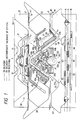
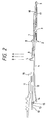
- a carriage in which a cam 1 of the present invention is incorporated is shown as viewed from the lower face side in Figs. 1 and 3, and a side elevation of a needle 2 and so forth operated by a cam lock of the carriage is shown in Fig. 2.
- the cam 1 of the present invention is provided for use with a needle 2 of the one-butt type.
- the needle 2 is of the type wherein a needle jack 4 is engaged with a needle body 3, and a single needle butt 5 is provided on the needle jack 4.
- a slider 7 is inserted on an upper edge of an end of the needle body 3 for fitting sliding movement in a channel-shaped portion of the needle jack 4 so that, when a slider butt 8 is operated, a hook 9 of the needle body 3 can be opened or closed by a forward end portion of the slider 7.
- a head portion of a select jack 10 is engaged with an upper portion of a tail portion of the needle jack 4, while a head portion of a selector 11 is engaged with the select jack 10.
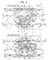
- a needle raising cam top element 28 of gate shape and of half height is positioned between the inclined faces 26a and 26b, and has a pair of triangular raising cam faces 28a and 28b at a top portion thereof and has an inclined face 28d formed along a bottom edge thereof and defining a recessed portion 28c therein.
- the needle raising cam 23 is formed from a single part including the needle raising cam top element 28.
- some extension must be left at a flat portion of the needle raising cam top element 28 at the extremity of the inclined face 28d, and to this end the width of the top portion in a horizontal direction to be jumped upon knitting of a tuck stitch is greater than that of a conventional raising cam.
- a pair of downwardly inclined faces 30a and 30b inclined towards the centre are provided parallel to the direction of movement of the carriage on the inner sides of central portions of the raising cam faces 23a and 23b of the needle raising cam 23 respectively, and a loop receiving side needle raising cam 32 is provided between the inclined faces 30a and 30b.
- the loop receiving side needle raising cam 32 is composed of a loop receiving side needle raising fixed cam 33 of a mountain shape having a pair of raising cam faces 33a and 33b on the opposite side thereof, and a loop receiving side needle raising rockable cam 34 having a pair of cam faces 34a and 34b of a mountain shape and supported for rocking motion around a pivot 35.
- the loop receiving side needle raising rockable cam 34 is provided in an overlapping condition with the loop receiving side needle raising fixed cam 33 in a concave portion 31 continuous with the inclined faces 30a and 30b.
- the loop receiving side needle raising rockable cam 34 has a top portion projecting as a triangular shape from the top portion of the loop receiving side needle raising fixed cam 33 until it is positioned within the recessed portion 28c of the needle raising cam top element 28 such that, when the loop receiving side needle raising rockable cam 34 is rocked to the right in Fig.
- the raising cam face 34a is aligned with the raising cam face 33a of the needle raising cam 23, but when the loop receiving side needle raising rockable cam 34 is locked to the left, the raising cam face 34b is aligned with the raising cam face 33b of the needle raising cam 23.
- the top portion of the rockable cam 34 extends fully from the base plate 22 similarly to the needle raising cam 23.
- a loop delivering needle raising cam 40 is provided at a location above the needle raising cam top element 28.
- the loop delivering needle raising cam 40 has a mountain shape having a pair of raising cam faces 40a and 40b on the left and right sides thereof and has a concave portion 40c formed along a lower edge thereof such that it accepts a top portion of the needle raising cam top element 28 therein.
- the loop delivering needle raising cam 40 has a pair of half thickness portions 40f and 40g having lowering cam faces 40d and 40e on the left and right sides of the concave portion 40c respectively.
- the loop delivering needle raising cam 40 is supported such that it is projected to or retracted from a full position in a vertical direction by suitable means.
- a pair of shoulder portions 44a and 44b are formed along a lower side of the cam 40 such that the width of the lower side of the cam 40 is a little narrower than the width of the top portion of the needle raising cam 23, but the raising cam face 23a of the needle raising cam 23 and the raising cam face 40a of the loop delivering needle raising cam 40 are continuous with each other.
- a guard cam 46 is provided in such a position that it surrounds a top portion of the loop delivering needle raising cam 40 with a butt path 45 left therebetween.
- a pair of knitting cams 49 and 50 having lowering cam faces 47 and 48 opposed to the raising cam faces 23a and 23b of the needle raising cam 23 are mounted for upward and downward movement with butt paths 51 and 52 left therebetween. Since the knitting cams 49 and 50 have a symmetrical structure to each other, only the knitting cam 50 will be described.
- a slider guide cam 58 for engaging with the slider butt 8 to operate the slider 7 for the needle 2 is provided at the centre of the lock 21 above the guard cam 46.
- each cam denoted at H is a cam of half height
- each cam denoted at F is a cam of full height.
- the presser 63 sinks a needle jack butt corresponding to a needle butt which is to jump the needle raising cam top element 28 as described hereinabove, since the jumping width is great as described above, the presser 63 also has a great length so as to cover the extent of the width. Consequently, the opposite ends of the presser 63 must be arranged in an overlapping relationship with the end portions of the pressers 62 and 64 positioned on each side of the presser 63 and are thus arranged as in the embodiment.
- the needle butt 5 having been raised along the cam face 23a then moves horizontally relative to the carriage remaining at the position of the shoulder 44a of the needle raising cam 23, whereafter it is raised to its highest position by the needle raising cam top element 28. Then, the needle receives a yarn supply from a yarn feed (not shown), and then as the carriage moves further, the needle butt 5 is engaged with and lowered by a lowering cam face 46b of the guard cam 46. Thereafter, the needle butt 5 is lowered to its lowermost position by the lowering cam face 48 while forming a needle loop from the supplied yarn. The needle butt 5 having been lowered to its lower end position is then raised to the height of the original position by a guide cam 66.
- the select jack butt 16 corresponding to each needle to perform knitting of a tuck stitch is positioned to the H position by an action of the selector 11. Then, the presser 63 at the H position is positioned to its operative position while the other pressers 62 and 64 at the H position are positioned to their respective inoperative positions.
- the needle butt 5 of the needle 2 corresponding to the select jack 10 is pushed in the corresponding needle groove, and consequently the needle butt 5 is not engaged by the needle raising cam top element 28 and accordingly moves horizontally succeeding the shoulder portion 44a without being raised along the raising cam face 28a of the needle raising cam top element 28.
- the needle 2 receives in the hook 9 thereof a new yarn supply with a previous loop or loops held therein.
- the needle butt 5 is engaged by and lowered by the lowering cam face 48 of the knitting cam 50 so that it thereafter follows the locus H' shown by a double-short, single-long line, in a similar way to the knitting of a knit stitch.
- the slider 7 follows the locus H' shown by a double-short, single-long line in which the slider butt 8 is moved upwardly and downwardly by the slider guide cam 58 to open and close the hook 9 of the needle 2.
- a higher density tuck stitch wherein the size of a knitted loop is comparatively small is formed in the following manner.
- the lowermost position is higher than the position to which the needle butt 5 is lowered otherwise by the lowering cam face 48 of the knitting cam 50. Consequently, a loop formed by the needle 2 is smaller in size than a loop which is formed by an action of the knitting cam 50, and accordingly, the loop formed is a loop of a higher density tuck stitch.
- Such stitch is used, for example, for the knitting of a boundary portion of an intarsia knitted fabric and so forth.
- the needle butt 5 lowered to the lowermost position by the guide cam 56 enters, as the carriage advances, into the ordinary tuck locus indicated by a double-short, single-long line.
- the loop delivering needle raising cam 40 is projected fully to its operative position. Then, a loop is transferred from a needle on one of the two beds raised by the loop delivering needle raising cam 40 on the carriage to another needle on the other bed raised by the loop receiving side needle raising cam 32 on the carriage.
- front and rear carriages F and B move in the direction indicated by the arrow from the right to the left in Fig. 4.
- a loop delivering select jack butt is selected to the A position while a loop receiving select jack butt is selected to the H position.
- the needle butts 5 are raised, without being acted upon by the pressers 60 and 61, to the uppermost positions along the raising cam face 23b of the needle raising cam 23 and the raising cam face 40b of the loop delivering needle raising cam 40 and then are lowered along the lowering cam faces 46a and 47 of the quard cam 46 and the knitting cam 49, whereafter they are guided to the original height positions by a guide cam 67, respectively, as indicated by single-short, single long lines in Fig. 4 The loci are denoted at A' in Fig. 4.
- the slider butt 8 advances straightforwardly relative to the carriage B as indicated by A" also after passing the A position. Consequently, the slider 7 assumes a lower position with respect to the needle body 3, and consequently the hook 9 is put into an open condition. Keeping this condition, the loop delivery side needle butt 5 is raised along the raising cam face 23b of the needle raising cam 23.
- a loop which has been held in the hook leaves the hook and is stopped by a stepped portion 18 in the proximity of a blade 17 in a condition wherein it surrounds the spring. Thereafter, the needle 2 is continuously raised to its highest position along the loop delivering needle raising cam 40 (the B position in Fig. 4).
- the loop receiving side needle butt After passing the D point, the loop receiving side needle butt is raised by the inclined face 28d of the needle raising cam top element 28 of half height, passes the needle raising cam top element 28 and is then engaged by the lowering cam face 40e on the lower edge of the loop delivering needle raising cam 40 (the E position in Fig. 4). Thereafter, the loop receiving side needle butt is lowered along the lowering cam face 40e until it enters the inclined face 26b (the F position in Fig. 4).
- the needle butt 5 having entered the inclined face 26b rides over the inclined face 26b and is disengaged from the needle raising cam 23 as the carriages advance. Thereupon, the select jack butt 16 is pushed by the presser 64 again. Consequently, the needle butt 5 jumps the raising cam face 23b of the needle raising cam 23 and the lowering cam face 48 of the knitting cam 50 and enters the concave portion 53, in which it moves horizontally relative to the carriage, keeping its height until it is engaged by the lowering inclined face of the extension 55 of the guide cam 56 (the G position in Fig. 4). Meanwhile, the loop delivery side needle has been lowered to the receiving side needle by the lowering cam face 46a of the guard cam 46 while closing the hook thereof to start the escape therefrom of the loop to be transferred.
- the loop delivery side needle butt 5 having been lowered along the lowering cam face 46a of the guard cam 46 is further lowered by the lowering cam face 47 of the knitting cam 49, whereupon the needle escapes from the loop which has been held thereon so that the loop remains on the hook of the receiving side needle (the G position in Fig. 4).
- the loop receiving needle is lowered by the lowering cam face 57 of the extension 55 of the guide cam 56.
- the slider butt of the loop receiving side needle is lowered a little by the slider guide cam 58, since the amount of the lowering movement of the needle by the needle butt is larger, the hook is closed after it receives the loop, and the needle receiving side needle returns to its original height with the hook closed.
- the travel locus of a loop receiving side needle is the same as that upon transfer of a loop.
- the travel loci of the needle butt and of the slider butt on the loop delivery side are denoted by H' and H" respectively.
- the loop delivering needle passes the top portion of the loop delivering needle raising cam 40 and is lowered along the lowering cam face 46a of the guard cam 46. Then, when the needle butt 5 comes to the position (the F position of Fig. 4) at the lowermost portion of the cam face 46a, the presser 62 acts to push in the needle butt 5 so that the needle butt 5 thereafter moves horizontally relative to the carriage B.
- the hook of the loop delivery side needle cannot escape from a loop which has been held thereon, and while the loop remains held on the hook of the loop delivering needle, it is held also on the hook of the receiving side needle. Then, the needle butt 5 jumps the lowering cam face 47 of the knitting cam 49 so that it is guided into the recess in the knitting cam 49, whereafter it is lowered by a lowering cam face 68a of a fixed cam 68. During the operation, in the locus after passing the E point, the loop is held on the hooks of both the delivery side and the receiving side.
- the cam lock of the present invention is constructed such that only a loop delivering needle raising cam for transfer selection is formed as a movable cam mounted for movement into and out of an operative position so that a loop delivering needle is raised and a loop receiving needle is lowered by the cam, occurrence of trouble such as a failure in changing over in cam control which arises from use of a plurality of movable cams is eliminated and the cam lock can withstand use for a long period of time.
Landscapes
- Engineering & Computer Science (AREA)
- Textile Engineering (AREA)
- Knitting Machines (AREA)
Applications Claiming Priority (3)
| Application Number | Priority Date | Filing Date | Title |
|---|---|---|---|
| JP187849/95 | 1995-06-30 | ||
| JP18784995 | 1995-06-30 | ||
| JP18784995A JP3465174B2 (ja) | 1995-06-30 | 1995-06-30 | 横編機におけるニット,トランスファー兼用カム |
Publications (2)
| Publication Number | Publication Date |
|---|---|
| EP0751248A1 true EP0751248A1 (de) | 1997-01-02 |
| EP0751248B1 EP0751248B1 (de) | 1999-09-29 |
Family
ID=16213300
Family Applications (1)
| Application Number | Title | Priority Date | Filing Date |
|---|---|---|---|
| EP19960304755 Expired - Lifetime EP0751248B1 (de) | 1995-06-30 | 1996-06-27 | Strick- und Umhängeschlossteil für Flachstrickmaschine |
Country Status (5)
| Country | Link |
|---|---|
| EP (1) | EP0751248B1 (de) |
| JP (1) | JP3465174B2 (de) |
| DE (1) | DE69604453T2 (de) |
| ES (1) | ES2138291T3 (de) |
| TW (1) | TW306508U (de) |
Cited By (12)
| Publication number | Priority date | Publication date | Assignee | Title |
|---|---|---|---|---|
| US7269975B2 (en) | 2003-10-10 | 2007-09-18 | Shima Seiki Manufacturing Limited | Cam apparatus for knitting fabric |
| CN101029429B (zh) * | 2006-02-28 | 2011-01-05 | 株式会社岛精机制作所 | 横机的编织用三角装置 |
| CN102321945A (zh) * | 2011-08-25 | 2012-01-18 | 浙江海润精工机械有限公司 | 电脑针织横机编织三角 |
| CN102383255A (zh) * | 2011-09-29 | 2012-03-21 | 陶春明 | 一种电脑横机的三角编织系统 |
| CN102383256A (zh) * | 2011-09-29 | 2012-03-21 | 陶春明 | 一种电脑横机的中山三角 |
| CN102517779A (zh) * | 2011-12-21 | 2012-06-27 | 陶春明 | 一种电脑针织横机的中山三角 |
| CN102517781A (zh) * | 2011-12-21 | 2012-06-27 | 陶春明 | 一种电脑横机的中山三角 |
| CN102605536A (zh) * | 2011-01-21 | 2012-07-25 | 黄岩新前华鑫针织机械厂 | 多功能电脑横机三角系统 |
| CN102995285A (zh) * | 2011-09-13 | 2013-03-27 | 株式会社岛精机制作所 | 具备复合针的横编机以及横编机的导针片控制方法 |
| CN103088535A (zh) * | 2013-01-11 | 2013-05-08 | 邓福明 | 一种电脑横机三针道及双向移圈技术的编制控制机构 |
| CN103334220A (zh) * | 2013-03-31 | 2013-10-02 | 浙江金优科技有限公司 | 在同一行内编织、集圈的单系统电脑横机及针织方法 |
| CN104233616A (zh) * | 2014-09-02 | 2014-12-24 | 江苏国茂纺织科技有限公司 | 电脑针织横编机的编织机构 |
Families Citing this family (2)
| Publication number | Priority date | Publication date | Assignee | Title |
|---|---|---|---|---|
| CN102605538A (zh) * | 2012-03-30 | 2012-07-25 | 冯加林 | 一种横机电磁选针三角编织机构 |
| CN102828336A (zh) * | 2012-10-02 | 2012-12-19 | 宁波慈星股份有限公司 | 针织横机中的多功能三角 |
Citations (4)
| Publication number | Priority date | Publication date | Assignee | Title |
|---|---|---|---|---|
| GB2164363A (en) * | 1984-09-13 | 1986-03-19 | Stoll & Co H | A combined knitting/transfer cam system for flat-bed knitting machines |
| US4637227A (en) * | 1985-07-19 | 1987-01-20 | Shima Idea Center Co., Ltd. | Flat knitting machine having compound needles |
| GB2177427A (en) * | 1985-07-04 | 1987-01-21 | Schieber Universal Maschf | Flat knitting machine |
| EP0535985A1 (de) * | 1991-10-04 | 1993-04-07 | Shima Seiki Mfg., Ltd. | Verfahren zum Überhängen von Maschen und Vorrichtung zum Überhängen von Maschen an einer Flachstrickmaschine |
-
1995
- 1995-06-30 JP JP18784995A patent/JP3465174B2/ja not_active Expired - Fee Related
-
1996
- 1996-06-18 TW TW085219374U patent/TW306508U/zh unknown
- 1996-06-27 DE DE1996604453 patent/DE69604453T2/de not_active Expired - Lifetime
- 1996-06-27 EP EP19960304755 patent/EP0751248B1/de not_active Expired - Lifetime
- 1996-06-27 ES ES96304755T patent/ES2138291T3/es not_active Expired - Lifetime
Patent Citations (4)
| Publication number | Priority date | Publication date | Assignee | Title |
|---|---|---|---|---|
| GB2164363A (en) * | 1984-09-13 | 1986-03-19 | Stoll & Co H | A combined knitting/transfer cam system for flat-bed knitting machines |
| GB2177427A (en) * | 1985-07-04 | 1987-01-21 | Schieber Universal Maschf | Flat knitting machine |
| US4637227A (en) * | 1985-07-19 | 1987-01-20 | Shima Idea Center Co., Ltd. | Flat knitting machine having compound needles |
| EP0535985A1 (de) * | 1991-10-04 | 1993-04-07 | Shima Seiki Mfg., Ltd. | Verfahren zum Überhängen von Maschen und Vorrichtung zum Überhängen von Maschen an einer Flachstrickmaschine |
Cited By (16)
| Publication number | Priority date | Publication date | Assignee | Title |
|---|---|---|---|---|
| US7269975B2 (en) | 2003-10-10 | 2007-09-18 | Shima Seiki Manufacturing Limited | Cam apparatus for knitting fabric |
| CN101029429B (zh) * | 2006-02-28 | 2011-01-05 | 株式会社岛精机制作所 | 横机的编织用三角装置 |
| CN102605536A (zh) * | 2011-01-21 | 2012-07-25 | 黄岩新前华鑫针织机械厂 | 多功能电脑横机三角系统 |
| CN102605536B (zh) * | 2011-01-21 | 2013-11-27 | 孙立华 | 多功能电脑横机三角系统 |
| CN102321945A (zh) * | 2011-08-25 | 2012-01-18 | 浙江海润精工机械有限公司 | 电脑针织横机编织三角 |
| CN102995285B (zh) * | 2011-09-13 | 2014-07-09 | 株式会社岛精机制作所 | 具备复合针的横编机以及横编机的导针片控制方法 |
| CN102995285A (zh) * | 2011-09-13 | 2013-03-27 | 株式会社岛精机制作所 | 具备复合针的横编机以及横编机的导针片控制方法 |
| CN102383256A (zh) * | 2011-09-29 | 2012-03-21 | 陶春明 | 一种电脑横机的中山三角 |
| CN102383255A (zh) * | 2011-09-29 | 2012-03-21 | 陶春明 | 一种电脑横机的三角编织系统 |
| CN102517781A (zh) * | 2011-12-21 | 2012-06-27 | 陶春明 | 一种电脑横机的中山三角 |
| CN102517779A (zh) * | 2011-12-21 | 2012-06-27 | 陶春明 | 一种电脑针织横机的中山三角 |
| CN103088535A (zh) * | 2013-01-11 | 2013-05-08 | 邓福明 | 一种电脑横机三针道及双向移圈技术的编制控制机构 |
| CN103334220A (zh) * | 2013-03-31 | 2013-10-02 | 浙江金优科技有限公司 | 在同一行内编织、集圈的单系统电脑横机及针织方法 |
| CN103334220B (zh) * | 2013-03-31 | 2015-03-04 | 浙江金越管业有限公司 | 在同一行内编织、集圈的单系统电脑横机及针织方法 |
| CN104233616A (zh) * | 2014-09-02 | 2014-12-24 | 江苏国茂纺织科技有限公司 | 电脑针织横编机的编织机构 |
| CN104233616B (zh) * | 2014-09-02 | 2016-05-18 | 江苏国茂纺织科技有限公司 | 电脑针织横编机的编织机构 |
Also Published As
| Publication number | Publication date |
|---|---|
| DE69604453T2 (de) | 2000-05-31 |
| JPH0921039A (ja) | 1997-01-21 |
| TW306508U (en) | 1997-05-21 |
| ES2138291T3 (es) | 2000-01-01 |
| EP0751248B1 (de) | 1999-09-29 |
| JP3465174B2 (ja) | 2003-11-10 |
| DE69604453D1 (de) | 1999-11-04 |
Similar Documents
| Publication | Publication Date | Title |
|---|---|---|
| US6125661A (en) | Flat knitting machine | |
| EP0751248B1 (de) | Strick- und Umhängeschlossteil für Flachstrickmaschine | |
| EP0897027B1 (de) | Flachstrickmaschine mit bewegbaren, schlaufeformenden Platinen | |
| EP0602622B1 (de) | Platinenvorrichtung für Flachstrickmaschinen | |
| US5367892A (en) | Stitch increasing for flat knitting machines | |
| JP3085657B2 (ja) | 横編機 | |
| EP0959162A2 (de) | Vorrichtung zum Halten einer Maschenschlaufe für eine Flachstrickmaschine | |
| US6018966A (en) | Stitch forming method and a flat knitting machine therefor | |
| JP7483257B2 (ja) | 丸編機におけるジャカード編地編成機構、その編成機構を用いた編成方法及びその編成機構で用いられるシンカー | |
| EP2025785B1 (de) | Strickverfahren für intarsienmusterware und flachstrickmaschine | |
| JP6807451B2 (ja) | 横編機でのプレーティング編成方法 | |
| JP2604677B2 (ja) | 横編機におけるトランスファージャック | |
| JP3408735B2 (ja) | トランスファージャック目移し機構を備えた横編機 | |
| EP0698679B1 (de) | Strickschlussteil und Schluss | |
| KR100768347B1 (ko) | 코이동 기구를 구비하는 횡편기 및 코이동 방법 | |
| US5239843A (en) | Knitting machine for the production of plush goods | |
| JPH0874146A (ja) | コンパウンドニードルを用いた横編機における経糸用カムロック | |
| JPH0684583B2 (ja) | 増目方法及び増目機能を有する横編機用操針カム | |
| US5163305A (en) | Knitting machine with stitch retention sinkers | |
| US4333320A (en) | Left-left flat knitting machine | |
| EP4306698A1 (de) | Verfahren zum stricken von durch eine flachstrickmaschine hergestellten maschenketten-gestricken | |
| KR102697548B1 (ko) | 환편기 구조 | |
| JP2604657B2 (ja) | 横編機における目移し時の編針制御装置 | |
| JP2530242B2 (ja) | 増目機能を有する横編機用操針カム | |
| US2902846A (en) | Knitting machines |
Legal Events
| Date | Code | Title | Description |
|---|---|---|---|
| PUAI | Public reference made under article 153(3) epc to a published international application that has entered the european phase |
Free format text: ORIGINAL CODE: 0009012 |
|
| AK | Designated contracting states |
Kind code of ref document: A1 Designated state(s): DE ES FR GB IT |
|
| RTI1 | Title (correction) | ||
| 17P | Request for examination filed |
Effective date: 19970107 |
|
| GRAG | Despatch of communication of intention to grant |
Free format text: ORIGINAL CODE: EPIDOS AGRA |
|
| 17Q | First examination report despatched |
Effective date: 19981221 |
|
| GRAG | Despatch of communication of intention to grant |
Free format text: ORIGINAL CODE: EPIDOS AGRA |
|
| GRAH | Despatch of communication of intention to grant a patent |
Free format text: ORIGINAL CODE: EPIDOS IGRA |
|
| GRAH | Despatch of communication of intention to grant a patent |
Free format text: ORIGINAL CODE: EPIDOS IGRA |
|
| GRAA | (expected) grant |
Free format text: ORIGINAL CODE: 0009210 |
|
| AK | Designated contracting states |
Kind code of ref document: B1 Designated state(s): DE ES FR GB IT |
|
| REF | Corresponds to: |
Ref document number: 69604453 Country of ref document: DE Date of ref document: 19991104 |
|
| ITF | It: translation for a ep patent filed | ||
| REG | Reference to a national code |
Ref country code: ES Ref legal event code: FG2A Ref document number: 2138291 Country of ref document: ES Kind code of ref document: T3 |
|
| ET | Fr: translation filed | ||
| PLBE | No opposition filed within time limit |
Free format text: ORIGINAL CODE: 0009261 |
|
| STAA | Information on the status of an ep patent application or granted ep patent |
Free format text: STATUS: NO OPPOSITION FILED WITHIN TIME LIMIT |
|
| 26N | No opposition filed | ||
| REG | Reference to a national code |
Ref country code: GB Ref legal event code: IF02 |
|
| PGFP | Annual fee paid to national office [announced via postgrant information from national office to epo] |
Ref country code: FR Payment date: 20100709 Year of fee payment: 15 |
|
| PGFP | Annual fee paid to national office [announced via postgrant information from national office to epo] |
Ref country code: ES Payment date: 20100713 Year of fee payment: 15 |
|
| PGFP | Annual fee paid to national office [announced via postgrant information from national office to epo] |
Ref country code: GB Payment date: 20100623 Year of fee payment: 15 |
|
| GBPC | Gb: european patent ceased through non-payment of renewal fee |
Effective date: 20110627 |
|
| REG | Reference to a national code |
Ref country code: FR Ref legal event code: ST Effective date: 20120229 |
|
| PG25 | Lapsed in a contracting state [announced via postgrant information from national office to epo] |
Ref country code: FR Free format text: LAPSE BECAUSE OF NON-PAYMENT OF DUE FEES Effective date: 20110630 |
|
| PG25 | Lapsed in a contracting state [announced via postgrant information from national office to epo] |
Ref country code: GB Free format text: LAPSE BECAUSE OF NON-PAYMENT OF DUE FEES Effective date: 20110627 |
|
| REG | Reference to a national code |
Ref country code: ES Ref legal event code: FD2A Effective date: 20130531 |
|
| PG25 | Lapsed in a contracting state [announced via postgrant information from national office to epo] |
Ref country code: ES Free format text: LAPSE BECAUSE OF NON-PAYMENT OF DUE FEES Effective date: 20110628 |
|
| PGFP | Annual fee paid to national office [announced via postgrant information from national office to epo] |
Ref country code: IT Payment date: 20140620 Year of fee payment: 19 Ref country code: DE Payment date: 20140625 Year of fee payment: 19 |
|
| REG | Reference to a national code |
Ref country code: DE Ref legal event code: R082 Ref document number: 69604453 Country of ref document: DE Representative=s name: WEICKMANN & WEICKMANN PATENTANWAELTE - RECHTSA, DE Ref country code: DE Ref legal event code: R082 Ref document number: 69604453 Country of ref document: DE Representative=s name: PATENTANWAELTE WEICKMANN & WEICKMANN, DE |
|
| REG | Reference to a national code |
Ref country code: DE Ref legal event code: R119 Ref document number: 69604453 Country of ref document: DE |
|
| PG25 | Lapsed in a contracting state [announced via postgrant information from national office to epo] |
Ref country code: IT Free format text: LAPSE BECAUSE OF NON-PAYMENT OF DUE FEES Effective date: 20150627 |
|
| PG25 | Lapsed in a contracting state [announced via postgrant information from national office to epo] |
Ref country code: DE Free format text: LAPSE BECAUSE OF NON-PAYMENT OF DUE FEES Effective date: 20160101 |