EP0749336B1 - Kanüle zum subkutanen ablegen eines elementes - Google Patents
Kanüle zum subkutanen ablegen eines elementes Download PDFInfo
- Publication number
- EP0749336B1 EP0749336B1 EP95910530A EP95910530A EP0749336B1 EP 0749336 B1 EP0749336 B1 EP 0749336B1 EP 95910530 A EP95910530 A EP 95910530A EP 95910530 A EP95910530 A EP 95910530A EP 0749336 B1 EP0749336 B1 EP 0749336B1
- Authority
- EP
- European Patent Office
- Prior art keywords
- cannula
- handle
- sleeve
- holder
- lever
- Prior art date
- Legal status (The legal status is an assumption and is not a legal conclusion. Google has not performed a legal analysis and makes no representation as to the accuracy of the status listed.)
- Expired - Lifetime
Links
Images


Classifications
-
- A—HUMAN NECESSITIES
- A61—MEDICAL OR VETERINARY SCIENCE; HYGIENE
- A61M—DEVICES FOR INTRODUCING MEDIA INTO, OR ONTO, THE BODY; DEVICES FOR TRANSDUCING BODY MEDIA OR FOR TAKING MEDIA FROM THE BODY; DEVICES FOR PRODUCING OR ENDING SLEEP OR STUPOR
- A61M37/00—Other apparatus for introducing media into the body; Percutany, i.e. introducing medicines into the body by diffusion through the skin
-
- A—HUMAN NECESSITIES
- A61—MEDICAL OR VETERINARY SCIENCE; HYGIENE
- A61M—DEVICES FOR INTRODUCING MEDIA INTO, OR ONTO, THE BODY; DEVICES FOR TRANSDUCING BODY MEDIA OR FOR TAKING MEDIA FROM THE BODY; DEVICES FOR PRODUCING OR ENDING SLEEP OR STUPOR
- A61M37/00—Other apparatus for introducing media into the body; Percutany, i.e. introducing medicines into the body by diffusion through the skin
- A61M37/0069—Devices for implanting pellets, e.g. markers or solid medicaments
Definitions
- the invention relates to a cannula for depositing an element in a The body of a living being, comprising a first handle Cannula holder and an axially surrounding it at least in some areas Slidable sleeve having a stylet extending in the cannula second handle, whereby the element like long-term medicinal product, identification carrier or a capsule containing a radioactive substance by relative movement between the stylet and the cannula receiving the element.
- a corresponding cannula can be found in WO 92/15362.
- the Position fixation in particular by a cannula tip side of the cannula Closure at least in some areas in the form of a medical Active substance containing ointment-like material, an adhesive material or Silicone plug.
- Additional cannulas for placing solid or semi-solid preparations under the skin of a living being are, for example, US 4,900,304, US 4,950,234 or EP 0 255 123 A2.
- EP 0 304 107 A1 describes an injection cannula for placing an implant described, the cannula itself is intended for single use.
- an implant is in a cannula for transport purposes alone fixed in position, by a stylet and distally by a pen. So that the pen cannot slip out of the cannula in an uncontrolled manner, the outside of a protective cover.
- a flexible cannula is used to identify animals intended; whose distal area has a smaller cross-section than that, in which a stylet can be moved.
- the object of the present invention is to develop a cannula of the type mentioned in such a way that on the one hand a problem-free and flawless fixation of the position of the element to be implanted is possible without the need for foreign substances which can penetrate into the body during implantation, in which the element is implanted. It should also be possible to check the position of the element in a simple manner, even if the cannula consists of non-translucent material and in particular of metal. On the other hand, there should be the possibility of inserting the cannula into the body and then placing the element down by pulling the cannula back with one hand.
- the task is solved by that when pressing the second handle starting from the sleeve, the sleeve with the Cannula holder by at least one of this spreading element or one of the outgoing locking or lever element can be locked to the cannula holder or the sleeve.
- the cannula holder is an immovable
- the cannula surrounding approach and a surrounding and relative to this axially displaceable comprises the first handle having sleeve body that of the Approach at least one penetrating the sleeve body when pressure is applied to the second Handle extends against a section of the sleeve supporting spreading element and that when moving the first handle in the direction of the second handle the Sleeve body brings the expansion element into engagement with the section and the approach pulls along.
- the locking element is preferably an angle lever, the short leg in Area of the second handle, preferably along the outside of the cannula faces away surface and its long leg with its free end on the Cannula can be supported on the side facing away from the first handle.
- the angle lever can be moved from the second handle and Pivot axis for the angle lever-forming receptacle can be clamped.
- the short one Leg with its free end region to be supported on the second handle and spaced between the receptacle and the support to the second handle run.
- the short leg can with a section, preferably with its free end can be snapped onto the second handle, thereby ensuring is that an uncontrolled swiveling back of the angle lever cannot take place.
- the lever element can preferably be a hinge such as a film hinge be connected to the first handle.
- a handle such as a projection starts from the lever element and which is then detected when the element is no longer to be in engagement with the sleeve.
- the lever element preferably extends tangentially in the sleeve — also a radial one Course is possible - with the handle running in this area of the lever element and protrudes over the sleeve.
- the lever element itself can be locked in the sleeve with an end projection be, preferably with the cannula holder locked to the sleeve, the end Projection penetrates the sleeve and engages in a recess in the cannula holder.
- the lever element is preferably material-related in the direction of the sleeve spring-loaded, which automatically locks between the needle holder and the sleeve takes place when the cannula is inserted, there is alternatively the possibility that the lever element in the absence of force on this spaced from the sleeve runs, so that the locking must be controlled.
- the at least externally compliant properties of a portion of the cannula is clamped in which the cannula is compared to a cross-section between the element and the cannula tip deviating cross-section or an opening.
- the Cross-sectional reduction formed by an at least partially peripheral bead will. But also other ways to change the cross-section Grain of a cannula wall section or by forming an opening possible. A compression of the cannula to achieve the change in cross-section through which the element to be implanted is also clamped.
- the position of the Elementes by placing the cannula in the area where the element is in front of it Implantation to be fixed in position, undergoes a cross-sectional change. Since that too implanting element at least on the outside resilient or elastic properties has, a secure clamping is possible without the risk of damage of the element takes place, in particular when medical or radioactive preparations are included.
- a cannula (10) used.
- the cannula (10) can be a steel cannula, a plastic cannula or around a cannula of other suitable material, preferably with a bevel Act tip (12).
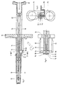
- the cannula (10) is held by a cannula holder (14) added, which in the exemplary embodiment in a handle such as handles (16) transforms.
- a sleeve (18) extends in front of and behind the handles (16) is slotted away from the cannula to one in the longitudinal direction of the cannula (10) shifting and also provided on the outside with a handle (20)
- Mandrin (24) is connected, via which this is not shown in Fig. 1 and in Fig. 2 enlarged element (26) by relative displacement between The stylet and cannula (10) can be placed in one body.
- the element (26) deposited by withdrawing the cannula (10) can of course also a deposit by moving the stylet (24) in the direction of Cannula tip (12).
- the cannula (10) is also surrounded by a protective cap (17) on the Cannula holder (14) is attached.
- the cannula (10) has a between the handle (16) and the cannula tip (12) Geometry change such as lumen constriction (28) on in different ways can be manufactured.
- the cannula wall can be grained or at least with one be provided in some areas surrounding bead. In particular, it is provided that for example, grit two diametrically spaced openings (28) and (30) are produced, the inner edges (32) and (34) of which are in the interior of the Extend cannula (10), i.e. the desired changes in geometry or cross-section cause.
- the cannula (10) is now the element to be implanted (26) clamped. This requires that the element has flexible or elastic properties at least on the outside, to ensure that the element itself is not damaged, for example by Preparations or radioactive substances in an envelope are not uncontrolled can escape.
- the openings offer (28) and (30) at the same time the possibility of an optical inspection of the clamped element (26), so have the function of viewing windows.
- the Openings (28), (30) can also push the element in, so that a Position is fixed. In this case there are no additional changes in lumen required.
- the cannula attachment (38) can have spreading elements (40), the free ends (44) of which extend in the direction of the handle (16) and resiliently in the direction of the sleeve (18) are protruding, the free end (44) when pressure is exerted on the handle (20) of the expansion element (40) to a section like paragraph (46) of the inner wall of the Sleeve (18) abuts.
- the expansion elements (40) move immovably from one of the cannulas (10) surrounding cannula attachment (38), which is surrounded by a sleeve body (48), the the handle (16).
- the cannula attachment (38) and the sleeve body (48) form the cannula holder (14), wherein the expansion element (40) then a perforation (42) of the sleeve body (48) can enforce when the free end (44) of the expansion element (40) on the shoulder (46) the sleeve (18) should abut.
- the handle (16) is mentioned axially withdrawn, whereby the sleeve body (48) first along the Cannula hub (38) moves before an annular projection (50) of the sleeve body (48) abuts a step (52) of the cannula attachment (38) and this at a further axial Movement of the cannula holder (14) pulls along.
- FIGS. 4 to 9 Other ways of locking between the sleeve (18) and the cannula holder (14) result from FIGS. 4 to 9.
- the Cannula holder (14) with its section displaceable within the sleeve (18) must be formed in several parts, that is, no sections that can be moved relative to one another includes as is the case with the embodiment of FIGS. 1 and 2.
- the handle (20) of the Ejection piston (22) having sleeve (18) from an angle lever (54) on the Handle (16) of the cannula holder (14) can be supported, so that when pressure is applied the handle (20) in the direction of the cannula tip (12) the sleeve (18) with the Cannula holder (14) are axially displaceable as a unit.
- the angle lever (54) can be pivoted about an axis (56) which is supported by a receptacle (57) is formed, in which the angle lever (54) can be latched.
- the recording (57) starts from the grip (20) of the sleeve (18).
- the short leg (58) of the angle lever (54) extends along the Cannula tip (12) facing away from the surface (60) of the handle (20) and runs to this spaced in areas.
- the short leg (58) has a preferably bead-like End portion (62), which can then snap into the handle (20) when the Angle lever (54) is to be unlocked in the manner described below.
- the angle lever (54) over, for example, its short Lock leg (58) such that an uncontrolled pivoting of the Angle lever (54) is excluded.
- the locking according to the embodiment of FIGS. 7 to 9 takes place via a lever (68), which starts from the handle (16) of the cannula holder (14) and with a End section (70) in the form of an extending in the direction of the cannula (10) Projection in an adapted recess (72) of the sleeve (18) tangentially or radially can intervene. Then the section (70) can preferably completely the sleeve (18) enforce and engage in a recess (74) of the cannula holder (14) to the Reinforce locking, especially if the wall of the sleeve (18) is thin is.
- the lever element (68) is preferably connected to the via a kind of film hinge (76) Handle (16) connected and spring biased towards the sleeve due to the material.
- the projection (70) shows the endeavor to always lie against the sleeve (18).
- the handle (16) lever elements (80), (82) extending diametrically to one another, but not are biased towards the sleeve (18). Rather, they run with their in Direction of the sleeve (18) extending end portions (84), (86) spaced from Outer surface of the sleeve. If you want to lock the lever (80), (82) in Pressure is exerted on the sleeve (18) so that the projections (84), (86) in corresponding recesses (88), (90) or (92), (94) of the sleeve (18) or the Insert the cannula holder (14).
Landscapes
- Health & Medical Sciences (AREA)
- Engineering & Computer Science (AREA)
- General Health & Medical Sciences (AREA)
- Public Health (AREA)
- Anesthesiology (AREA)
- Biomedical Technology (AREA)
- Heart & Thoracic Surgery (AREA)
- Hematology (AREA)
- Life Sciences & Earth Sciences (AREA)
- Animal Behavior & Ethology (AREA)
- Dermatology (AREA)
- Medical Informatics (AREA)
- Veterinary Medicine (AREA)
- Infusion, Injection, And Reservoir Apparatuses (AREA)
- Media Introduction/Drainage Providing Device (AREA)
- Materials For Medical Uses (AREA)
- Surgical Instruments (AREA)
- External Artificial Organs (AREA)
- Prostheses (AREA)
- Measurement Of The Respiration, Hearing Ability, Form, And Blood Characteristics Of Living Organisms (AREA)
Description
Andererseits soll die Möglichkeit bestehen, das Einstechen der Kanüle in den Körper und das anschließende Ablegen des Elements durch Zurückziehen der Kanüle mit einer Hand durchführen zu können.
- Fig. 1
- einen Schnitt durch eine Kanüle zum Implantieren eines Elementes wie medizinischen Präparats oder Identifikationsträgers,
- Fig. 2
- einen Ausschnitt aus der Kanüle nach Fig. 1, jedoch in vergrößerter Darstellung,
- Fig. 3
- einen weiteren Ausschnitt der Kanüle nach Fig 1,
- Fig. 4
- einen Längsschnitt durch eine weitere Ausführungsform einer Kanüle,
- Fig. 5
- einen Ausschnitt der Kanüle nach Fig. 4, jedoch um 90° gedreht,
- Fig. 6
- einen Schnitt entlang der Linie AB in Fig. 5,
- Fig. 7
- eine dritte Ausführungsform einer Kanüle,
- Fig. 8
- einen Schnitt entlang der Linie in Richtung der Linie CD in Fig. 7 und
- Fig. 9
- eine alternative Lösung einer Arretierung zu dem der Fig. 7 zu entnehmenden Vorschlag.
Claims (19)
- Kanüle (10), bestimmt zum Ablegen eines Elements (26) in einem Körper eines Lebewesens, umfassend einen eine erste Handhabe (16) aufweisenden Kanülenhalter (14) und eine diesen zumindest bereichsweise umgebende und zu diesem axial verschiebbare, einen sich in der Kanüle erstreckenden Mandrin (24) aufweisende Hülse (18) mit zweiter Handhabe (20), wobei das Element durch Relativbewegung zwischen dem Mandrin und der das Element aufnehmenden Kanüle (10) in dem Körper ablegbar ist,
dadurch gekennzeichnet,
daß bei Druck auf die zweite von der Hülse (18) ausgehende Handhabe (20) die Hülse mit dem Kanülenhalter (14) durch zumindest ein von diesem ausgehendes Spreizelement (40) oder ein von dem Kanülenhalter oder der Hülse ausgehendes Rast- oder Hebelelement (54, 68, 80, 82) verrastbar ist. - Kanüle nach Anspruch 1,
dadurch gekennzeichnet,
daß der Kanülenhalter (14) aus einem unverrückbar die Kanüle (10) umgebenden Kanülenansatz (38) und einem diesen umgebenden und relativ zu diesem axial verschiebbaren die erste Handhabe (16) aufweisenden Hülsenkörper (48) besteht, daß von dem Kanülenansatz zumindest ein von der Kanülenspitze (12) weg in Richtung der Hülse (18) sich erstreckendes Spreizelement (40) ausgeht, welches sich bei Druck auf die zweite Handhabe gegen einen Abschnitt (46) der Hülse abstützt, und daß bei Bewegung der von dem Kanülenhalter (14) ausgehenden ersten Handhabe in Richtung der zweiten Handhabe der Hülsenkörper das Spreizelement in Ausgriff mit dem Abschnitt bringt und sodann den Ansatz mitzieht. - Kanüle nach Anspruch 1,
dadurch gekennzeichnet,
daß von der Hülse (18) ein verschwenkbares Rastelement wie Hebel (54) ausgeht, das gegen den Kanülenhalter (14) bzw. dessen Handhabe (16) abstützbar ist. - Kanüle nach Anspruch 3,
dadurch gekennzeichnet,
daß das Rastelement ein Winkelhebel (54) ist, dessen kurzer Schenkel (58) im Bereich der zweiten Handhabe, vorzugsweise entlang deren äußerer der Kanüle (10) abgewandten Fläche (60) verläuft. - Kanüle nach zumindest einem der vorhergehenden Ansprüche,
dadurch gekennzeichnet,
daß der Winkelhebel (56) in einer von der zweiten Handhabe (20) ausgehenden, Schwenkachse (56) für den Winkelhebel bildenden Aufnahme (57) festklemmbar ist. - Kanüle nach zumindest einem der vorhergehenden Ansprüche,
dadurch gekennzeichnet,
daß der kurze Schenkel (58) des Winkelhebels (54) in seinem freien Endbereich (62) an der zweiten Handhabe (20) abgestützt und/oder verrastbar ist und zwischen Abstützung bzw. Verrastung und der Schwenkachse (56) beabstandet zu der Außenfläche (60) der zweiten Handhabe (20) verläuft. - Kanüle nach zumindest Anspruch 1,
dadurch gekennzeichnet,
daß von dem Kanülenhalter (14) ein außenseitig entlang der Hülse (18) verlaufender und mit dieser verrastbares Hebelelement (68, 80, 82) ausgeht. - Kanüle nach zumindest Anspruch 7,
dadurch gekennzeichnet,
daß das Hebelelement (68) vorzugsweise über ein Scharnier wie Filmscharnier (76) mit der ersten Handhabe (16) verbunden ist und über eine radial oder seitlich zur Hülse (18) verlaufende Handhabe (78) erfaßbar und verschwenkbar ist. - Kanüle nach zumindest einem der vorhergehenden Ansprüche,
dadurch gekennzeichnet,
daß das Hebelelement (68) mit einem endseitigen Vorsprung (70) in der Hülse (18) arretierbar ist. - Kanüle nach zumindest einem der vorhergehenden Ansprüche,
dadurch gekennzeichnet,
daß bei der zu der Hülse (18) arretierten Kanülenhalterung (14) der endseitige Vorsprung (70) des Hebelelements (68) die Hülse (18) durchsetzt und in eine Aussparung (74) der Kanülenhalterung eingreift. - Kanüle nach zumindest einem der vorhergehenden Ansprüche,
dadurch gekennzeichnet,
daß das Hebelelement (68) in Richtung der Hülse (18) vorzugsweise werkstoffbedingt federvorgespannt ist. - Kanüle nach zumindest einem der vorhergehenden Ansprüche,
dadurch gekennzeichnet,
daß das Hebelelement (80, 82) bei fehlender Krafteinwirkung auf dieses beabstandet zur Hülse (18) verläuft. - Kanüle nach zumindest einem der vorhergehenden Ansprüche,
dadurch gekennzeichnet,
daß zwei Hebelelement (80, 82) von der ersten Handhabe (16) ausgehen. - Kanüle nach vorzugsweise einem der vorhergehenden Ansprüche,
dadurch gekennzeichnet,
daß das zumindest außenseitig nachgiebige Eigenschaften aufweisende Element (26) von einem Abschnitt (36) der Kanüle (10) festgeklemmt ist, in dem die Kanüle im Vergleich von zwischen dem Element und der Kanülenspitze (12) vorhandenen Querschnitt einen abweichenden Querschnitt oder eine Durchbrechung (28, 30) aufweist. - Kanüle nach Anspruch 14,
dadurch gekennzeichnet,
daß die Querschnitts- bzw. Lumenänderung durch eine zumindest bereichsweise umlaufende Sicke gebildet ist. - Kanüle nach Anspruch 14,
dadurch gekennzeichnet,
daß die Querschnitts- bzw. Lumenänderung durch zumindest eine Körnung (28, 30) eines Kanülenwandabschnitts gebildet ist. - Kanüle nach Anspruch 15,
dadurch gekennzeichnet,
daß die Querschnitts- bzw. Lumenänderung durch zumindest eine Durchbrechung (28, 30) in einem Kanülenwandabschnitt gebildet ist, wobei sich vorzugsweise der innere Rand (32, 34) der Durchbrechung in das Kanüleninnere erstreckt. - Kanüle nach Anspruch 16,
dadurch gekennzeichnet,
daß im Bereich des das Element (26) festklemmenden Abschnitts (36) der Kanüle eine Durchbrechung als Sichtfenster vorhanden ist. - Kanüle nach zumindest einem der vorhergehenden Ansprüche,
dadurch gekennzeichnet,
daß das Sichtfenster zumindest eine die Lumenänderung hervorrufende Durchbrechung (28, 30) ist.
Applications Claiming Priority (3)
| Application Number | Priority Date | Filing Date | Title |
|---|---|---|---|
| DE9403161U | 1994-02-25 | ||
| DE9403161U DE9403161U1 (de) | 1994-02-25 | 1994-02-25 | Kanüle |
| PCT/EP1995/000713 WO1995023010A1 (de) | 1994-02-25 | 1995-02-27 | Kanüle zum subkutanen ablegen eines elementes |
Publications (2)
| Publication Number | Publication Date |
|---|---|
| EP0749336A1 EP0749336A1 (de) | 1996-12-27 |
| EP0749336B1 true EP0749336B1 (de) | 1998-06-10 |
Family
ID=6905125
Family Applications (1)
| Application Number | Title | Priority Date | Filing Date |
|---|---|---|---|
| EP95910530A Expired - Lifetime EP0749336B1 (de) | 1994-02-25 | 1995-02-27 | Kanüle zum subkutanen ablegen eines elementes |
Country Status (13)
| Country | Link |
|---|---|
| US (1) | US5810769A (de) |
| EP (1) | EP0749336B1 (de) |
| JP (1) | JPH09509346A (de) |
| KR (1) | KR100318356B1 (de) |
| CN (1) | CN1121247C (de) |
| AT (1) | ATE167069T1 (de) |
| AU (1) | AU1849195A (de) |
| CA (1) | CA2183327C (de) |
| DE (3) | DE9403161U1 (de) |
| DK (1) | DK0749336T3 (de) |
| ES (1) | ES2118576T3 (de) |
| GR (1) | GR3027640T3 (de) |
| WO (1) | WO1995023010A1 (de) |
Families Citing this family (39)
| Publication number | Priority date | Publication date | Assignee | Title |
|---|---|---|---|---|
| ATE329648T1 (de) * | 1997-12-29 | 2006-07-15 | Alza Corp | Vorrichtung zum implantieren von subkutanen implantaten |
| US7063681B1 (en) * | 1998-04-23 | 2006-06-20 | Alza Corporation | Trocar for inserting implants |
| US6595908B2 (en) | 1999-07-23 | 2003-07-22 | Nucletron B.V. | Method for analyzing amount of activity |
| US6641519B1 (en) | 1999-07-23 | 2003-11-04 | Nucletron B.V. | Wire drive in a medical device |
| US7153312B1 (en) * | 1999-12-02 | 2006-12-26 | Smith & Nephew Inc. | Closure device and method for tissue repair |
| US7887551B2 (en) | 1999-12-02 | 2011-02-15 | Smith & Nephew, Inc. | Soft tissue attachment and repair |
| DE19961197B4 (de) * | 1999-12-18 | 2007-02-08 | Gaplast Gmbh | Implantatspritze |
| US6450938B1 (en) * | 2000-03-21 | 2002-09-17 | Promex, Llc | Brachytherapy device |
| US6475196B1 (en) * | 2000-08-18 | 2002-11-05 | Minimed Inc. | Subcutaneous infusion cannula |
| US8251946B2 (en) * | 2000-08-24 | 2012-08-28 | Cardiac Science, Inc. | Method for constructing an instrument with a two-part plunger for subcutaneous implantation |
| US8454552B2 (en) * | 2000-08-24 | 2013-06-04 | Cardiac Science Corporation | Method for constructing an instrument with a covered bore for subcutaneous implantation |
| US7736330B2 (en) * | 2000-08-24 | 2010-06-15 | Bardy Gust H | Subcutaneous implantation instrument with dissecting tool and method of construction |
| US8323232B2 (en) * | 2000-08-24 | 2012-12-04 | Cardiac Science Corporation | Instrument with a two-part plunger for subcutaneous implantation |
| US8348882B2 (en) * | 2000-08-24 | 2013-01-08 | Cardiac Science Corporation | Instrument with a covered bore for subcutaneous implantation |
| US6436068B1 (en) * | 2000-08-24 | 2002-08-20 | Gust H. Bardy | Instrument for implanting sensors and solid materials in a subcutaneous location and method thereof |
| US6569077B2 (en) * | 2001-07-11 | 2003-05-27 | Bruno Schmidt | Dimpled seed implant needle |
| JP4166691B2 (ja) * | 2001-08-03 | 2008-10-15 | タイコ ヘルスケア グループ エルピー | 組織マーキング装置および方法 |
| GB0304726D0 (en) * | 2003-03-01 | 2003-04-02 | Ardana Bioscience Ltd | New Process |
| US7214206B2 (en) * | 2003-04-03 | 2007-05-08 | Valera Pharmaceuticals, Inc. | Implanting device and method of using same |
| US20050234475A1 (en) * | 2004-03-04 | 2005-10-20 | Cordes Christopher J | Transponder implanter |
| US8337557B2 (en) * | 2004-06-29 | 2012-12-25 | Spine Wave, Inc. | Apparatus and kit for injecting a curable biomaterial into an intervertebral space |
| HUE052622T2 (hu) | 2005-01-24 | 2021-05-28 | Merck Sharp & Dohme | Applikátor implantátum behelyezésére |
| EP2424460B1 (de) * | 2009-04-30 | 2017-05-24 | Cook Medical Technologies LLC | System zum einsetzen von bezugsmarken |
| US8241299B2 (en) * | 2009-10-22 | 2012-08-14 | Devicor Medical Products, Inc. | Biopsy marker delivery configured to retain marker prior to intended deployment |
| US9072542B2 (en) * | 2009-12-18 | 2015-07-07 | Cook Medical Technologies Llc | System and method for fiducial deployment |
| US8838208B2 (en) | 2011-06-28 | 2014-09-16 | Cook Medical Technologies Llc | Fiducial deployment needle system |
| US8905944B2 (en) * | 2011-09-07 | 2014-12-09 | Vlv Associates, Inc. | Protective cover assembly for a needle assembly |
| DE102011116973A1 (de) | 2011-10-26 | 2013-05-02 | Amw Gmbh | Implanter |
| EP2967642B1 (de) | 2013-02-26 | 2017-02-01 | Cook Medical Technologies LLC | Ratschengleitgriff und system zum einsatz von bezugsmarken |
| KR20160125456A (ko) | 2014-02-26 | 2016-10-31 | 알레간 인코포레이티드 | 안구내 이식물 전달 장치 및 이의 사용 방법 |
| CN106456213B (zh) | 2014-06-09 | 2019-04-12 | 库克医药技术有限责任公司 | 用于基准物部署的螺钉驱动式手柄及系统 |
| US10363407B2 (en) | 2014-06-16 | 2019-07-30 | Cook Medical Technologies Llc | Plunger-driven collet handle and system for fiducial deployment |
| US10327862B2 (en) | 2014-09-17 | 2019-06-25 | Covidien Lp | Fiducial marker deployment system |
| WO2016089667A1 (en) | 2014-12-03 | 2016-06-09 | Cook Medical Technologies Llc | Endoscopic ultrasound fiducial needle stylet handle assembly |
| US10485583B2 (en) | 2015-10-07 | 2019-11-26 | Covidien Lp | Endoscopic ultrasound fine needle fiducial system |
| USD860451S1 (en) | 2016-06-02 | 2019-09-17 | Intarcia Therapeutics, Inc. | Implant removal tool |
| USD840030S1 (en) | 2016-06-02 | 2019-02-05 | Intarcia Therapeutics, Inc. | Implant placement guide |
| USD933219S1 (en) | 2018-07-13 | 2021-10-12 | Intarcia Therapeutics, Inc. | Implant removal tool and assembly |
| DE102018129618A1 (de) | 2018-11-23 | 2020-05-28 | Sfm Medical Devices Gmbh | Vorrichtung zum Ablegen eines Elementes mit einer Kanüle |
Family Cites Families (10)
| Publication number | Priority date | Publication date | Assignee | Title |
|---|---|---|---|---|
| JPS5343991A (en) * | 1976-10-01 | 1978-04-20 | Oiwa Shigeo | Suction device for injection |
| US4846793A (en) * | 1987-03-18 | 1989-07-11 | Endocon, Inc. | Injector for implanting multiple pellet medicaments |
| CA1296231C (en) * | 1987-05-26 | 1992-02-25 | Keiji Fujioka | Device for administering solid preparations |
| DE3802158A1 (de) * | 1987-08-11 | 1989-02-23 | Hoechst Ag | Vorrichtung zur applikation von implantaten |
| NL8902186A (nl) * | 1989-08-30 | 1991-03-18 | Nedap Nv | Herlaadbaar implanteergereedschap met automatische ontgrendeling. |
| DE59203043D1 (de) * | 1991-03-06 | 1995-08-31 | Sueddeutsche Feinmechanik | Kanüle zum ablegen eines elements. |
| DE4107042C2 (de) * | 1991-03-06 | 1994-07-07 | Sueddeutsche Feinmechanik | Kanüle zum Implantieren von insbesondere zum Identifizieren von Lebewesen bestimmten Identifikationsträgern |
| DE9112797U1 (de) * | 1991-10-15 | 1992-02-27 | Süddeutsche Feinmechanik GmbH, 6480 Wächtersbach | Kanüle zum Implantieren von Identifikationsträgern |
| DE9115658U1 (de) * | 1991-12-18 | 1992-05-14 | Süddeutsche Feinmechanik GmbH, 6480 Wächtersbach | Kanüle zum Implantieren von einem Element |
| GB9601147D0 (en) * | 1996-01-19 | 1996-03-20 | Smiths Industries Ltd | Spinal epidural needle assemblies |
-
1994
- 1994-02-25 DE DE9403161U patent/DE9403161U1/de not_active Expired - Lifetime
-
1995
- 1995-02-27 CA CA002183327A patent/CA2183327C/en not_active Expired - Fee Related
- 1995-02-27 KR KR1019960704719A patent/KR100318356B1/ko not_active Expired - Fee Related
- 1995-02-27 AU AU18491/95A patent/AU1849195A/en not_active Abandoned
- 1995-02-27 DE DE59502506T patent/DE59502506D1/de not_active Expired - Fee Related
- 1995-02-27 US US08/696,976 patent/US5810769A/en not_active Expired - Fee Related
- 1995-02-27 ES ES95910530T patent/ES2118576T3/es not_active Expired - Lifetime
- 1995-02-27 AT AT95910530T patent/ATE167069T1/de not_active IP Right Cessation
- 1995-02-27 EP EP95910530A patent/EP0749336B1/de not_active Expired - Lifetime
- 1995-02-27 DE DE29503244U patent/DE29503244U1/de not_active Expired - Lifetime
- 1995-02-27 WO PCT/EP1995/000713 patent/WO1995023010A1/de not_active Ceased
- 1995-02-27 JP JP7522145A patent/JPH09509346A/ja not_active Ceased
- 1995-02-27 CN CN95192598A patent/CN1121247C/zh not_active Expired - Fee Related
- 1995-02-27 DK DK95910530T patent/DK0749336T3/da active
-
1998
- 1998-08-12 GR GR980401818T patent/GR3027640T3/el unknown
Also Published As
| Publication number | Publication date |
|---|---|
| CA2183327C (en) | 2005-05-24 |
| KR970701079A (ko) | 1997-03-17 |
| ES2118576T3 (es) | 1998-09-16 |
| DE9403161U1 (de) | 1994-04-21 |
| DE59502506D1 (de) | 1998-07-16 |
| ATE167069T1 (de) | 1998-06-15 |
| WO1995023010A1 (de) | 1995-08-31 |
| CN1121247C (zh) | 2003-09-17 |
| DK0749336T3 (da) | 1999-03-29 |
| KR100318356B1 (ko) | 2002-10-25 |
| AU1849195A (en) | 1995-09-11 |
| US5810769A (en) | 1998-09-22 |
| CN1146161A (zh) | 1997-03-26 |
| CA2183327A1 (en) | 1995-08-31 |
| EP0749336A1 (de) | 1996-12-27 |
| JPH09509346A (ja) | 1997-09-22 |
| DE29503244U1 (de) | 1995-06-22 |
| GR3027640T3 (en) | 1998-11-30 |
Similar Documents
| Publication | Publication Date | Title |
|---|---|---|
| EP0749336A1 (de) | Kanüle zum subkutanen ablegen eines elementes | |
| DE60021144T2 (de) | Nadel-Injektionsvorrichtung mit Flügel | |
| DE69823390T2 (de) | Vorrichtung zum implantieren von subkutanen implantaten | |
| DE69611848T2 (de) | Medizinische Vorrichtung | |
| DE69509781T2 (de) | Nadelschutz | |
| DE68907690T2 (de) | Schutzvorrichtung für medizinische Nadeln. | |
| DE69619738T2 (de) | Nadelanordnung für Subkutaninjektionen | |
| DE68910778T2 (de) | Blutsammel- und/oder -einspritzgerät und beidseitig gespritzte Nadel und Halterung dafür. | |
| DE60305548T2 (de) | Abdeckbare Nadelvorrichtung mit angedrücktem Sicherheitsschutz | |
| AT413648B (de) | Aufnahmevorrichtung mit verstellbarem abdeckelement | |
| DE69429680T2 (de) | Blutabnahmevorrichtung | |
| DE69925645T2 (de) | Katheter und punktionsnadel mit nadelschutz | |
| DE69829071T2 (de) | Nadelhülle | |
| DE69224521T2 (de) | Nadelschutz für eine hypodermische spritze und verfahren zur vermeidung des nadelstichrisikos | |
| DE69633413T2 (de) | Schutz-Vorrichtung für eine Spitze | |
| DE69108928T2 (de) | Spritze mit nadelschutzvorrichtung. | |
| DE69320773T2 (de) | Subkutannadel mit schutzvorrichtung | |
| DE69918493T2 (de) | Schutzhülse für vorgefüllte Spritzen | |
| DE60126085T2 (de) | Fluidsammelvorrichtung mit schrägstellbarer einziehbarer nadel | |
| DE69505020T2 (de) | Eine Verweilinjektionsnadel mit Flügeln | |
| EP0574434B1 (de) | Kanüle zum ablegen eines elements | |
| DE69430530T2 (de) | Vorgefertigter Sicherheitsnadelhalter | |
| DE10254442B4 (de) | Sicherheitskanüle | |
| DE2606969A1 (de) | Kathetereinfuehrvorrichtung | |
| EP0258542A1 (de) | Punktionsbesteck |
Legal Events
| Date | Code | Title | Description |
|---|---|---|---|
| PUAI | Public reference made under article 153(3) epc to a published international application that has entered the european phase |
Free format text: ORIGINAL CODE: 0009012 |
|
| 17P | Request for examination filed |
Effective date: 19960808 |
|
| AK | Designated contracting states |
Kind code of ref document: A1 Designated state(s): AT BE CH DE DK ES FR GB GR IE IT LI LU MC NL PT SE |
|
| GRAG | Despatch of communication of intention to grant |
Free format text: ORIGINAL CODE: EPIDOS AGRA |
|
| GRAG | Despatch of communication of intention to grant |
Free format text: ORIGINAL CODE: EPIDOS AGRA |
|
| GRAG | Despatch of communication of intention to grant |
Free format text: ORIGINAL CODE: EPIDOS AGRA |
|
| GRAH | Despatch of communication of intention to grant a patent |
Free format text: ORIGINAL CODE: EPIDOS IGRA |
|
| 17Q | First examination report despatched |
Effective date: 19971103 |
|
| GRAH | Despatch of communication of intention to grant a patent |
Free format text: ORIGINAL CODE: EPIDOS IGRA |
|
| GRAA | (expected) grant |
Free format text: ORIGINAL CODE: 0009210 |
|
| AK | Designated contracting states |
Kind code of ref document: B1 Designated state(s): AT BE CH DE DK ES FR GB GR IE IT LI LU MC NL PT SE |
|
| REF | Corresponds to: |
Ref document number: 167069 Country of ref document: AT Date of ref document: 19980615 Kind code of ref document: T |
|
| REG | Reference to a national code |
Ref country code: CH Ref legal event code: EP |
|
| REG | Reference to a national code |
Ref country code: CH Ref legal event code: NV Representative=s name: LUCHS & PARTNER PATENTANWAELTE |
|
| REF | Corresponds to: |
Ref document number: 59502506 Country of ref document: DE Date of ref document: 19980716 |
|
| ITF | It: translation for a ep patent filed | ||
| REG | Reference to a national code |
Ref country code: ES Ref legal event code: FG2A Ref document number: 2118576 Country of ref document: ES Kind code of ref document: T3 |
|
| REG | Reference to a national code |
Ref country code: IE Ref legal event code: FG4D Free format text: GERMAN |
|
| ET | Fr: translation filed | ||
| GBT | Gb: translation of ep patent filed (gb section 77(6)(a)/1977) |
Effective date: 19980911 |
|
| REG | Reference to a national code |
Ref country code: PT Ref legal event code: SC4A Free format text: AVAILABILITY OF NATIONAL TRANSLATION Effective date: 19980910 |
|
| REG | Reference to a national code |
Ref country code: DK Ref legal event code: T3 |
|
| PLBE | No opposition filed within time limit |
Free format text: ORIGINAL CODE: 0009261 |
|
| STAA | Information on the status of an ep patent application or granted ep patent |
Free format text: STATUS: NO OPPOSITION FILED WITHIN TIME LIMIT |
|
| 26N | No opposition filed | ||
| REG | Reference to a national code |
Ref country code: GB Ref legal event code: IF02 |
|
| PGFP | Annual fee paid to national office [announced via postgrant information from national office to epo] |
Ref country code: ES Payment date: 20080226 Year of fee payment: 14 Ref country code: DK Payment date: 20080225 Year of fee payment: 14 Ref country code: CH Payment date: 20080319 Year of fee payment: 14 |
|
| PGFP | Annual fee paid to national office [announced via postgrant information from national office to epo] |
Ref country code: DE Payment date: 20080227 Year of fee payment: 14 Ref country code: SE Payment date: 20080225 Year of fee payment: 14 Ref country code: PT Payment date: 20080225 Year of fee payment: 14 Ref country code: NL Payment date: 20080226 Year of fee payment: 14 Ref country code: MC Payment date: 20080227 Year of fee payment: 14 Ref country code: LU Payment date: 20080305 Year of fee payment: 14 Ref country code: IT Payment date: 20080228 Year of fee payment: 14 Ref country code: IE Payment date: 20080227 Year of fee payment: 14 Ref country code: GB Payment date: 20080228 Year of fee payment: 14 |
|
| PGFP | Annual fee paid to national office [announced via postgrant information from national office to epo] |
Ref country code: AT Payment date: 20080225 Year of fee payment: 14 |
|
| PGFP | Annual fee paid to national office [announced via postgrant information from national office to epo] |
Ref country code: FR Payment date: 20080222 Year of fee payment: 14 |
|
| PGFP | Annual fee paid to national office [announced via postgrant information from national office to epo] |
Ref country code: BE Payment date: 20080304 Year of fee payment: 14 |
|
| PGFP | Annual fee paid to national office [announced via postgrant information from national office to epo] |
Ref country code: GR Payment date: 20080226 Year of fee payment: 14 |
|
| BERE | Be: lapsed |
Owner name: SUDDEUTSCHE *FEINMECHANIK G.M.B.H. Effective date: 20090228 |
|
| REG | Reference to a national code |
Ref country code: PT Ref legal event code: MM4A Free format text: LAPSE DUE TO NON-PAYMENT OF FEES Effective date: 20090827 |
|
| PG25 | Lapsed in a contracting state [announced via postgrant information from national office to epo] |
Ref country code: MC Free format text: LAPSE BECAUSE OF NON-PAYMENT OF DUE FEES Effective date: 20090228 |
|
| REG | Reference to a national code |
Ref country code: CH Ref legal event code: PL |
|
| EUG | Se: european patent has lapsed | ||
| REG | Reference to a national code |
Ref country code: DK Ref legal event code: EBP |
|
| GBPC | Gb: european patent ceased through non-payment of renewal fee |
Effective date: 20090227 |
|
| PG25 | Lapsed in a contracting state [announced via postgrant information from national office to epo] |
Ref country code: PT Free format text: LAPSE BECAUSE OF NON-PAYMENT OF DUE FEES Effective date: 20090827 Ref country code: LI Free format text: LAPSE BECAUSE OF NON-PAYMENT OF DUE FEES Effective date: 20090228 Ref country code: CH Free format text: LAPSE BECAUSE OF NON-PAYMENT OF DUE FEES Effective date: 20090228 Ref country code: AT Free format text: LAPSE BECAUSE OF NON-PAYMENT OF DUE FEES Effective date: 20090227 |
|
| NLV4 | Nl: lapsed or anulled due to non-payment of the annual fee |
Effective date: 20090901 |
|
| REG | Reference to a national code |
Ref country code: IE Ref legal event code: MM4A |
|
| REG | Reference to a national code |
Ref country code: FR Ref legal event code: ST Effective date: 20091030 |
|
| PG25 | Lapsed in a contracting state [announced via postgrant information from national office to epo] |
Ref country code: NL Free format text: LAPSE BECAUSE OF NON-PAYMENT OF DUE FEES Effective date: 20090901 |
|
| PG25 | Lapsed in a contracting state [announced via postgrant information from national office to epo] |
Ref country code: IE Free format text: LAPSE BECAUSE OF NON-PAYMENT OF DUE FEES Effective date: 20090227 Ref country code: DE Free format text: LAPSE BECAUSE OF NON-PAYMENT OF DUE FEES Effective date: 20090901 |
|
| PG25 | Lapsed in a contracting state [announced via postgrant information from national office to epo] |
Ref country code: GR Free format text: LAPSE BECAUSE OF NON-PAYMENT OF DUE FEES Effective date: 20090902 Ref country code: BE Free format text: LAPSE BECAUSE OF NON-PAYMENT OF DUE FEES Effective date: 20090228 |
|
| REG | Reference to a national code |
Ref country code: ES Ref legal event code: FD2A Effective date: 20090228 |
|
| PG25 | Lapsed in a contracting state [announced via postgrant information from national office to epo] |
Ref country code: GB Free format text: LAPSE BECAUSE OF NON-PAYMENT OF DUE FEES Effective date: 20090227 Ref country code: FR Free format text: LAPSE BECAUSE OF NON-PAYMENT OF DUE FEES Effective date: 20090302 |
|
| PG25 | Lapsed in a contracting state [announced via postgrant information from national office to epo] |
Ref country code: ES Free format text: LAPSE BECAUSE OF NON-PAYMENT OF DUE FEES Effective date: 20090228 Ref country code: DK Free format text: LAPSE BECAUSE OF NON-PAYMENT OF DUE FEES Effective date: 20090831 |
|
| PG25 | Lapsed in a contracting state [announced via postgrant information from national office to epo] |
Ref country code: IT Free format text: LAPSE BECAUSE OF NON-PAYMENT OF DUE FEES Effective date: 20090227 |
|
| PG25 | Lapsed in a contracting state [announced via postgrant information from national office to epo] |
Ref country code: LU Free format text: LAPSE BECAUSE OF NON-PAYMENT OF DUE FEES Effective date: 20090227 |
|
| PG25 | Lapsed in a contracting state [announced via postgrant information from national office to epo] |
Ref country code: SE Free format text: LAPSE BECAUSE OF NON-PAYMENT OF DUE FEES Effective date: 20090228 |