EP0749262A1 - Haut-parleur avec structure d'interconnexion - Google Patents
Haut-parleur avec structure d'interconnexion Download PDFInfo
- Publication number
- EP0749262A1 EP0749262A1 EP96108874A EP96108874A EP0749262A1 EP 0749262 A1 EP0749262 A1 EP 0749262A1 EP 96108874 A EP96108874 A EP 96108874A EP 96108874 A EP96108874 A EP 96108874A EP 0749262 A1 EP0749262 A1 EP 0749262A1
- Authority
- EP
- European Patent Office
- Prior art keywords
- damper
- speaker
- terminal
- housing
- interconnection
- Prior art date
- Legal status (The legal status is an assumption and is not a legal conclusion. Google has not performed a legal analysis and makes no representation as to the accuracy of the status listed.)
- Ceased
Links
Images


Classifications
-
- H—ELECTRICITY
- H04—ELECTRIC COMMUNICATION TECHNIQUE
- H04R—LOUDSPEAKERS, MICROPHONES, GRAMOPHONE PICK-UPS OR LIKE ACOUSTIC ELECTROMECHANICAL TRANSDUCERS; DEAF-AID SETS; PUBLIC ADDRESS SYSTEMS
- H04R9/00—Transducers of moving-coil, moving-strip, or moving-wire type
- H04R9/06—Loudspeakers
Definitions
- the present invention relates to a speaker interconnection structure, and more particularly to a speaker interconnection structure having a damper with a conductive member.
- a speaker having a damper with a conductive member formed on the damper and traversing corrugations has been proposed first by the present inventors and is used practically.
- the conductive member is made of a bundle of tinsel wires knitted flat. The outer ends of the conductive members are connected to input lead wires.
- Such a conventional typical interconnection structure is shown in Fig. 10.
- reference numeral 1 represents a damper with conductive members
- reference numeral 6 represents input lead wires
- reference numeral 5 represents a speaker frame.
- the damper 1 is fixed to a damper seat of the speaker frame 5 at an adhesive margin provided at the outer peripheral portion of the damper 1.
- a terminal mount member 52 of a tongue shape for mounting an input terminal plate is formed at a predetermined peripheral position of the damper seat.
- An input terminal plate 53 is mounted on the terminal mount member 52 generally by a square eyelet.
- Terminal lugs 54a and 54b mounted on the input terminal plate 53 made of a fiber substrate are soldered to the ends of the flat tinsel wires extending to the terminal mount member 52.
- terminals 62a and 62b generally called fastening terminals are attached to the end portions of the input lead wires 6 by caulking or other means, and the terminal lugs 54a and 54b are fitted in these terminals 62a and 62b.
- terminal lugs 54a and 54b are mounted on a terminal mount member of a terminal ring 3 by caulking, the terminal lugs covering the ends of flat tinsel wires 2 formed on a damper 1.
- the terminal lugs 54a and 54b and the ends of the flat tinsel wires 2 are electrically connected by solder.
- the terminal lugs 54a and 54b are fitted in fastening terminals 62a and 62b attached to the end portions of input lead wires 6.
- An interconnection method using fastening terminals has advantages over a solder interconnection method in that the number of work processes is reduced, a repair of fastening terminals is easy, and an erroneous interconnection can be prevented. Therefore, this method is widely used for electrical interconnection of speakers.
- the contact area between finger tips and the narrow fastening terminal 62b is smaller than the wide fastening terminal 62a, and a force used for the insertion work is generally the same for both the terminals. Therefore, a force per unit area applied to the contact area of finger tips increases, and workers are likely to have a pain in their finger tips.
- Recent audio speaker systems often use a plurality of speakers like 2-way and 3-way systems, and most of speaker input terminals use fastening terminals. Therefore, the insertion works of fastening terminals increase, making it more difficult to continue the insertion work.
- the terminal lugs 54a and 54b are made thin to lower friction force during the insertion of the fastening terminals 62a and 62b and reduce the insertion force.
- the friction force between the terminal lugs 54a and 54b and the fastening terminals 62a and 62b becomes weak, the fastening terminals 62a and 62b are likely to be dismounted from the terminal lugs 54a and 54b.
- the insertion work is performed by using a tool such as a lead plier or a dedicated tool or jig.
- a tool such as a lead plier or a dedicated tool or jig.
- the insertion work using this tool or jig complicates the work and increases the number of interconnection processes.
- the invention provides a speaker interconnection structure for a speaker of the type having a damper made of a bundle of tinsel wires knitted flat, in which a terminal ring made of insulator such as resin is mounted on the damper at an adhesive margin provided at the peripheral portion of the damper.
- the speaker interconnection structure is characterized in that a mount member is provided for mounting a housing made of insulator such as resin on the terminal ring, connector lugs mounted on the end portions of input lead wires are held in position by the housing, the housing is mounted on the mount member to fix it to the terminal ring, and the connector lugs and the ends of the flat tinsel wires are made in contact with one another to fix and electrically connect them.
- the connector lugs fixed to the housing are made in contact with the ends of the flat tinsel wires to achieve electrical interconnection therebetween, so that a force applied to finger tips of a worker can be reduced considerably.
- the number of insertion works is only one. Therefore, the interconnection work is easy, manpower can be reduced, and load during the interconnection work can be reduced considerably.
- Fig. 1 is a perspective view showing an embodiment of a speaker interconnection structure according to the present invention.
- Fig. 2 is a perspective view of a damper and a terminal ring, before assembly.
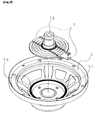
- Fig. 3 is a perspective view of a ring assembly with a damper, a terminal ring, and a voice coil.
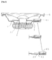
- Fig. 4 is a perspective view of the ring assembly and a speaker frame, before assembly.
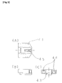
- Figs. 5A to 5C are plan, side, and front views showing the structure of a housing.
- Fig. 6 is a perspective view illustrating assembly processes of a housing with lead wires.
- Fig. 7 is a cross sectional view illustrating a mount process of the terminal ring and housing with lead wires, especially showing a holding member.
- Fig. 8 is a cross sectional view illustrating a mount process of the terminal ring and housing with lead wires, especially illustrating a process of mounting terminal lugs on the terminal ring.
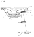
- Fig. 9 is a perspective view showing another embodiment of a speaker interconnection structure according to the present invention.
- Fig. 10 is a perspective view showing an example of a conventional speaker interconnection structure.
- Fig. 11 is a perspective view showing another example of a conventional speaker interconnection structure.
- a damper 1 with a conductive member is basically similar to the damper with a conductive member proposed by the present inventors.
- a damper cotton cloth is dipped in solution diluted with phenol and methanol of about 1 : 4.5, and is impregnated with phenol resin. After the solvent is evaporated to remove a tack nature of the resin, the cloth is cut to have a predetermined width. This cloth is used as the material of the damper 1 with a conductive member.
- a tin-copper alloy wire having a bus bar diameter of 0.1 mm is worked to a foil having a width of 0.32 mm and a thickness of 0.027 mm, and the foil is wound in a single layer at 22 +/- 2 turns/cm around paraaramid fibers of 200 denier to form a tinsel wire.
- a bundle of 13 tinsel wires is knitted flat at a knitting pitch of 27.45 +/- 0.82 mm/turn to form a flat knitted tinsel wire 2 having a width of about 2.2 mm, a thickness of 0.44 mm, and an electric resistance of 0.48 ⁇ /m.
- Two flat knitted tinsel wires 2 are sewn in parallel on the damper 1 at the positions spaced by 10.5 mm (a pitch of about 21 mm) from the center of the width of the cut woven cloth of the damper 1, by using a thread called cornex #40.
- the damper is then thermally molded to form a plurality of concentric and radially extending corrugations 11, with the flat knitted tinsel wires 2 traversing the corrugations 11.
- a damper 1 having a predetermined shape, with the flat knitted tinsel wires 2 being sewn as shown in Fig. 2.
- the outer diameter of the damper 1 is 78 mm, and the inner diameter of an opening at the junction 13 to a coil bobbin is 26.3 mm.
- Seven corrugations 11 of about 2.4 mm deep are disposed at a pitch of about 2.8 mm from the area near the opening, and an adhesive margin 12 of about 4 mm wide is formed at the outer peripheral portion of the damper.
- Two tongues 14 are formed in parallel outside of the adhesive margin 12 at the positions spaced by an equal distance from the center line of the damper, the tongue 14 being 29 mm wide and 7.7 mm long.
- the flat knitted tinsel wires 21 extend to the tongue 14.
- the flat knitted tinsel wires 2 become about 3 mm wide after the press molding.
- a terminal ring 3 made of insulating material such as resin is used, similar to Japanese Patent Laid-open Publication No. 6-337496 proposed by the present inventors.
- the terminal ring 3 has an inner diameter of 69.6 mm and an outer diameter of 79.2 mm.
- a tongue 31 having a width of 29.3 mm and a length of 8.3 mm such as shown in Fig. 2 is formed at the outer peripheral portion of the terminal ring.
- Recesses 34 are formed in the tongue 31 at the center thereof in the longitudinal direction, symmetrically with the center line of the ring at a pitch of 21 mm same as that of the flat knitted tinsel wires 2 sewn on the damper 1.
- the positions of the recesses 34 correspond to the ends of the flat knitted tinsel wires 2.
- the side walls of the recesses 34 are tapered so that terminal lugs 42 can enter the recesses 34 easily.
- a projected mount 32 for mounting a connector housing 41 extends outward from the tongue 31 along its center line.
- the projected mount 32 is 11.2 mm wide and 10 mm long.
- the distal end of the projected mount 32 is tapered so as to make it easy to insert the connector housing 41.
- a square hole 33 having a side length of 3.6 mm is formed at the position 5 mm inside the distal end along the center line of the terminal ring 3.
- the thickness of the terminal ring 3 is 2 mm, and in this embodiment, it is made of ABS resin.
- Rubber-based adhesive 36 is coated on the inner circumferential portion of the terminal ring 3 by a predetermined amount, and dried for a predetermined time to volatilize solvent of the adhesive. Thereafter, the terminal ring 3 is aligned with the adhesive margin 12 of the damper 1, and the tongue 14 of the damper 1 and the tongue 31 of the terminal ring 3 are aligned in position. The adhesive 36 is thermally reactivated by thermally pressing the adhesive margin 12 of the damper 1 to secure the terminal ring 3 to the adhesive margin 12.
- a voice coil 7 and the damper 1 with the terminal ring 3 are set on a setting jig 74, and the outer circumference of a coil bobbin 71 is inserted into the inner hole 13 of the damper 1 to assemble them.
- Two copper foil input electrodes 72 are attached to the outer circumference of the coil bobbin 71 at the predetermined positions corresponding to the flat knitted tinsel wires 2 of the damper 1.
- the coil bobbin 71 is inserted by aligning the copper foil electrodes 72 with the end portions 21 of the flat knitted tinsel wires extending to the inner hole 13 of the damper 1.
- the copper foil electrodes 72 at the outer circumference of the coil bobbin 71 are soldered to the end portions 22 of the flat knitted tinsel wires 2 extending to the edge of the inner hole 13 of the damper 1.
- An assembly jig used for this embodiment is not shown because the structure thereof is very complicated and hard to understand.
- Input lead wires 6 are vinyl parallel wires generally used.
- a conductor is made of a bundle of 20 metal wires such as copper wires each having a diameter of about 0.18 mm.
- the conductor is covered with an insulating film (in this embodiment, vinyl chloride resin) to form an insulated conductor having an outer diameter of about 2.6 mm.
- Two insulated conductors are integrated in parallel.
- the terminal lug 42 shown in Fig. 6 is formed with a press machine by working a thin plate of metal having a good conductivity such as copper alloy.
- the end portion of the terminal lug 42 is worked to have a shape shown in Fig. 6 by a press machine through drawing, bending, cutting, and the like.
- the insulating film at the end portion 61 of the input lead wire 6 is removed by about 5 mm to expose the conductor.
- the conductor at the end portion 61 of the input lead wire 6 is caulked at a caulking portion of the terminal lug 42.
- This caulking method is similar to a conventional fastening terminal connected to the end of an input lead, is widely used, has no problem in its quality, and is highly reliable.
- the connector housing 41 is made of injection molded resin. As shown in Figs. 5 and 6, two square holes 44 are formed at the same pitch as the flat knitted tinsel wires 2 of the damper 1, and an opening 43 is formed in correspondence with the projected mount 32 of the terminal ring 3.
- the terminal lugs 42 are fitted in the square holes 44, the front wall of the square hole 44 is aligned with the front (contact) area of the terminal lug 42, and the back wall of the square hole 44 is aligned with the caulked portion of the input lead wire 6.
- the terminal lug 42 at the end portion 61 of the input lead wire 6 is secured by the housing 41 to form a housing H with lead wires.
- the housing H with lead wires is mounted on the terminal ring 3 to complete electrical interconnection.
- the projected mount 32 of the terminal ring is inserted into the opening 43 formed near the bottom of the housing H with lead wires.
- a recess is formed in the wall of the square hole 44 inserted with the terminal lug 42 to expose the front (contact) area of the terminal lug 42. Therefore, as shown in Fig. 8, the front areas of the two terminal lugs 42 come in contact with the two flat knitted tinsel wires 2 extending to the outermost circumference of the damper 1.
- the end portion of the front area of each terminal lug 42 deforms and rides on the tapered portion of the ring terminal 3.
- the contact area of the terminal lug 42 positions above the recess 34. Therefore, the contact area once deformed restores the original shape by its elasticity and is pressed together with the flat knitted tinsel wire 2 into the recess 34 of the tongue 31 to complete electrical interconnection.
- a holding member 45 with a hook having an engaging claw is integrally formed on the upper wall of the opening 43 of the housing H with lead wires.
- the holding member 45 is used for preventing the housing H with lead wires from being dismounted. Therefore, when the housing H with lead wires is pushed in to the final position, the engaging claw of the holding member 45 engages with the square hole 33 of the projecting mount 32 as shown in the cross section of Fig. 7. As a result, the housing H will not be dismounted unless an external force larger than the holding member 45 is applied. By pushing the end of the hook of the holding member 45, the engaging claw can be disengaged from the square hole 33 to release the lock state, and the housing H with lead wires can be dismounted from the projecting mount 32 of the terminal ring 3.
- the holding member 45 is constructed as above. Since the terminal ring 3 is made of resin, a holding member 35 having a hook such as shown in Fig. 9 may be formed on the projecting mount 32 of the terminal ring 3.
- the housing 41 Since the shape of the housing 41 does not match the shape of a conventional speaker frame not using the terminal ring 3, the housing 41 cannot be used presently with a conventional speaker. However, in the future, in accordance with optimization and standardization of the shape of the terminal ring 3 and the shape of a conventional speaker frame 5, the terminal lug 42 and housing 41 can be designed. In this case, connectors can be formed matching both conventional speakers and invention speakers. In the perspective views of the drawings, a diaphragm and other elements are omitted for the simplicity of drawings.
- both the positive and negative terminal lugs 42 can be inserted at the same time, the number of insertion works is only one. Therefore, the interconnection work is easy, manpower can be reduced, and load during the interconnection work can be reduced considerably.
- the terminal lugs 54a and 54b are not necessary to be mounted on the terminal ring 3. Therefore, the number of steps for forming the ring assembly R can be reduced greatly, and so the number of steps for assembling a speaker can be reduced greatly.
- Terminal mounting steps in speaker assembly processes have been a bottleneck of speaker manufacture automation.
- this invention substantially dispenses with the terminal mounting steps and is very advantageous for automation of all processes of speaker manufacture. Since the terminal ring 3 is made of resin, a very complicated shape can be easily formed by injection molding or the like, in addition, the holding member for fixing a housing can be integrally formed with the terminal ring 3.
- the speaker interconnection structure of the present invention in the interconnection work, when the housing is mounted on the projecting mount of the terminal ring, the terminal lug held by the housing comes in contact with the end portion of the flat knitted tensile wire. Therefore, load on finger tips of a worker can be reduced considerably.
Landscapes
- Physics & Mathematics (AREA)
- Engineering & Computer Science (AREA)
- Acoustics & Sound (AREA)
- Signal Processing (AREA)
- Audible-Bandwidth Dynamoelectric Transducers Other Than Pickups (AREA)
- Details Of Audible-Bandwidth Transducers (AREA)
Applications Claiming Priority (2)
| Application Number | Priority Date | Filing Date | Title |
|---|---|---|---|
| JP171589/95 | 1995-06-15 | ||
| JP17158995A JP3336554B2 (ja) | 1995-06-15 | 1995-06-15 | スピーカの配線構造 |
Publications (1)
| Publication Number | Publication Date |
|---|---|
| EP0749262A1 true EP0749262A1 (fr) | 1996-12-18 |
Family
ID=15925966
Family Applications (1)
| Application Number | Title | Priority Date | Filing Date |
|---|---|---|---|
| EP96108874A Ceased EP0749262A1 (fr) | 1995-06-15 | 1996-06-03 | Haut-parleur avec structure d'interconnexion |
Country Status (3)
| Country | Link |
|---|---|
| EP (1) | EP0749262A1 (fr) |
| JP (1) | JP3336554B2 (fr) |
| DE (1) | DE749262T1 (fr) |
Families Citing this family (2)
| Publication number | Priority date | Publication date | Assignee | Title |
|---|---|---|---|---|
| JP3804925B2 (ja) | 2001-10-23 | 2006-08-02 | パイオニア株式会社 | スピーカのコネクタ |
| JP2005269335A (ja) | 2004-03-19 | 2005-09-29 | Pioneer Electronic Corp | スピーカ装置 |
Citations (4)
| Publication number | Priority date | Publication date | Assignee | Title |
|---|---|---|---|---|
| US4465905A (en) * | 1982-04-28 | 1984-08-14 | International Jensen Incorporated | Loudspeaker assembly |
| DE3318346A1 (de) * | 1983-05-20 | 1984-11-22 | Blaupunkt-Werke Gmbh, 3200 Hildesheim | Steckerhalter fuer kontaktstecker eines lautsprechers |
| EP0361642A2 (fr) * | 1988-09-24 | 1990-04-04 | Pioneer Electronic Corporation | Broche de connexion pour haut-parleur |
| EP0720415A2 (fr) * | 1994-12-28 | 1996-07-03 | Kabushiki Kaisha Kenwood | Composant de haut-parleur, haut-parleur, et procédé de sa fabrication |
-
1995
- 1995-06-15 JP JP17158995A patent/JP3336554B2/ja not_active Expired - Fee Related
-
1996
- 1996-06-03 DE DE1996108874 patent/DE749262T1/de active Pending
- 1996-06-03 EP EP96108874A patent/EP0749262A1/fr not_active Ceased
Patent Citations (4)
| Publication number | Priority date | Publication date | Assignee | Title |
|---|---|---|---|---|
| US4465905A (en) * | 1982-04-28 | 1984-08-14 | International Jensen Incorporated | Loudspeaker assembly |
| DE3318346A1 (de) * | 1983-05-20 | 1984-11-22 | Blaupunkt-Werke Gmbh, 3200 Hildesheim | Steckerhalter fuer kontaktstecker eines lautsprechers |
| EP0361642A2 (fr) * | 1988-09-24 | 1990-04-04 | Pioneer Electronic Corporation | Broche de connexion pour haut-parleur |
| EP0720415A2 (fr) * | 1994-12-28 | 1996-07-03 | Kabushiki Kaisha Kenwood | Composant de haut-parleur, haut-parleur, et procédé de sa fabrication |
Also Published As
| Publication number | Publication date |
|---|---|
| JP3336554B2 (ja) | 2002-10-21 |
| DE749262T1 (de) | 1997-08-28 |
| JPH099381A (ja) | 1997-01-10 |
Similar Documents
| Publication | Publication Date | Title |
|---|---|---|
| US6781059B2 (en) | Shielded wire | |
| EP1753095A1 (fr) | Adaptateur de connexion électrique et procédé de fabrication | |
| EP0675567B1 (fr) | Faisceau de câbles et procédé pour son fabrication | |
| US20060035523A1 (en) | Connector and cable retainer | |
| EP0749262A1 (fr) | Haut-parleur avec structure d'interconnexion | |
| JP5390792B2 (ja) | 接続部材 | |
| JP3916990B2 (ja) | リード線結線構造 | |
| JPH0578258B2 (fr) | ||
| JP2549583Y2 (ja) | フレキシブルプリント配線板 | |
| US6241549B1 (en) | Pressure-contact terminal and electric connection box containing pressure-contact terminals | |
| JPS6146007A (ja) | トランス | |
| JP3058502U (ja) | フラットフレキシブルケーブルおよびその端末処理部品 | |
| CN1138815A (zh) | 扬声器的布线结构 | |
| JP2019186075A (ja) | 端子とその端子が仮固定された部材を備えた組立体、及び、その組立体の製造方法 | |
| JPH09153387A (ja) | ジョイントコネクタの取付方法及び取付構造 | |
| JPH10155190A (ja) | スピーカの接続配線構造 | |
| JP3210784B2 (ja) | 圧接型コネクタ | |
| JPH089577A (ja) | モータ用電線端末処理装置 | |
| JP4071941B2 (ja) | フラットケーブル用穴あき板端子 | |
| JP3179213B2 (ja) | 連鎖端子 | |
| JP2022151329A (ja) | 端子、端子付き電線、およびワイヤハーネス | |
| JP3295221B2 (ja) | 絶縁被覆電線 | |
| KR20010083699A (ko) | 리본 케이블의 제조방법 | |
| US20030217861A1 (en) | Insulated wire splice | |
| JP2020202079A (ja) | 端子金具、及び、端子付き電線 |
Legal Events
| Date | Code | Title | Description |
|---|---|---|---|
| PUAI | Public reference made under article 153(3) epc to a published international application that has entered the european phase |
Free format text: ORIGINAL CODE: 0009012 |
|
| AK | Designated contracting states |
Kind code of ref document: A1 Designated state(s): DE FR GB |
|
| EL | Fr: translation of claims filed | ||
| 17P | Request for examination filed |
Effective date: 19970424 |
|
| DET | De: translation of patent claims | ||
| 17Q | First examination report despatched |
Effective date: 19981209 |
|
| GRAG | Despatch of communication of intention to grant |
Free format text: ORIGINAL CODE: EPIDOS AGRA |
|
| STAA | Information on the status of an ep patent application or granted ep patent |
Free format text: STATUS: THE APPLICATION HAS BEEN REFUSED |
|
| 18R | Application refused |
Effective date: 20010715 |