EP0747743B1 - Objectif de mesure, télécentrique des deux cÔtés - Google Patents
Objectif de mesure, télécentrique des deux cÔtés Download PDFInfo
- Publication number
- EP0747743B1 EP0747743B1 EP95108559A EP95108559A EP0747743B1 EP 0747743 B1 EP0747743 B1 EP 0747743B1 EP 95108559 A EP95108559 A EP 95108559A EP 95108559 A EP95108559 A EP 95108559A EP 0747743 B1 EP0747743 B1 EP 0747743B1
- Authority
- EP
- European Patent Office
- Prior art keywords
- optical system
- image
- objective
- measuring
- focal point
- Prior art date
- Legal status (The legal status is an assumption and is not a legal conclusion. Google has not performed a legal analysis and makes no representation as to the accuracy of the status listed.)
- Expired - Lifetime
Links
Images


Classifications
-
- G—PHYSICS
- G02—OPTICS
- G02B—OPTICAL ELEMENTS, SYSTEMS OR APPARATUS
- G02B13/00—Optical objectives specially designed for the purposes specified below
- G02B13/22—Telecentric objectives or lens systems
Definitions
- the invention relates to a bilaterally telecentric measuring lens for non-contact length measurement in two and three-dimensional space.
- the measurement accuracy of video measurement technology is directly dependent on the accuracy and stability of the parameters of the internal orientation. These parameters, the establishment of the relationship between the measured variable and the display of the measuring device, can be detected by calibrating inside the camera. However, whenever a measuring system is not only intended for a single measuring task and the position of the objects to be measured is not accurate can be maintained, the camera calibration means a time-consuming, additional load, because it must be carried out every time the measuring task is changed.
- optical systems which are designed to be telecentric on both sides.
- Such lenses consist of two optical subsystems, which have the same basic structure and between which an iris diaphragm is arranged.
- the elements of the second optical subsystem are arranged in the reverse order to the first optical subsystem.
- Such telecentric measuring lenses are afocal and therefore have a fixed imaging scale, which is independent of both the object and the image position.
- Such an afocal and telecentric lens is described in SU patent 935099.
- it due to its construction, it has pupillary aberration, i.e. H.
- pupillary aberrations i.e. H.
- not all of the main rays are telecentric. These pupil aberrations cause a change in the distortion when moving the object or image plane. This lens is therefore unsuitable for measuring purposes.
- GB patent 1423597 describes an afocal system for the transmission of markings which does not allow correction of pupil aberration and coma. It is therefore also unsuitable as a measuring lens.
- this object is achieved according to the features of claim 1 in that the two optical subsystems are arranged with respect to one another such that the rear focal point of the first subsystem coincides with the front focal point of the second subsystem.
- the imaging scale of the overall system is equal to the ratio of the focal lengths of the subsystems.
- the third link is a scattering meniscus, the convex side of which faces the object.
- An optical system constructed according to this principle has an aperture of at least 0.14 on the image side when it is used for the imaging. It is corrected for an image circle diameter of 0.2 * f'2, where f'2 is the focal length of the image-side subsystem.
- a variation of the object plane position is in a range of ⁇ 3 mm f'1 f'2 ) 2 possible without sacrificing image quality.
- the focal length of the subsystem on the object side is designated by f'1.
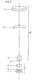
- the optical subsystem 1 shows a measuring lens which is telecentric on both sides and consists of an image-side optical subsystem 1 and an object-side optical subsystem 2 with a centrally arranged iris diaphragm 3 for the image scale -1 and an image-side aperture of 0.14.
- the optical subsystems 1, 2 each consist of a putty member 4 facing the measurement object or the image with a positive refractive power and a scattering putty surface.
- the middle link of the image or object-side subsystem 1, 2 is in each case a converging lens 5 made of a high-index crown glass.
- a scattering meniscus 6 Inside, opposite the iris diaphragm 3, there is a scattering meniscus 6, the convex side of which is the object or the Image is facing, arranged.
- the object-image distance is 284. Any object position within a distance range from 71 to 77 is permissible without having to accept losses in the imaging quality.
- the image-side optical subsystem 1 and the object-side optical subsystem 2 are determined by the following numerical data: r d n e ⁇ e 1. 130,882 9.60 1.4891 70.2 2nd -22,140 2.00 1.6072 37.8 3rd -127,464 3.10 4th 40,965 5.70 1.6413 55.1 5. -597.046 13.50 6. 28,247 11.39 1.5848 40.6 7. 15,845
- r means the radius of curvature of the corresponding one refractive lens surface
- d the distance between the refractive lens surfaces, measured on the optical axis.
- the position of the object plane can vary within a distance range from 185 to 209 without impairing the imaging quality.
- the object-image distance fluctuates between 467 and 485.
- the object-side subsystem 7 is determined by the following numerical data with the same construction as in the first exemplary embodiment: r d n e ⁇ e 1. 163,039 12:00 1.4891 70.2 2nd -42,468 4.00 1.6072 37.8 3rd -219,485 14.72 4th 53,840 11.40 1.6413 55.1 5. 96,899 42.58 6. 38.188 22.78 1.5848 40.6 7. 20,358
- the image-side optical subsystem 1 is the same as that described in the first exemplary embodiment.
- the position of the object plane can fluctuate within a distance range of 246 to 342 without impairing the imaging quality.
- the object-image distance moves between 505 and 595.
- the object-side optical subsystem 8 with the same construction as described in the first exemplary embodiment, is determined by the following numerical parameters: r d n e ⁇ e 1. 243,547 17.00 1.4996 66.7 2nd -88,326 8.60 1.6072 37.8 3rd -342,441 82.40 4th 72.157 12:00 1.6413 55.1 5. 78,537 163.70 6. 47,746 22.80 1.5848 40.6 7. 29,641
- the image-side optical subsystem 1 also corresponds here to that described in the first exemplary embodiment.
Landscapes
- Physics & Mathematics (AREA)
- General Physics & Mathematics (AREA)
- Optics & Photonics (AREA)
- Lenses (AREA)
- Length Measuring Devices By Optical Means (AREA)
Claims (4)
- Objectif de mesure télécentrique des deux côtés pour la mesure longitudinale sans contact dans l'espace bidimensionnel et tridimensionnel, formé de deux systèmes optiques partiels de même type dont les éléments individuels sont disposés en sens inverse les uns par rapport aux autres,
caractérisé en ce qu'un diaphragme à iris (3) est disposé entre les deux systèmes optiques partiels (1, 2) et les deux systèmes optiques partiels (1, 2) sont disposés l'un par rapport à l'autre pour que le foyer arrière du premier système partiel (1) coïncide avec le foyer avant du second (2), de sorte que l'échelle de représentation de l'ensemble du système global est égale au rapport des distances focales des systèmes partiels, en ce que les deux systèmes optiques partiels (1, 2) se composent chacun de trois éléments, le premier élément étant un élément de collage (4) qui est tourné vers l'objectif de mesure ou vers l'image, respectivement, qui présente une force de réfraction positive et qui comporte une surface de collage divergente, tandis que le deuxième élément consiste en une lentille convergente (5) en crown très réfringent et que le troisième élément consiste en un ménisque divergent (6) avec un côté convexe tourné vers l'objet ou vers l'image, respectivement, et en ce que la distance entre les lentilles convergentes (5) et les ménisques divergents (6) des systèmes optiques partiels (1, 2) est nettement supérieure à la distance entre les éléments de collage (4) et les lentilles convergentes (5). - Objectif de mesure télécentrique des deux côtés selon la revendication 1, caractérisé par un système optique partiel (1) situé côté image et par un système optique partiel (2) situé côté objet qui est défini par les paramètres numériques suivants :
r d ne νe 1. 130.882 9.60 1.4891 70.2 2. -22.140 2.00 1.6072 37.8 3. -127.464 3.10 4. 40.965 5.70 1.6413 55.1 5. -597.046 13.50 6. 28.247 11.39 1.5848 40.6 7. 15.845
Ecartement du foyer arrière : 23.20 - Objectif de mesure télécentrique des deux côtés selon la revendication 1, caractérisé par un système optique partiel (7) situé côté objet qui est défini par les paramètres numériques suivants :
r d ne νe 1. 163.039 12.00 1.4891 70.2 2. -42.468 4.00 1.6072 37.8 3. -219.485 14.72 4. 53.840 11.40 1.6413 55.1 5. 96.899 42.58 6. 38.188 22.78 1.5848 40.6 7. 20.358
Ecartement du foyer arrière : 28.07 - Objectif de mesure télécentrique des deux côtés selon la revendication 1, caractérisé par un système optique partiel (8) situé côté objet qui est défini par les paramètres numériques suivants :
r d ne νe 1. 243.547 17.00 1.4996 66.7 2. -88.326 8.60 1.6072 37.8 3. -342.441 82.40 4. 72.157 12.00 1.6413 55.1 5. 78.537 163.70 6. 47.746 22.80 1.5848 40.6 7. 29.641
Ecartement du foyer arrière : 4.75
Priority Applications (3)
| Application Number | Priority Date | Filing Date | Title |
|---|---|---|---|
| EP95108559A EP0747743B1 (fr) | 1995-06-03 | 1995-06-03 | Objectif de mesure, télécentrique des deux cÔtés |
| DE59500569T DE59500569D1 (de) | 1995-06-03 | 1995-06-03 | Beidseitig telezentrisches Messobjektiv |
| US08/659,044 US5708532A (en) | 1995-06-03 | 1996-06-03 | Double-sided telecentric measurement objective |
Applications Claiming Priority (1)
| Application Number | Priority Date | Filing Date | Title |
|---|---|---|---|
| EP95108559A EP0747743B1 (fr) | 1995-06-03 | 1995-06-03 | Objectif de mesure, télécentrique des deux cÔtés |
Publications (2)
| Publication Number | Publication Date |
|---|---|
| EP0747743A1 EP0747743A1 (fr) | 1996-12-11 |
| EP0747743B1 true EP0747743B1 (fr) | 1997-08-27 |
Family
ID=8219328
Family Applications (1)
| Application Number | Title | Priority Date | Filing Date |
|---|---|---|---|
| EP95108559A Expired - Lifetime EP0747743B1 (fr) | 1995-06-03 | 1995-06-03 | Objectif de mesure, télécentrique des deux cÔtés |
Country Status (3)
| Country | Link |
|---|---|
| US (1) | US5708532A (fr) |
| EP (1) | EP0747743B1 (fr) |
| DE (1) | DE59500569D1 (fr) |
Families Citing this family (34)
| Publication number | Priority date | Publication date | Assignee | Title |
|---|---|---|---|---|
| DE19739428A1 (de) * | 1997-09-09 | 1999-03-11 | Zeiss Carl Fa | Beleuchtungseinrichtung für ein Operationsmikroskop |
| US6198577B1 (en) * | 1998-03-10 | 2001-03-06 | Glaxo Wellcome, Inc. | Doubly telecentric lens and imaging system for multiwell plates |
| US6590852B1 (en) * | 1999-01-05 | 2003-07-08 | Call/Recall, Inc. | Massively-parallel writing and reading of information within the three-dimensional volume of an optical disk, particularly by use of a doubly-telecentric afocal imaging system |
| WO2001051887A1 (fr) | 2000-01-07 | 2001-07-19 | Cyberoptics Corporation | Systeme de profilometrie de phase dote d'un projecteur telecentrique |
| US6549647B1 (en) | 2000-01-07 | 2003-04-15 | Cyberoptics Corporation | Inspection system with vibration resistant video capture |
| US6593705B1 (en) | 2000-01-07 | 2003-07-15 | Cyberoptics Corporation | Rapid-firing flashlamp discharge circuit |
| EP1297688A4 (fr) * | 2000-04-21 | 2003-06-04 | Lockheed Corp | Systeme optique catadioptrique doublement telecentrique a profondeur etendue et a champ elargi pour mise en image numerique |
| US6476962B1 (en) | 2001-04-24 | 2002-11-05 | Eastman Kodak Company | Multi-beam zoom lens for producing variable spot sizes for a laser printer |
| JP3708845B2 (ja) * | 2001-06-19 | 2005-10-19 | 株式会社ミツトヨ | 両テレセントリック対物レンズ |
| JP4157305B2 (ja) * | 2002-02-13 | 2008-10-01 | 株式会社ミツトヨ | テレセントリックレンズ系および画像測定装置 |
| DE10249702A1 (de) * | 2002-10-25 | 2004-05-06 | Leica Microsystems (Schweiz) Ag | Zoomsystem |
| WO2008086016A1 (fr) * | 2007-01-10 | 2008-07-17 | Cyberoptics Corporation | Système d'inspection |
| US7896988B2 (en) * | 2007-06-15 | 2011-03-01 | Spectre Enterprises, Inc. | Charge system for destroying chips on a circuit board and method for destroying chips on a circuit board |
| US7876499B1 (en) * | 2007-11-30 | 2011-01-25 | Itt Manufacturing Enterprises, Inc. | Objective lens |
| US8059280B2 (en) | 2008-01-31 | 2011-11-15 | Cyberoptics Corporation | Method for three-dimensional imaging using multi-phase structured light |
| US7777871B2 (en) * | 2008-04-29 | 2010-08-17 | Acushnet Company | Apparatus for measuring physical properties of golf balls and cores |
| US8134719B2 (en) * | 2010-03-19 | 2012-03-13 | Carestream Health, Inc. | 3-D imaging using telecentric defocus |
| CN103339492B (zh) | 2010-12-01 | 2017-03-15 | 皇家飞利浦电子股份有限公司 | 具有双远心光学系统的传感器装置 |
| US9684149B2 (en) | 2012-08-07 | 2017-06-20 | Carl Zeiss Industrielle Messtechnik Gmbh | Coordinate measuring machine and method for determining spatial coordinates on a measurement object |
| US10126252B2 (en) | 2013-04-29 | 2018-11-13 | Cyberoptics Corporation | Enhanced illumination control for three-dimensional imaging |
| CN103345046B (zh) * | 2013-06-28 | 2015-05-20 | 中国科学院西安光学精密机械研究所 | 一种两档变倍光学系统 |
| US9995910B1 (en) | 2014-03-16 | 2018-06-12 | Navitar Industries, Llc | Optical assembly for a compact wide field of view digital camera with high MTF |
| US9726859B1 (en) | 2014-03-16 | 2017-08-08 | Navitar Industries, Llc | Optical assembly for a wide field of view camera with low TV distortion |
| US9091843B1 (en) | 2014-03-16 | 2015-07-28 | Hyperion Development, LLC | Optical assembly for a wide field of view point action camera with low track length to focal length ratio |
| US10545314B1 (en) | 2014-03-16 | 2020-01-28 | Navitar Industries, Llc | Optical assembly for a compact wide field of view digital camera with low lateral chromatic aberration |
| US10386604B1 (en) | 2014-03-16 | 2019-08-20 | Navitar Industries, Llc | Compact wide field of view digital camera with stray light impact suppression |
| US9316820B1 (en) | 2014-03-16 | 2016-04-19 | Hyperion Development, LLC | Optical assembly for a wide field of view point action camera with low astigmatism |
| US9494772B1 (en) | 2014-03-16 | 2016-11-15 | Hyperion Development, LLC | Optical assembly for a wide field of view point action camera with low field curvature |
| US10139595B1 (en) | 2014-03-16 | 2018-11-27 | Navitar Industries, Llc | Optical assembly for a compact wide field of view digital camera with low first lens diameter to image diagonal ratio |
| US9316808B1 (en) | 2014-03-16 | 2016-04-19 | Hyperion Development, LLC | Optical assembly for a wide field of view point action camera with a low sag aspheric lens element |
| JP6379649B2 (ja) * | 2014-05-09 | 2018-08-29 | コニカミノルタ株式会社 | 両側テレセントリック光学系 |
| CN107589531B (zh) * | 2017-10-10 | 2019-12-13 | 东莞万思自动化技术开发有限公司 | 一种红外光测径仪镜头 |
| CN108107557B (zh) * | 2018-01-10 | 2024-01-16 | 佛山华国光学器材有限公司 | 一种长工作距离的高倍率双侧远心镜头 |
| JP2021020249A (ja) * | 2019-07-30 | 2021-02-18 | 株式会社リコー | レーザユニットおよびレーザマーカおよびレーザ印字システム |
Family Cites Families (8)
| Publication number | Priority date | Publication date | Assignee | Title |
|---|---|---|---|---|
| GB1260923A (en) * | 1969-03-18 | 1972-01-19 | Szerszamgepipari Muevek | Improvements in telecentric lens systems |
| GB1248362A (en) * | 1970-01-28 | 1971-09-29 | Rank Organisation Ltd | Optical profile projection systems |
| GB1423597A (en) * | 1973-04-06 | 1976-02-04 | Zeiss Jena Veb Carl | Device for measuring movements of a first member relative to a second member |
| SU573790A1 (ru) * | 1976-03-03 | 1977-09-25 | Предприятие П/Я В-8872 | Телецентрический объектив |
| US4189211A (en) * | 1978-01-03 | 1980-02-19 | Kollmorgen Corporation | Wide angle telecentric projection lens assembly |
| SU909652A1 (ru) * | 1980-06-04 | 1982-02-28 | Центральный Ордена "Знак Почета" Научно-Исследовательский Институт Геодезии, Аэросъемки И Картографии Им.Ф.Н.Красовского | Репродукционный объектив |
| JPS6419317A (en) | 1987-07-14 | 1989-01-23 | Dainippon Screen Mfg | Telecentric image formation optical system with large picture plane size |
| JPH0442208A (ja) * | 1990-06-08 | 1992-02-12 | Dainippon Screen Mfg Co Ltd | テレセントリック投影レンズ |
-
1995
- 1995-06-03 DE DE59500569T patent/DE59500569D1/de not_active Expired - Lifetime
- 1995-06-03 EP EP95108559A patent/EP0747743B1/fr not_active Expired - Lifetime
-
1996
- 1996-06-03 US US08/659,044 patent/US5708532A/en not_active Expired - Lifetime
Also Published As
| Publication number | Publication date |
|---|---|
| US5708532A (en) | 1998-01-13 |
| DE59500569D1 (de) | 1997-10-02 |
| EP0747743A1 (fr) | 1996-12-11 |
Similar Documents
| Publication | Publication Date | Title |
|---|---|---|
| EP0747743B1 (fr) | Objectif de mesure, télécentrique des deux cÔtés | |
| DE112016000121B4 (de) | Endoskop-Vergrößerungsoptik und Endoskop | |
| DE3526872C2 (fr) | ||
| DE2601499C3 (de) | Varioobjektiv | |
| DE19858785C2 (de) | Endoskopobjektiv sowie Endoskop mit einem derartigen Objektiv | |
| EP0310640B1 (fr) | Systeme de lentilles de relais | |
| DE102019100944B4 (de) | Fotografisches Objektiv mit wenigstens sechs Linsen | |
| DE3447893C2 (fr) | ||
| DE2329200C2 (de) | Teleobjektiv | |
| DE10317942A1 (de) | Variolinsensystem | |
| DE10006644A1 (de) | Weitwinkeloptik | |
| DE102012214303B9 (de) | Optisches System zur Abbildung eines Objekts sowie Aufnahmeeinheit mit einem optischen System | |
| EP2808716B1 (fr) | Objectif photographique grand angle à mise au point interne | |
| DE102008042221B9 (de) | Optisches System sowie Fernrohr mit einem optischen System | |
| DE112017003378T5 (de) | Endoskopoptik | |
| DE2537058C3 (de) | Weitwinkelobjektiv vom Typ umgekehrter Teleobjektive | |
| DE3838168C2 (fr) | ||
| DE3817885C2 (fr) | ||
| DE4401364A1 (de) | Realbildsucher | |
| DE2520793A1 (de) | Vario-linsensystem | |
| EP1787154B1 (fr) | Objectif | |
| DE4431320C2 (de) | Kompaktes Varioobjektiv | |
| EP0916107B1 (fr) | Endoscope avec au moins un systeme d'inversion a indice de refraction non homogene | |
| DE2807653C2 (de) | Weitwinkel-Varioobjektiv | |
| DE2208282C3 (de) | Fernrohrlinsensystem mit kleinem Fernrohrverhältnis |
Legal Events
| Date | Code | Title | Description |
|---|---|---|---|
| GRAG | Despatch of communication of intention to grant |
Free format text: ORIGINAL CODE: EPIDOS AGRA |
|
| PUAI | Public reference made under article 153(3) epc to a published international application that has entered the european phase |
Free format text: ORIGINAL CODE: 0009012 |
|
| GRAH | Despatch of communication of intention to grant a patent |
Free format text: ORIGINAL CODE: EPIDOS IGRA |
|
| 17P | Request for examination filed |
Effective date: 19960628 |
|
| AK | Designated contracting states |
Kind code of ref document: A1 Designated state(s): DE |
|
| AX | Request for extension of the european patent |
Free format text: LT;LV;SI |
|
| GRAH | Despatch of communication of intention to grant a patent |
Free format text: ORIGINAL CODE: EPIDOS IGRA |
|
| GRAA | (expected) grant |
Free format text: ORIGINAL CODE: 0009210 |
|
| AK | Designated contracting states |
Kind code of ref document: B1 Designated state(s): DE |
|
| AX | Request for extension of the european patent |
Free format text: LT;LV;SI |
|
| REF | Corresponds to: |
Ref document number: 59500569 Country of ref document: DE Date of ref document: 19971002 |
|
| PLBE | No opposition filed within time limit |
Free format text: ORIGINAL CODE: 0009261 |
|
| STAA | Information on the status of an ep patent application or granted ep patent |
Free format text: STATUS: NO OPPOSITION FILED WITHIN TIME LIMIT |
|
| 26N | No opposition filed | ||
| PGFP | Annual fee paid to national office [announced via postgrant information from national office to epo] |
Ref country code: DE Payment date: 20120629 Year of fee payment: 18 |
|
| REG | Reference to a national code |
Ref country code: DE Ref legal event code: R119 Ref document number: 59500569 Country of ref document: DE Effective date: 20140101 |
|
| PG25 | Lapsed in a contracting state [announced via postgrant information from national office to epo] |
Ref country code: DE Free format text: LAPSE BECAUSE OF NON-PAYMENT OF DUE FEES Effective date: 20140101 |