EP0744575B1 - Structure - Google Patents
Structure Download PDFInfo
- Publication number
- EP0744575B1 EP0744575B1 EP94926382A EP94926382A EP0744575B1 EP 0744575 B1 EP0744575 B1 EP 0744575B1 EP 94926382 A EP94926382 A EP 94926382A EP 94926382 A EP94926382 A EP 94926382A EP 0744575 B1 EP0744575 B1 EP 0744575B1
- Authority
- EP
- European Patent Office
- Prior art keywords
- constituent units
- framework structure
- secondary constituent
- primary
- coupled
- Prior art date
- Legal status (The legal status is an assumption and is not a legal conclusion. Google has not performed a legal analysis and makes no representation as to the accuracy of the status listed.)
- Expired - Lifetime
Links
- 239000000470 constituent Substances 0.000 claims description 459
- 238000010168 coupling process Methods 0.000 claims description 97
- 238000005859 coupling reaction Methods 0.000 claims description 97
- 230000008878 coupling Effects 0.000 claims description 93
- 239000007787 solid Substances 0.000 claims description 73
- 230000008602 contraction Effects 0.000 claims description 13
- 239000010410 layer Substances 0.000 description 14
- 238000010276 construction Methods 0.000 description 13
- 238000000034 method Methods 0.000 description 13
- 230000008569 process Effects 0.000 description 5
- QNRATNLHPGXHMA-XZHTYLCXSA-N (r)-(6-ethoxyquinolin-4-yl)-[(2s,4s,5r)-5-ethyl-1-azabicyclo[2.2.2]octan-2-yl]methanol;hydrochloride Chemical compound Cl.C([C@H]([C@H](C1)CC)C2)CN1[C@@H]2[C@H](O)C1=CC=NC2=CC=C(OCC)C=C21 QNRATNLHPGXHMA-XZHTYLCXSA-N 0.000 description 4
- 230000009471 action Effects 0.000 description 4
- 230000005540 biological transmission Effects 0.000 description 4
- 239000012530 fluid Substances 0.000 description 4
- 230000004048 modification Effects 0.000 description 4
- 238000012986 modification Methods 0.000 description 4
- 230000006641 stabilisation Effects 0.000 description 4
- 238000011105 stabilization Methods 0.000 description 4
- 238000010420 art technique Methods 0.000 description 3
- 230000008859 change Effects 0.000 description 3
- 230000000630 rising effect Effects 0.000 description 3
- 239000002356 single layer Substances 0.000 description 3
- XEEYBQQBJWHFJM-UHFFFAOYSA-N Iron Chemical compound [Fe] XEEYBQQBJWHFJM-UHFFFAOYSA-N 0.000 description 2
- 239000011521 glass Substances 0.000 description 2
- 239000000463 material Substances 0.000 description 2
- 238000013459 approach Methods 0.000 description 1
- 230000000694 effects Effects 0.000 description 1
- 239000003365 glass fiber Substances 0.000 description 1
- 238000005286 illumination Methods 0.000 description 1
- 229910052742 iron Inorganic materials 0.000 description 1
- 229910052751 metal Inorganic materials 0.000 description 1
- 239000002184 metal Substances 0.000 description 1
- 150000002739 metals Chemical class 0.000 description 1
- 229920005989 resin Polymers 0.000 description 1
- 239000011347 resin Substances 0.000 description 1
- 230000000087 stabilizing effect Effects 0.000 description 1
- 239000002023 wood Substances 0.000 description 1
Images


Classifications
-
- E—FIXED CONSTRUCTIONS
- E04—BUILDING
- E04B—GENERAL BUILDING CONSTRUCTIONS; WALLS, e.g. PARTITIONS; ROOFS; FLOORS; CEILINGS; INSULATION OR OTHER PROTECTION OF BUILDINGS
- E04B1/00—Constructions in general; Structures which are not restricted either to walls, e.g. partitions, or floors or ceilings or roofs
- E04B1/32—Arched structures; Vaulted structures; Folded structures
- E04B1/3211—Structures with a vertical rotation axis or the like, e.g. semi-spherical structures
-
- E—FIXED CONSTRUCTIONS
- E04—BUILDING
- E04B—GENERAL BUILDING CONSTRUCTIONS; WALLS, e.g. PARTITIONS; ROOFS; FLOORS; CEILINGS; INSULATION OR OTHER PROTECTION OF BUILDINGS
- E04B1/00—Constructions in general; Structures which are not restricted either to walls, e.g. partitions, or floors or ceilings or roofs
- E04B1/32—Arched structures; Vaulted structures; Folded structures
-
- E—FIXED CONSTRUCTIONS
- E04—BUILDING
- E04B—GENERAL BUILDING CONSTRUCTIONS; WALLS, e.g. PARTITIONS; ROOFS; FLOORS; CEILINGS; INSULATION OR OTHER PROTECTION OF BUILDINGS
- E04B1/00—Constructions in general; Structures which are not restricted either to walls, e.g. partitions, or floors or ceilings or roofs
- E04B1/343—Structures characterised by movable, separable, or collapsible parts, e.g. for transport
- E04B1/344—Structures characterised by movable, separable, or collapsible parts, e.g. for transport with hinged parts
- E04B1/3441—Structures characterised by movable, separable, or collapsible parts, e.g. for transport with hinged parts with articulated bar-shaped elements
-
- E—FIXED CONSTRUCTIONS
- E04—BUILDING
- E04H—BUILDINGS OR LIKE STRUCTURES FOR PARTICULAR PURPOSES; SWIMMING OR SPLASH BATHS OR POOLS; MASTS; FENCING; TENTS OR CANOPIES, IN GENERAL
- E04H12/00—Towers; Masts or poles; Chimney stacks; Water-towers; Methods of erecting such structures
- E04H12/18—Towers; Masts or poles; Chimney stacks; Water-towers; Methods of erecting such structures movable or with movable sections, e.g. rotatable or telescopic
- E04H12/187—Towers; Masts or poles; Chimney stacks; Water-towers; Methods of erecting such structures movable or with movable sections, e.g. rotatable or telescopic with hinged sections
-
- E—FIXED CONSTRUCTIONS
- E04—BUILDING
- E04H—BUILDINGS OR LIKE STRUCTURES FOR PARTICULAR PURPOSES; SWIMMING OR SPLASH BATHS OR POOLS; MASTS; FENCING; TENTS OR CANOPIES, IN GENERAL
- E04H15/00—Tents or canopies, in general
- E04H15/32—Parts, components, construction details, accessories, interior equipment, specially adapted for tents, e.g. guy-line equipment, skirts, thresholds
- E04H15/34—Supporting means, e.g. frames
- E04H15/44—Supporting means, e.g. frames collapsible, e.g. breakdown type
- E04H15/48—Supporting means, e.g. frames collapsible, e.g. breakdown type foldable, i.e. having pivoted or hinged means
- E04H15/50—Supporting means, e.g. frames collapsible, e.g. breakdown type foldable, i.e. having pivoted or hinged means lazy-tongs type
-
- E—FIXED CONSTRUCTIONS
- E04—BUILDING
- E04B—GENERAL BUILDING CONSTRUCTIONS; WALLS, e.g. PARTITIONS; ROOFS; FLOORS; CEILINGS; INSULATION OR OTHER PROTECTION OF BUILDINGS
- E04B1/00—Constructions in general; Structures which are not restricted either to walls, e.g. partitions, or floors or ceilings or roofs
- E04B1/32—Arched structures; Vaulted structures; Folded structures
- E04B2001/3235—Arched structures; Vaulted structures; Folded structures having a grid frame
- E04B2001/3241—Frame connection details
-
- E—FIXED CONSTRUCTIONS
- E04—BUILDING
- E04B—GENERAL BUILDING CONSTRUCTIONS; WALLS, e.g. PARTITIONS; ROOFS; FLOORS; CEILINGS; INSULATION OR OTHER PROTECTION OF BUILDINGS
- E04B1/00—Constructions in general; Structures which are not restricted either to walls, e.g. partitions, or floors or ceilings or roofs
- E04B1/32—Arched structures; Vaulted structures; Folded structures
- E04B2001/3294—Arched structures; Vaulted structures; Folded structures with a faceted surface
Definitions
- This invention relates to framework structures which can be utilized for antennas, power transmission line poles, net support poles, illumination towers, advertisement towers and other poles and towers; building structures, furniture, tents, space structures and like structures, and temporary construction works therefor; bridges and like structures, and temporary construction works therefor; and various toys.
- Prior art structures which are capable of being expanded and contracted include the following structures (a) to (f):
- the above prior art structures have the following drawbacks.
- the structures in (a) are capable of being only telescoped, i.e., developed form only uni-dimensionally.
- the structures in (b) cannot readily transmit a moment via a hinge. Besides, theoretically they are readily subject to buckling when they experience compressive forces.
- the structures in (c) are capable of being changed in form from a uni-dimensional one to a three-dimensional one. However, they are subject to concentration of exerted force at their radial center. This means that they cannot readily transmit moment as a framework.
- the structures in (d) are capable of being inflated and shrunk three-dimensionally and have high degree of freedom of inflating and shrinkage. However, they are scarcely rigid because they have resort to fluid for their inflating and shrinkage.
- the structures in (e) are for two-dimensional development, and their rotary parts are weak to stresses applied thereto from different planes. Therefore, the scope of their utility is limited.
- the structures in (f) use structures in (e) limitatively in side-by-side stationary arrangements in such a manner that they are three-dimensionally rigid.
- they are applicable to jacks, chairs, etc. which can withstand three-dimensionally exerted loads.
- EP-A-0 455 850 discloses a expansion/retraction framework structure comprised of at least three scissors-like constituent units. Each unit is formed by two diagonal elements which have a central and two terminal pivot points which do not lie on a straight line. Each two diagonal elements are pivotally joint at their central pivot points. The units in turn are connected by couplers wherein each unit is pivotally joint at a terminal point of the diagonal elements to the coupler and the rotation axis of this terminal pivot point is parallel to the rotation axis of the central pivot point of the respective unit.
- a framework structure comprises a plurality of primary constituent units each including two rigid diagonal members constituting the diagonals of a quadrangular lateral face of a solid, at least one of two opposed side pairs of the quadrangular lateral face being parallel, the two diagonal members being coupled together for relative rotation about a first rotation axis passing through the intersection of the diagonals, the primary constituent units being coupled to one another in a ring-like fashion by coupling an end of each diagonal member in each primary constituent unit by a coupler to an associated end of a diagonal member of an adjacent primary constituent unit, wherein the coupler has a plurality of coupling members coupled together for relative rotation about a second rotation axis, an end of one of the diagonal members being coupled to each of the coupling members for rotation about a third rotation axis parallel to the first rotation axis, adjacent ones of the primary constituent units being thereby coupled together about the second rotation axis.
- each of the primary constituent units includes two diagonal members constituting the diagonals of a square or rectangular lateral face of a solid, and the first rotation axis of each primary constituent unit divides the segment of each of its diagonal members between the two third rotation axes with a ratio of 1: 1.
- each of the primary constituent units includes two diagonal members constituting the diagonals of an isosceles trapezoidal lateral face of a solid, and the first rotation axis of each primary constituent unit divides the segment of each of its diagonal members between the two third rotation axes with an equal ratio, the large and the small parts of the division ratio being disposed in the same orientation.
- each of the primary constituent units includes two diagonal members constituting the diagonals of an isosceles trapezoidal lateral face of a solid, and the first rotation axis of each primary constituent unit divides the segment of each of its diagonal members between the two third rotation axes with an equal ratio, the large and the small parts of the division ratio being disposed in the reverse orientation, alternately.
- each of the primary constituent units includes two diagonal members constituting the diagonals of an isosceles trapezoidal lateral face of a solid, and the first rotation axis of each primary constituent unit divides the segment of each of its diagonal members between the two third rotation axes with two different ratios, the primary constituent unit with the two different ratios of division being coupled together alternately.
- a framework structure according to the invention as set forth in any one of claims 6 to 17, comprises a plurality of secondary constituent units each constituted by one framework structure according to any one of claims 2 to 5, the secondary constituent units being coupled together in the direction of an axis passing through the center thereof or in the direction perpendicular to an axis passing through the center thereof or in both of these directions with couplers used in common or with a primary constituent unit used in common between adjacent ones of the secondary constituent units.
- a framework structure according to the invention as set forth in claims 18 to 20, comprises four different kinds of secondary constituent units constituted by respective framework structures according to claims 2 to 5, the secondary constituent units of a plurality of selected kinds among the four different kinds being coupled to one another in the direction of an axis passing through the center thereof or in the direction perpendicular to an axis passing through the center thereof with couplers used in common or with a primary constituent unit used in common between adjacent ones of the secondary constituent units.
- a framework structure according to the invention as set forth in claim 21, comprises four different kinds of secondary constituent units constituted by respective framework structures according to claims 2 to 5, adjacent ones of the secondary constituent units of a selected kind or a plurality of selected kinds among the four different kinds being coupled together via a pair of couplers coupled together for relative rotation about a fourth rotation axis perpendicular to second rotation axes of the pair couplers, adjacent primary constituent units being disposed between the two adjacent secondary constituent units and coupled together for relative rotation about the fourth rotation axis.
- a framework structure according to the invention as set forth in claim 22, comprises a polyhedron with all or some of lateral faces thereof each constituted by the framework structure according to claim 1, the framework structures being disposed with their bases aligned with each other, adjacent ones of the framework structures being coupled together via adjacent couplers coupled together for relative rotation about a fifth rotation axis.
- a framework structure comprises a plurality of primary constituent units each including two rigid diagonal members constituting the diagonals of a quadrangular lateral face of a solid, at least one of two opposed side pairs of the quadrangular lateral face being parallel, the two diagonal members being coupled together for relative rotation about a first rotation axis passing through the intersection of the diagonals, the primary constituent units being coupled to one another in a ring-like fashion by coupling an end of each diagonal member in each primary constituent unit by a coupler to an associated end of a diagonal member of an adjacent primary constituent unit, wherein some of the couplers each include a first coupling member coupled to the associated diagonal member for relative rotation about a seventh rotation axis extending in the axial direction of the associated diagonal member and a second coupling member coupled to the first coupling member for rotation about a sixth rotation axis perpendicular to the seventh rotation axis.
- a framework structure according to the invention as set forth in claim 24, comprises a plurality of secondary constituent units of type 9 each constituted by the framework structure according to claim 19, the secondary constituent units being coupled together with a plurality of primary constituent units used in common between adjacent ones of them, the secondary constituent units each disposed on each or some lateral faces of a polyhedron in a developed form of the framework structure.
- a framework structure according to the invention as claimed in claim 25, includes an additional 1 feature in the framework structure according to any one of claims 1 to 24, wherein a tension element is passed between mated ends of the two diagonal members of each primary constituent units such as to prevent relative rotation of the two diagonal members when an external force is exerted to the structure, thus making the structure rigid.
- a framework structure according to the invention as set forth in claim 27, comprises the framework structure according to any one of claims 1 to 24, wherein at least two wires are passed as tension elements around wire passing members provided on mated ends of the two diagonal members of a primary constituent unit or on two couplers such that one of the wires is led along a route for expansion and that another one of the wires is led along a route for contraction, the structure being expanded into a two-dimensional form by pulling the wire led along the route for expansion, the structure being contracted into a uni-dimensional form by pulling the wire led along the route for contraction.
- a framework structure according to the invention as set forth in claim 28, comprises a framework structure according to claim 26 or 27, wherein the diagonal members in each primary constituent unit are made from pipes, the wire or wires being led through the pipes.
- the framework structure according to the invention comprises a plurality of primary constituent elements or units U each, as shown in FIGS. 48(A) to 48(D), including two bar-like rigid diagonal members constituting the diagonals of a quadrangular lateral face of a solid such as a prism and a pyramid frustum, in which at least one of two opposed side pairs of the lateral face are parallel.
- the pair diagonal members u of each lateral face are coupled together for relative rotation in the form of letter X at the intersection of the diagonals.
- the diagonal members u may be made of metals, wood, resins, glass, and like materials.
- first rotation axis P1 The intersection of diagonals noted above is hereinafter referred to as "first rotation axis P1" of the primary constituent unit U.
- each unit U is located on each lateral face.
- four primary constituent units U are coupled to one another likewise.
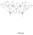
- adjacent primary constituent units U i.e., the associated ends of the diagonal members u of the adjacent primary constituent units U, are coupled to one another by couplers J as shown in a developed form in FIG. 49.
- FIG. 48(A) shows a triangular prism.
- FIG. 48(B) shows a quadrangular prism.
- FIG. 48(C) shows a triangular pyramid frustum.
- FIG. 48(D) shows a quadrangular pyramid frustum.
- a prism or a pyramid frustum having three base angles is advantageous from a dynamic point of view.
- the invention is applicable to a prism or a pyramid frustum having four or more base angles as well. That is, the prism or pyramid frustum may be quadrangular, pentangular, and further multangular with greater numbers of base angles as well.
- a prism is a polyhedron with a top and a base lying in parallel planes and with all the lateral faces being parallelograms (including squares and rectangles, the same being applied hereinafter).
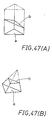
- the term "prism” has a broader meaning; it covers a solid having non-parallel base a and top b and quadrangular (i.e., trapezoidal) lateral faces with only one of the two opposed side pairs being parallel, as shown in FIG. 47(A).
- the pyramid frustum is a solid which is obtained by cutting away a top portion of a prism along a plane parallel to the base a, as shown in FIG. 47(B).
- the base a of the pyramid frustum and the cut face (top) b thereof are parallel and similar to each other.
- the lateral faces are each quadrangular, i.e., trapezoidal, with only one of the two opposed side pairs being parallel.
- none of opposed sides are parallel. This case of solid is outside the subject matter of the invention.
- the solids that belong to the subject matter of the invention are required to have quadrangular lateral faces with at least one of the two opposed side pairs being parallel, i.e., have trapezoidal lateral faces (with one parallel opposed side pair) or parallelogrammic lateral faces (with two parallel opposed side pairs).
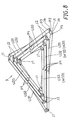
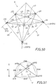
- a triangular pyramid frustum as shown in FIG. 50 which has parallel equilateral triangular bases, or base and top, with the circumcircle centers thereof connected to each other by a perpendicular line.
- the three lateral faces are congruent isosceles trapezoids as mentioned before.
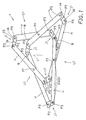
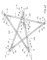
- a structure A is formed by three primary constituent units U1, U2 and U3 provided respectively on the three lateral faces of the above triangular pyramid frustum.
- the primary constituent units U1, U2 and U3 include diagonal members u1, u2 and u3 which constitute the diagonals of the isosceles trapezoids and thus have the same length.
- the pair diagonal members are coupled together for relative rotation at the intersection of the diagonals, i.e., about a first rotation axis P1, in the form of letter X.
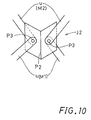
- the three primary constituent units U1, U2 and U3 are coupled to one another by couplers J into a ring-like form. More specifically, as shown in the drawing, the primary constituent units U1 and U2 are coupled together by couplers J12, the primary constituent units U2 and U3 are coupled together by couplers J23, and the primary constituent units U3 and U1 are coupled together by couplers J31.
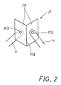
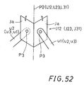
- the six couplers J (J12, J23 and J31) have the same structure. Specifically, as shown in FIG. 52, each coupler J (i.e., J12, J23 or J31) has two coupling parts Ja which overlap adjacent lateral faces of the triangular pyramid frustum and which are coupled together for relative rotation about a second rotation axis P2.
- the second rotation axis P2 is considered as conforming to each of the intersections L12, L23 and L31 of adjacent lateral faces.
- An end of each of the diagonal members ul, u2 and u3 of the primary constituent units U1, U2 and U3 is pin-coupled for rotation to each of the coupling parts Ja of the coupler J.
- the rotation axis of the end of the diagonal member u i.e., the center of the pin-coupling
- the third rotation axis P3 are parallel to the first rotation axes P1.
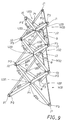
- the structure A comprises three primary constituent units U1, U2 and U3 coupled to one another by the couplers J into a ring-like form, the primary constituent units each including the pair rigid diagonal members u constituting the diagonals of the isosceles trapezoidal lateral face of the triangular pyramid frustum and coupled together by pin-coupling for relative rotation about the first rotation axis P1 (i.e., passing through the diagonal intersection).
- Each coupler J has a total of three rotation axes, i.e., one second rotation axis P2 and two third rotation axes P3. Two adjacent primary constituent units U are coupled together for relative rotation about a second rotation axis P2.
- Each diagonal member u has each end pin-coupled about a third rotation axis P3 to the corresponding lateral face of the triangular pyramid frustum.
- the structure A thus constitutes a three-dimensional torus which is formed by coupling the primary constituent units U to one another by pin-coupling about the second and third rotation axes P2 and P3, the primary constituent units U each being formed by coupling the pair diagonal members u together by pin-coupling for relative rotation about the first rotation axis P1.
- each of the pair diagonal members u always divides the length of the other in a ratio of 1 : ⁇ .
- the first rotation axis P1 divides the length of each of the two diagonal members u in a ratio of 1 : ⁇ . This ratio is hereinafter referred to as "division ratio ⁇ of diagonal member u".
- H SQR[ ⁇ (1 + ⁇ )sin( ⁇ /2) ⁇ 2 - ⁇ (1 - ⁇ )cos( ⁇ /2)tan ⁇ 2 ].
- the intersection angle ⁇ is about 21.8° from the above equations.
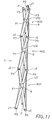
- This mathematically means that when the intersection angle ⁇ between the two diagonal members u becomes about 21.8°, the structure A assumes a two-dimensionally expanded form, that is, it is folded into a planar form with the base, top and three lateral faces of the triangular pyramid frustum lying in the same plane. This form of the structure will be hereinafter referred to as the "most expanded form".
- the structure A assumes a uni-dimensionally contracted form in which the distance between the base and top of the triangular pyramid frustum is maximum, that is, it is contracted to a substantially straight form.
- This uni-dimensionally contracted form of the structure A is hereinafter referred to as the "most contracted form”.
- the structure A is in the two-dimensional form when the intersection angle ⁇ in the primary constituent units U satisfies the above relations, and is brought to the uni-dimensional form when ⁇ becomes 180°.
- the structure can three-dimensionally undergo continuous expansion and contraction as the intersection angle ⁇ between the two extremes changes.
- a tension element is effectively provided to the top and/or the base of the structure for the stabilization thereof.
- a tensile force is exerted to the top and/or the base of the framework structure, or where compressive forces are exerted to the lateral faces thereof
- tension elements are effectively provided such that they extend in the edge directions of the structure.
- compressive or tensile forces may be exerted in any of the above directions, tension elements are effectively provided with respect to both the top/bottom direction and the edge direction.
- tension elements may suitably be provided along the sides indicated by triangle marks for the stabilization purpose.
- tension elements are effectively provided along the sides indicated by circle marks for the same purpose.
- the tension elements may be iron bars, wires, guts, glass fibers, panel glass, films, springs, electromagnetic forces, etc.
- Any of the framework structures with the above tension elements provided in the above ways constitutes a three-dimensional torus which is highly rigid and which has high mechanical strength.
- action of rigid members may further be provided on the localities as indicated by the triangle marks. This arrangement permits stabilization of the structure against both the tensile and compressive forces.
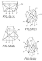
- the features of the invention as described above are obtainable not only with the structure A which comprises the three primary constituent units U1, U2 and U3 constituting the lateral faces of a triangular pyramid frustum, but also with prisms and pyramid frustums having greater base angle numbers. This is true not only with prisms and pyramid frustums but also with solids of other shapes, such as those shown in FIGS. 53(A) to 53(D) obtained by cutting away a top portion of a wedge-shaped solid or an obelisk along a plane parallel to the base, so long as the quadrangular lateral faces each have at least one parallel opposed side pair.
- a quadrangular pyramid frustum By coupling together four isosceles trapezoids into a ring-like form with the short and the long sides all disposed in the same orientation at the top and the bottom, respectively, a quadrangular pyramid frustum can be obtained.
- a shape as shown in FIG. 53(A) is formed. This shape corresponds to a solid obtained by cutting away a top portion of a wedge-like solid, and it can provide higher mechanical strength than a pyramid frustum.
- the base angle number is even. At any rate, it is possible to provide a structure which, with the same angle number, is less subject to deformation and more rigid than a pyramid frustum.
- the length ratio ⁇ between the upper and lower sides may be varied by varying the division ratio ⁇ of the diagonal members u, i.e., by varying the position of the first rotation axis P1 (or diagonal intersection point).
- a solid shown in FIG. 53(C) has a hexagonal base, and is obtained by coupling together six trapezoidal faces with the short and the long sides thereof disposed in the reverse orientation at the top and the bottom, alternately. This solid is a modification of the solid shown in FIG. 53(A).
- a solid shown in FIG. 53(D) again has a hexagonal base, but is obtained by coupling together, into a ring-like form of circle symmetry, six primary constituent units U having different member division ratios ⁇ . This solid is a modification of the solid shown in FIG. 53(B).
- a solid which is constituted by primary constituent units U with diagonal members u constituting diagonals may be other than a prism or a pyramid frustum so long as each of the lateral faces of the solid is a quadrangle with at least one parallel opposite side pair.
- Japanese Patent Publication No. 53-18815 Japanese Laid-Open Patent Publication No. 57-192700, Japanese Laid-Open Patent Publication No. 53-7912 and Japanese Laid-Open Patent Publication No. 63-255435, for instance, show techniques which are seemingly similar to the present invention.
- These prior art techniques are quite irrelevant to the present invention in purpose, constitution, function and effect, and a person having an ordinary knowledge in the art cannot be readily obtain the invention from these prior art techniques. This is so because primarily the prior art techniques are irrelevant to any torus structure capable of being expanded or contracted. It is thus impossible to provide any structure to which mechanical strength as torus can be given in any intermediate or final stage of expansion or contraction.
- Japanese Patent Publication No. 53-18815 is irrelevant to any structure which is a prerequisite element of the present invention, that is, a structure with two rigid diagonal members coupled together as a pair for relative rotation about a first rotation axis.
- the disclosed technique is irrelevant to any torus structure (without any member rigid in any direction). Therefore, the disclosed technique cannot provide a mechanical strength sufficient to apply to large-scale building structures or the like.
- the publication neither shows nor suggests this prerequisite element of the invention.
- Japanese Laid-Open Patent Publication No. 57-192700 does not show any second rotation axis as another prerequisite element of the present invention.
- Japanese Laid-Open Patent Publication No. 53-7912 is irrelevant to any torus structure. This technique does not have any second and fourth rotation axes disclosed in the present invention, so that the development is limited only to cylindrical forms and vice versa.
- Japanese Laid-Open Patent Publication No. 63-255435 discloses a technique concerning plate structures. This technique, however, is irrelevant to any structure capable of being folded into a uni-dimensional structure. Besides, the technique is irrelevant to any torus structure.
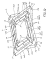
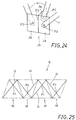
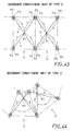
- FIGS. 43 to 46 are schematic developed views showing framework structures (hereinafter referred to merely as structures) as set forth in claims 2 to 5.
- FIG. 43 shows an example of structure as set forth in claim 2.
- This structure comprises a plurality of primary constituent units U each including pair diagonal members u constituting the diagonals of a rectangular lateral face of a polygonal prism and pin-coupled together for relative rotation about a first rotation axis P1 passing through the intersection of diagonals.
- This structure will hereinafter be referred to as "secondary constituent unit of type 2".
- FIG. 44 partly shows an example of the structure as set forth in claim 3.
- This structure comprises a plurality of primary constituent units U each including pair diagonal members u constituting the diagonals of an isosceles trapezoidal lateral face of a solid and pin-coupled together for relative rotation about a first rotation axis P1 passing through the intersection of diagonals.
- This structure will be hereinafter referred to as "secondary constituent unit of type 3".
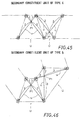
- FIG. 45 partly shows an example of the structure as set forth in claim 4.
- this structure comprises a plurality of primary constituent units U each including pair diagonal members constituting the diagonals of an isosceles trapezoidal lateral face of a solid.
- This structure will be hereinafter referred to as "secondary constituent unit of type 4".
- This structure will be hereinafter referred to as "secondary constituent unit of type 5".
- the ratios of 2 : 1 and 3 : 2 are shown as independent ratios for each of the primary constituent units.
- a structure 1 of this embodiment comprises three primary constituent units U1 each including two diagonal members u constituting the diagonals of an isosceles trapezoidal lateral face of a triangular pyramid frustum.
- the diagonal members u in each primary constituent unit U are pin-coupled together in the form of letter X for relative rotation about a first rotation axis P1 passing through the intersection of diagonals.
- the diagonal members u are rigid bar-like members having the same dimensions.
- the structure 1 is thus a secondary constituent unit of type 3.
- the three primary constituent units U1 are coupled to one another by couplers J into a ring-like form about an axis L shown in FIG. 1.
- the axis L will also be referred to as an "axis L of the structure (or secondary constituent unit to be described later".
- the direction along the axis L is referred to merely as "height direction”.
- the X- and Y-axis directions perpendicular to the Z axis are referred to as "transversal direction” and "longitudinal direction", respectively.
- the couplers J are all the same. An end of a diagonal member u in each primary constituent unit U1 is coupled by each coupler J to the associated end of a diagonal member u in an adjacent primary constituent unit U1.
- the coupler J has two coupling members Ja which are pin-coupled together for relative rotation about a second rotation axis P2.
- the second rotation axis P1 is coincident with a side common to adjacent lateral faces, or the intersection of the two faces, of a solid (triangular pyramid frustum). This is true as well in each of the following embodiments. In practical structures, however, the second rotation axis P2 may not be coincident with the intersection of adjacent lateral faces. This will be described later in detail.
- the coupler J has a third rotation axis P3 perpendicular to each of the coupling members Ja, and each diagonal member u in each primary constituent unit U1 has each end pin-coupled to each coupling member Ja for relative rotation about each third rotation axis P3.
- the third rotation axis P3 is parallel to the first rotation axis P1.
- the coupler J which has the two coupling members Ja will be hereinafter referred to as "coupler J of type 1". Two adjacent diagonal members u are coupled together by this coupler J1 of type 1.
- one diagonal member u in a certain primary constituent unit U will be considered.
- the ratio ⁇ of division of the diagonal members u is lU/lD.
- the first rotation axis P1 in each primary constituent unit U1 divides the segment of each diagonal member u between the opposite end third rotation axes P3 with a ratio of 2 : 1.
- the intersection angle ⁇ between the two diagonal members u does not refer to the angle between the like segments lU (or lD) of the two diagonal members u but refers to the angle between the segment lU of one diagonal member u and the unlike segment lD of the other diagonal member u.
- the minimum diagonal intersection angle ⁇ that is, when it is most contracted in the direction of the axis L
- it is referred to be in the "most expanded form” when it is in a form with the maximum diagonal intersection angle ⁇ (i.e., in the form in which it is most contracted to be straight in the direction of the axis L), it is referred to be in the "most contracted form".
- each primary constituent unit U1 is contracted in a rising fashion toward a straight or uni-dimensional form, that is, the structure 1 is contracted from the most expanded form shown in FIG. 1 three-dimensionally in the axis L direction. In other words, this results in an increase of the height H of the triangular pyramid frustum.
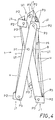
- FIG. 3 shows the structure 1 in an intermediate form between the two extreme forms.
- the diagonal intersection angle ⁇ becomes 180°.
- this form is the perfectly uni-dimensionally contracted form.
- the couplers J1 are ultimately brought into contact with each other. Therefore, the diagonal intersection angle does not actually become 180°, that is, the structure is not perfectly uni-dimensionally contracted.
- the structure 1 of the first embodiment (i.e., secondary constituent unit of type 3) is a basic one of the structures of various types according to the invention.
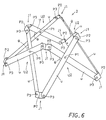
- a structure 2 of this embodiment comprises four primary constituent units U2 each including two diagonal members u constituting the diagonals of an isosceles trapezoidal lateral face of a quadrangular pyramid frustum.
- four primary constituent units U1 like those in the first embodiment are coupled to one another into a ring-like form.
- adjacent primary constituent units U2 are coupled together by couplers J1 of type 1 (see FIG. 2).
- This structure 2 again can be expanded into a two-dimensional form (i.e., the most expanded form) as shown in FIG. 5, in which each of the primary constituent units U2 lies in the same plane. Also, each primary constituent unit U2 is contracted in a rising fashion as the diagonal intersection angle ⁇ is increased by external forces exerted to its diagonal members u in a direction to bring third rotation axes P3 on the same upper or lower side toward each other.
- FIG. 6 shows the structure 2 in an intermediate contracted form.
- the structure 2 assumes a form closest to the uni-dimensionally contracted form (i.e., the most contracted form).
- the structure 2 can be expanded and contracted three-dimensionally between the most expanded form shown in FIG. 5 and the most contracted form shown in FIG. 7.
- the structure 2 (i.e., secondary constituent unit of type 3) is a basic one of the structures of various types according to the invention.
- the structures 1 and 2 of the first and second embodiments are examples of the invention as set forth in claim 3.
- FIGS. 8 to 11 This embodiment is an example of the invention as set forth in claim 7.
- a structure 3 of this embodiment comprises three secondary constituent units M31, M32 and M33 which are coupled to one another in the axis L direction, and each comprise three primary constituent units U3 each including two diagonal members u constituting the diagonals of an isosceles trapezoidal lateral face of a triangular pyramid frustum.
- the primary constituent units U3 in each secondary constituent unit are coupled to one another by couplers J1 of type 1 and also with couplers J2, which will be hereinafter referred to as of type 2, into a ring-like form.
- the three secondary constituent units M31, M32 and M33 are each a secondary constituent unit of type 3, i.e., the structure 1 of the first embodiment.
- These secondary constituent units M31, M32 and M33 comprise three primary constituent units U31, three constituent units U32 and three constituent units U33, respectively.
- the ratio ⁇ of division by the first rotation axis P1 in each of the primary constituent units U31, U32 and U33, is different from that in the structure 1 of the first embodiment.
- the structure 3 is shown in its two-dimensionally expanded or most expanded form in FIG. 8, in its uni-dimensionally contracted or most contracted form in FIG. 10, and in its intermediate form between the two extreme forms in FIG. 9.
- couplers J1 of type 1 are coupled together by couplers J1 of type 1.
- couplers J2 of type 2 will be hereinafter referred to as "couplers J2 of type 2".
- the coupler J2 of type 2 couples together a total of four diagonal members u, two of which are coupled together for relative rotation about one third rotation axis P3.
- two diagonal members u are pin-coupled together for relative rotation about one third rotation axis P3.
- the three secondary constituent units M31, M32 and M33 are coupled to one another in the axis L direction with three couplers J2 of type 2, each having one second rotation axis P2 and two third rotation axes P3, used in common between adjacent ones M31 and M32 (or M32 and M33).
- Two or four or more secondary constituent units M may be coupled together likewise.
- a parallelogram (or a square) P1 P3 P1 P3 is defined between each primary constituent unit U31 of the lower secondary constituent unit M31 and the opposed primary constituent unit U32 of the intermediate secondary constituent unit M32.
- l U2 l D3
- a parallelogram (or a square) P1 P3 P1 P3 is defined between opposed primary constituent units U32 and U33.
- the diagonal members u in each of the primary constituent units U31, U32 and U33 constitute diagonals of a trapezoid.
- the structure assumes the two-dimensionally expanded form, i.e., the most expanded form, as shown in FIG. 8.
- the structure assumes the most uni-dimensional form, i.e., the most contracted form, as shown in FIG. 11.
- the structure can be expanded and contracted three-dimensionally.
- the structure 3 of this embodiment like the structures 1 and 2 described above, is not brought to a perfectly uni-dimensionally contracted form.
- FIGS. 12 to 14 This embodiment is a different example of the invention as set forth in claim 7.
- a structure 4 of this embodiment comprises three secondary constituent units M41, M42 and M43 which are coupled to one another in the axis L direction and each comprise four primary constituent units U4 each including two diagonal members u constituting the diagonals of an isosceles trapezoidal lateral face of a quadrangular pyramid frustum.
- the primary constituent units U4 in each constituent unit are coupled to one another by couplers J1 of type 1 or couplers J2 of type 2 as noted above into a ring-like form.
- the three secondary constituent units M41, M42 and M43 again each constitute a secondary constituent unit of type 3 as noted above.
- the structure 4 of this embodiment is obtained by coupling together the structures 2 of the second embodiment (i.e., secondary constituent units of type 3) as the three secondary constituent units M4 in the axis L direction.
- the ratio ⁇ of division by the first rotation axis P1 in the primary constituent units U41, U42 and U43, is different from that in the structure 2 of the second embodiment.
- each of the secondary constituent units M31, M32 and M33 is formed by using four primary constituent units, instead of three units U31, U32 and U33 in the structure 3 of the third embodiment.
- the structure 4 is shown in its most two-dimensional form, i.e., the most expanded form, in FIG. 12, and in its most uni-dimensional form, i.e., the most contracted form, in FIG., 14. It is shown in an intermediate form between the two extreme forms in FIG. 13.
- the lower secondary constituent unit M41 includes four primary constituent units U41
- the intermediate secondary constituent unit M42 includes four secondary constituent units U42
- the upper secondary constituent units M43 includes four primary constituent units U43.
- the coupling of the primary constituent units U41, U42 and U43 between the secondary constituent units M41 and M42 and also between the secondary constituent units M42 and M43 is the same as in the structure 3 of the third embodiment.
- the ratio ⁇ of division by the first rotation axis P1 is equal.
- four parallelograms are formed by diagonal members u between the secondary constituent units M42 and M43.
- the structure 4 again is capable of being expanded and contracted between the most expanded form shown in FIG. 12 and the most contracted form in FIG. 14.
- This structure 4 permits assembling of a high voltage power transmission line tower or the like without need of any high locality operation by coupling together a number of diagonal members u on the ground as the structure 4 in the most contracted form as shown in FIG. 12, then expanding the structure by applying a predetermined external force thereto to an intermediate form as shown in FIG. 13, and then securing the structure 4 in this form.
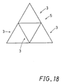
- FIGS. 15 to 20 A fifth embodiment will now be described with reference to FIGS. 15 to 20.
- This embodiment is an example of the invention as set forth in claim 15.
- a structure 5 of this embodiment comprises three structures 3 of the third embodiment. As shown in FIG. 18, the structures 3 are coupled together in a direction perpendicular to their axes L, which are perpendicular to the plane of paper in Fig. 18, (i.e., direction of the plane of paper), that is, in their transversal and longitudinal directions, into a ring-like form.
- Couplers J3 and J4 of types 3 and 4 as well as couplers J1 and J2 of types 1 and 2 are used for coupling the structures to one another.
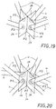
- the coupler J3 of type 3 includes four coupling members Ja which each have a third rotation axis P3 and which are coupled to one another for independent rotation about a second rotation axis P2 as a common rotation axis. That is, the coupler J3 is constituted by two couplers J1 of type 1 which are coupled together with the second rotation axis P2 as a common rotation axis.
- Four diagonal members u are pin-coupled to the coupler J3 of type 3 for independent rotation about their respective third rotation axes P3.
- these couplers J3 of type 3 are used to couple together adjacent ones of the structures 3 at the upper and lower ends of the structure 5.
- the coupler J4 of type 4 includes four coupling members Ja having a third rotation axis P3 and coupled together for independent rotation about a second rotation axis P2 as a common rotation axis.
- two diagonal members u are coupled for rotation about each of the four third rotation axes P3, that is, a total of eight diagonal members u are coupled to each coupler J4 of type 4.
- the couplers J4 is constituted by two couplers J2 of type 2 coupled together with the second rotation axis P2 as a common rotation axis.
- This coupler J4 of type 4 is used at the locality at which a secondary constituent unit M is coupled to adjacent ones in the axis L direction and also in the direction perpendicular thereto, that is, both in the longitudinal and transversal directions.
- the structure 5 can be three-dimensionally expanded and contracted between the most expanded form as shown in FIG. 15 (with each structure 3 in the most expanded form) and the most contracted form as shown in FIG. 17 (with each structure 3 in the most contracted form).
- the structure 5 is shown in its intermediate form between the two extreme forms in FIG. 16. Like the structure 4, this structure 5 permits assembling of, for instance, a high tension transmission line tower, without need of any high locality operation.
- a structure 6 of this embodiment comprises secondary constituent units of type 3 (i.e., structures 2 of the second embodiment) used as first secondary constituent units M61 and secondary constituent units of type 4 used as second secondary constituent units M62, the first and second secondary constituent units M61 and M62 being coupled together alternately in a two-dimensional fashion in directions perpendicular to the axis L direction, i.e., in transversal and longitudinal directions.
- the lateral faces of the structure 6, constituted by respective primary constituent units U have first rotation axes P1 located alternately at upper and lower positions.
- the coupling of the primary constituent units U in the secondary constituent units M61 and M62 and the coupling of these secondary constituent units M61 and 62, are made by using couplers J5 of type 5 to be described later in addition to couplers J1 and J3 of types 1 and 3 as noted above.
- the coupler J5 of type 5 includes three coupling members Ja each having a third rotation axis P3 and coupled together for independent rotation about a second rotation axis P2 as a common rotation axis.
- One diagonal member u is coupled to each third rotation axis P3.
- couplers J1 of type 1 are used at the eight corners, couplers J5 of type 5 are used at other ends, and couplers J3 of type 3 are used for other localities.
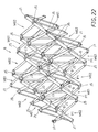
- the structure 6 having the above construction is brought to the most contracted form by minimizing the distance between the third rotation axes P3 in each primary constituent unit U, i.e., maximizing the diagonal intersection angle ⁇ in each primary constituent unit U.
- This form is shown in FIG. 21.
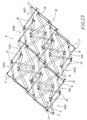
- the structure 6 is developed three-dimensionally to assume consequent intermediate forms shown in FIGS. 22 and 23 and eventually reach the most expanded form close to a substantial two-dimensional form with a minimum diagonal intersection angle ⁇ .
- each primary constituent unit U is changed in form in a rising fashion, and the structure 6 assumes consequent intermediate forms as shown in FIGS. 23 and 22 to eventually reach the most contracted form as shown in FIG. 21.
- the structure 6 may be used to form a torus structure constituting, for instance, the floor of a large-scale building structure, by compactly assembling it to a form m as shown in FIG. 21 on the ground, then suspending it and then developing it in space.
- the structure 6 may be used to form a three-dimensional torus structure used for space structure by assembling it to the most contracted form, i.e., the most compact form, then bringing it out from the atmosphere, and then developing it to cause action of tension elements.
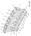
- a seventh embodiment will now be described with reference to FIGS. 26 to 28.
- This embodiment is an example of the invention as set forth in claim 19.
- a structure 7 of this embodiment comprises first secondary constituent units M71 and second secondary constituent units M72, these units M71 and M72 being coupled together alternately in a direction perpendicular to their axes L, i.e., in a transversal direction thereof.
- the first secondary constituent units M71 each include primary constituent units, each of which includes diagonal members u constituting the two diagonals of a lateral face of a solid with isosceles trapezoidal lateral faces.
- a segment of each diagonal member u between two third rotation axes P3 is divided by a first rotation axis P1 with a ratio of 2 : 1.
- the primary constituent units in this secondary constituent unit M71 are coupled to one another in a ring-like form such that their long and short divided parts appear alternately.
- These secondary constituent units M71 correspond to the secondary constituent unit of type 4 as set forth in claim 4.
- the second secondary constituent units M72 likewise each include primary constituent units, each of which includes diagonal members u constituting the two diagonals of a lateral face of a solid with isosceles trapezoidal lateral faces, the primary constituent units being coupled together in a ring-like form.
- a segment of each diagonal member u between two third rotation axes P3 is divided by a first rotation axis P1 with a ratio of 1 : 1 or 2 : 1.
- the primary constituent units with a division ratio of 2 : 1 and those with a division ratio of 1 : 1 appear alternately.
- These secondary constituent units M72 correspond to the secondary constituent unit of type 5 as set forth in claim 5.
- the arrangement of the secondary constituent unit of type 5 is such that the primary constituent units with a division ratio of 2 : 1 are combined alternately with those with a division ratio of 1 : 1.
- the first and second secondary constituent units M71 and M72 are coupled together alternately in a direction perpendicular to the axis L direction (i.e., in a transversal or left-right direction as viewed in the drawing) with one primary constituent unit used in common between adjacent ones of them.
- the primary constituent units divided into the division ratios of 1 : 2 and 1 : 1 are arranged alternately.
- the coupling of the first and second secondary constituent units M71 and M72 adjacent to each other is made by a coupler J5 of type 5 as noted above.
- the structure 7 having the above construction is shown in its most contracted form in FIG. 26.
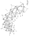
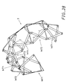
- an external force is exerted to the structure 7 in this form in a direction of reducing the diagonal intersection angle ⁇ of each primary constituent unit, it is changed in form to assume an intermediate form as shown in FIG. 27 and eventually reach the most expanded form, i.e., an arch-like form, as shown in FIG. 28.
- the structure 7 is returned via the intermediate form shown in FIG. 27 to the most contracted form shown in FIG. 26.
- This structure 7 may be used as a structure unit or a drive of a bridge or a building structure, for instance, by assembling it to the most contracted form as shown in FIG. 26 and then exerting an external force thereto to be developed into the arch-like form as shown in FIG. 27 or 28. Like the structure 6, the structure 7 may also be used to form a structure for space structures.
- a structure 8 of this embodiment comprises a plurality of the structures 7 of the seventh embodiment, which are coupled to one another alternately in a longitudinal direction such that the long and the short sides of lateral faces appear at the top and the bottom alternately. More specifically, the first and second secondary constituent units M71 and M72 of the seventh embodiment are coupled together alternately in both transversal and longitudinal directions.
- a lateral face in which primary constituent units U with a division ratio of 2 : 1 and those with a division ratio of 1 : 1 appear alternately, and a lateral face in which primary constituent units with a division ratio of 2 : 1 and those with the inverse division ratio appear alternately, are adjacent to one another.
- the coupling of the secondary constituent units M71 and M72 is made by using couplers J1, J3 and J5 of types 1, 3 and 5.
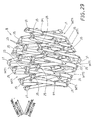
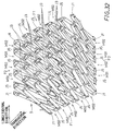
- the structure 8 having the above construction is shown in its most contracted form in FIG. 29.
- the structure 8 is changed in form to assume an intermediate form as shown in FIG. 30 and eventually reach the most expanded form, i.e., a vault-like form, as shown in FIG. 31.
- FIGS. 32 to 34 A ninth embodiment will now be described with reference to FIGS. 32 to 34. Again, this embodiment is an example of the invention as set forth in claim 19.
- a structure 9 of this embodiment comprises first secondary constituent units M91 which are the secondary constituent units of type 3 (the structures 2) and second secondary constituent units M92 which are the secondary constituent units of type 4. Specifically, what are obtained by coupling the first secondary constituent units M91 to one another in the same vertical orientation in a transversal direction, and what are obtained by coupling the second secondary constituent units M92 to one another in the same vertical orientation in a transversal direction, are coupled to one another alternately in a longitudinal direction.
- a lateral face F2 in which primary constituent units with a division ratio of 2 : 1 appear in alternate inverse vertical orientations are adjacent to one another. r .
- Couplers J1 of type 1 are used at a total of eight corners of the top and the bottom, and like the sixth or the eighth embodiment, the coupling of the secondary constituent units M91 and M92 is made by using couplers J3 and J5 of types 3 and 5.
- the structure 9 having the above construction is shown in FIG. 32 in its most contracted form with a maximum diagonal intersection angle ⁇ of each primary constituent unit U.
- a force is exerted to the structure 9 in this most contracted form in a direction of reducing the diagonal intersection angle ⁇ , i.e., increasing the distance between the third rotation axes P3, the structure 9 is changed in form three-dimensionally to assume an intermediate form as shown in FIG. 33 and eventually reach the most expanded form with a minimum diagonal intersection angle ⁇ .
- the most expanded form is a vault-like form as in the structure 8.
- the structure 9, as well as the structure 8, can be used as a three-dimensional torus structure for various large-scale building structures by assembling it to the compact and most contracted form, and then expanding it to the most expanded form or an intermediate form therebefore, thus providing for the action of tension elements noted above, if necessary.
- a three-dimensional torus for instance, a structure which is straight in one of the X and Y directions and has a face arrangement of variable curvature of radius in the other direction, or a structure having a spiral sectional profile.
- FIGS. 35 to 37 A tenth embodiment will now be described with reference to FIGS. 35 to 37.
- This embodiment is an example of the invention as set forth in claim 21.
- the structure 10 comprises three vertical stages, i.e., a lower stage constituted by secondary constituent units M101 of type 2, a middle stage constituted by secondary constituent units M102 of type 3, and an upper stage constituted by secondary constituent units M103 of type 3.
- the structure 10 uses couplers J6 of type 6 for the coupling between the secondary constituent units M101 and the secondary constituent units M102 and also the coupling between the secondary constituent units M102 and the secondary constituent units M103, so that the structure 10 can assume a substantially cylindrical form.
- the lower stage secondary constituent units M101 of type 2 each include a plurality of primary constituent units U101 having a division ratio ⁇ of unity and coupled to one another into a ring-like form.
- the coupling of the primary constituent units U101 is made by using couplers J1 of type 1.
- the middle stage secondary constituent units M102 of type 3 each include a plurality of primary constituent units U102 having a division ratio ⁇ of 2/3 and coupled to one another into a ring-like form.
- the coupling of the primary constituent units U102 is made by using couplers J1 of type 1.
- the upper stage secondary constituent units M103 of type 3 each include a plurality of primary constituent units U103 having a division ratio ⁇ of 0.5 and coupled to one another into a ring-like form.
- the coupling of the primary constituent units U103 is made by using couplers J1 of type 1.
- the coupler J6 of type 6 has a structure including two couplers J1 of type 1 coupled together about a fourth rotation axis P4. More specifically, the coupler J6 includes two couplers J6', each of which has two coupling members Ja coupled together for relative rotation about a second rotation axis P2 as a common axis and a further coupling member Jb. The two couplers J6' have their coupling members Jb coupled together for relative rotation about a fourth rotation axis P4. To each of the coupling members Ja, one diagonal member u is coupled for rotation about a third rotation axis P3. The fourth rotation axis P4 is perpendicular to each second rotation axis P2. The two second rotation axes P2 each of the two coupling members Ja lie in the same plane, that is, they are for relative rotation about the fourth rotation axis P4 in the same plane.
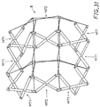
- the secondary constituent units M101, M102 and M103 are expanded as a whole to assume an intermediate form as shown in FIG. 36 and eventually reach the most expanded form (not shown).
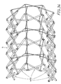
- the structure 10 is uni-dimensionally contracted to assume a form as shown in FIG. 35 and eventually reach the most contracted form, which is a substantially cylindrical form.
- the structure 10 is three-dimensionally expanded and contracted between the most contracted form and the most expanded form, and, as shown in FIG. 36, it forms a dome-like structure in its intermediate form.
- This structure 10 again may be used as a structure constituting, for instance, a dome-like roof of a building by assembling together the number of primary constituent units U101, U102 and U103 as shown above and then developing the structure to the dome-like form as shown in FIG. 36.
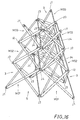
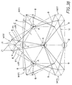
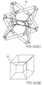
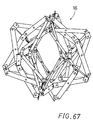
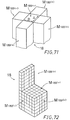
- a structure 11 of this embodiment comprises five secondary constituent units Mill located on the respective lateral faces of a regular hexahedron C other than the base thereof.
- the secondary constituent units M111 are coupled to one another by couplers J7 of type 7 and also by couplers J8 of type 8.
- Each of the secondary constituent units M111 is substantially the same in structure as the above structure 2 (see FIG. 7). Specifically, it includes four primary constituent units U111 (only two thereof being shown) which are coupled to one another into a ring-like form, and each constitute a lateral face of a quadrangular pyramid frustum and have two diagonal members u mutually coupled for relative rotation about a first rotation axis P1.
- the primary constituent units U111 are coupled to one another by couplers J1 of type 1.
- each coupler J7 of type 7 includes a main coupler J71 having three coupling members J711, and six sub-couplers J712 each coupled to each side of the coupling members J711 for rotation about a fifth rotation axis P5.
- the three coupling members J711 of the main coupler J71 are sheet-like members secured together at an angle of 120 ⁇ between adjacent ones of them.
- Each coupling member J711 has the fifth rotation axis P5 about which each sub-coupler J712 coupled to each side of the coupling member J711 is rotatable.
- each sub-coupler J712 has paired coupling members Ja coupled together for relative rotation about a second rotation axis P2.
- An end of a diagonal member u is coupled to one of the paired coupling members Ja of the sub-coupler J712 for rotation about a third rotation axis P3, and the other coupling member Ja is coupled to each coupling member J711 of the main coupler J71 for rotation about a fifth rotation axis P5.
- the coupler J7 of type 7 thus couples together six diagonal members u.
- the three secondary constituent units M111 are coupled to one another with one coupler J7 of type 7 as described above used for each of four parts A in FIG. 38. These parts A correspond to the four upper corners of the regular hexahedron C.
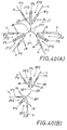
- the coupling structure in part A is shown schematically in FIG. 40(A).
- this coupler J8 of type 8 has a structure constituted by two of the coupling members J711 of the main coupler J71 of the above coupler J7 of type 7. More specifically, the coupler J8 of type 8 includes a main coupler J81 having two coupling members J811, and four sub-couplers J812 each coupled to each side of each coupling member J811 for rotation about a fifth rotation axis P5.
- One end of a diagonal member u is coupled to one coupling member Ja of each sub-coupler J812 for rotation about a third rotation axis P3, and the other coupling member Ja is coupled to each coupling member J811 for rotation about a fifth rotation axis P5.
- the structure 11 of this embodiment comprises five secondary constituent units M111 which are coupled to one another by using the couplers J7 of type 7 and the couplers J8 of type 8.
- the structure 11 of this embodiment is brought closer to the most expanded form by applying external force thereto in the direction of reducing the intersection angle ⁇ of each primary constituent unit U111, it is deformed into a substantially semi-spherical dome.
- While this embodiment has concerned with the structure comprising the five secondary constituent units M111 each located on each lateral face of a regular hexahedron C, this is by no means limitative; for example, the structures 1 as described above or other structures constituting pentangular pyramid frustums, triangular pyramid frustums, etc. may be disposed such that each constitutes each face of a regular or pseudo regular polyhedron having 12 or 20 faces or a cube or other polyhedrons and be coupled together by using predetermined couplers.
- the coupler 7 of type 7 described above may be used by increasing or reducing, if necessary, the number of the sub-couplers J712 or the number of the coupling members J711 in the main coupler J71.
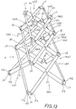
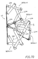
- a 12th embodiment will now be described with reference to FIGS. 41 and 42.
- This embodiment is an example of the invention as set forth in claim 23.
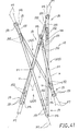
- a structure 12 of this embodiment comprises three primary constituent units U120 each located on a rectangular lateral face of a triangular prism.
- Each primary constituent unit U120 includes paired diagonal members u constituting the diagonals of the face and coupled together into the form of letter X for rotation about a first rotation axis P1 at the intersection of the diagonals.
- the diagonal members u are made from a sufficiently rigid pipe; a pipe of the same size is used for all the six diagonal members u of the three primary constituent units U120.
- the two diagonal members u in each primary constituent unit U120 are coupled together with a division ratio of 1 : 1 at the first rotation axis P1.
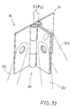
- the three primary constituent units U120 are coupled to one another by a total of six couplers J9 of type 9 into a ring-like form.
- Each coupler J9 includes coupling members J91 which are each obtained by separating end portions of each diagonal member u to a predetermined length, adjacent coupling members J91 being coupled together for relative rotation about a sixth rotation axis P6.
- the sixth rotation axis P6 is perpendicular to the axes of the two coupling members J91 which pass through apexes of the triangular prism and which are coupled together (i.e., the axes of the two diagonal members u).
- Each coupling member J91 has an integral coaxial coupling bar J92 at its separated end.
- the coupling bar J92 is rotatably inserted in a bore ua of a diagonal member u extending from the associated end thereof.
- Each coupling member J91 is thus coaxially coupled to each diagonal member u.
- Each coupling member J91 is thus rotatable about the axis of the associated diagonal member u. This axis of rotation of the coupling member J91 will hereinafter be referred to as a seventh rotation axis P7.
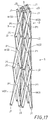
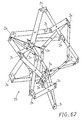
- the structure 12 having the above construction can be three-dimensionally expanded and contracted between the two-dimensionally expanded state (i.e., most expanded form) and the uni-dimensionally contracted form (i.e., most contracted form).
- the structure 12 is shown in a form close to the most contracted form in FIG. 41 and in a form close to the most expanded form in FIG. 42.
- the structure 12 can be held in a predetermined stable state by appropriately providing tension elements or compressive elements along edges of the triangular prism.
- Such a structure may be utilized for various building structures or the like.
- the diagonal members u may be made from pipes, but they may be made of solid bars or square bars instead of pipes. While the structure 12 of this embodiment has been described in relation to a triangular prism, this is by no means limitative, and the invention is applicable to other prisms or pyramid frustums as well. Furthermore, it is possible to develop the structure into a more complicated structure by combining a plurality of structures 12 each as an secondary constituent unit.
- a 13th embodiment which is an example of the invention as set forth in claim 19 will now be described with reference to FIGS. 54 and 55.
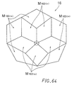
- a structure 13 of this embodiment comprises a combination of secondary constituent units, which are one version of secondary constituent units of type 3 constituting a solid (pentangular pyramid frustum) having pentagonal base and lateral faces (hereinafter referred to as "secondary constituent unit M136 of type 6"), and those which are one version of secondary constituent units of type 4 constituting a solid (hexangular pyramid frustum) having hexagonal base and lateral faces (hereinafter referred to particularly as “secondary constituent unit M137 of type 7").
- the secondary constituent unit M136 of type 6 includes primary constituent units U136, each of which constitute each lateral face of a pentangular pyramid frustum and have paired diagonal members u coupled together for relative rotation about a first rotation axis P1.
- the primary constituent units U136 of type 6 have an equal ratio ⁇ of division of the diagonal members u by the first rotation axis P1 between opposite end third rotation axes P3, and are coupled to one another such that the large and the small parts of their division ratio ⁇ are disposed in the same orientation.
- the secondary constituent unit M137 of type 7 includes primary constituent units U137, each of which constitutes each lateral face of a hexangular pyramid frustum and have paired diagonal members u coupled together for relative rotation about a first rotation axis P1.
- the primary constituent units P137 have an equal ratio ⁇ of division of the diagonal members u by the first rotation axis P1 between the third rotation axes P3, and are coupled to one another such that the large and the small parts of the division ratio ⁇ are disposed in the reverse orientation, alternately.
- pluralities of the two different kinds of secondary constituent units M136 and M137 are coupled to one another in a direction perpendicular to the axes of these units M136 and M137 (i.e., the direction of the plane of paper in FIG. 54) with a primary constituent unit U136 (or U137) used in common between adjacent secondary constituent units.
- the structure 13 is shown in its uni-dimensionally contracted form or the most contracted form in the schematic plan view of FIG. 54 and in a dome-like intermediate form in FIG. 55.
- the structure 13 comprises three secondary constituent units M136 of type 6 and ten secondary constituent units M137 of type 7.
- the three intermediate constituent units M136 of type 6 are each coupled with respect to every other one of six lateral faces of one secondary constituent unit M137 of type 7.
- FIG. 55 shows only part of the structure 13, i.e., only three secondary constituent units M136 of type 6 and four secondary constituent units M137 of type 7. Adjacent secondary units M136 and M137 are coupled together by using the above coupler J5 of type 5.
- this structure 13 is two-dimensionally expanded to the most expanded form by applying an external force thereto in the direction of reducing the intersection angle ⁇ of the primary constituent units U136 and U137 in the secondary constituent units M136 and M137.
- the structure 13 is two-dimensionally expanded, it eventually assumes a dome-like form having a double layer structure as shown in FIG. 55.
- the structure is uni-dimensionally contracted to the most contracted form, that is, it eventually assumes a form as shown in FIG. 54.
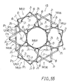
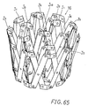
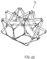
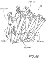
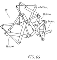
- a 14th embodiment which is also an example of the invention as set forth in claim 19 will now be described with reference to FIGS. 56 to 59.
- a structure 14 of this embodiment is an example of the invention as set forth in claim 19.
- This structure 14 comprises a combination of secondary constituent units M137 of type 7 and secondary constituent units M148 of type 8.
- six secondary constituent units M148 of type 8 are each coupled to each lateral face of each secondary constituent unit M137 of type 7.
- the secondary constituent unit M148 of type 8 includes three primary constituent units U148, each of which is one version of the secondary constituent unit of type 3 and is located on each lateral face of a triangular pyramid frustum having triangular base and top.
- the primary constituent units U148 each have paired rigid diagonal members u constituting the diagonals of the lateral face and coupled to one another for relative rotation about a first rotation axis P1 dividing the segment of the diagonal members u between opposite end third rotation axes P3 with an equal ratio ⁇ . They are coupled to one another such that the large and the small parts of the division ratio ⁇ are disposed in the same orientation.
- adjacent primary constituent units are oriented such that they provide inverse division ratios ⁇ to each other.
- the secondary constituent units M137 and secondary constituent units M148 are coupled together basically by using couplers J3 of type 3 (see FIG. 19). At each end of the structure 14, however, the coupler J1 or J5 of type 1 or 5 is used (see FIG. 2 or 24). In FIG. 56, localities where the couplers J3 of type 3 are used are labeled by circle marks.
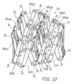
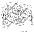
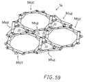
- the structure 14 having the above construction is developed, by applying an external force thereto (either vertical compressive force or lateral tensile force) in the direction of reducing the intersection angle ⁇ in each primary constituent unit U137 or U148, such that it is two-dimensionally expanded from its form close to the most contracted form as shown in FIG. 57 through an intermediate form as shown in FIG. 58 to eventually assume the most expanded form as shown in FIG. 59.
- the structure 14 is developed to a panel-like form having a double layer structure as its intermediate form (i.e., a form as shown in FIG. 58).
- the structure 13 described above is developed to a dome-like form having a double layer structure.
- the structure 14 By applying an external force (i.e., either vertical tensile force or lateral compressive force) in the direction of increasing the intersection angle ⁇ , the structure 14 is developed from the form as shown in FIG., 59 to the form as shown in FIG. 58 and then to the form as shown in FIG. 57. Thus, it is eventually three-dimensionally contracted to the most contracted form.
- the structure 14 in this most contracted form is shown in the schematic plan view of FIG. 56.
- any of the structures 6 to 9 of the sixth to ninth embodiments comprises a plurality of secondary constituent units of type 3 or 4 coupled to one another and each constituting a solid having quadrangular base and lateral faces.
- the structure 14 of this embodiment is set apart from the structures 6 to 9 in that it is obtained by coupling together the secondary constituent units M137 of type 7 each constituting a solid having hexagonal base and lateral faces and secondary constituent units M148 of type 8 each constituting a solid having triangular base and lateral faces.
- the secondary constituent unit M137 of type 7 is one version of the secondary constituent unit of type 4, and the secondary constituent unit M148 of type 8 is one version of the secondary constituent unit of type 3. Consequently, the secondary constituent units of types 3 and 4 are coupled together without regard to the shapes of the base and top of the units, and can provide a double layer structure as a result of their development.
- the structures 6 to 9 as well as the structure 14 of this embodiment are developed into forms, which are determined by the arrangement of the division ratios ⁇ of the primary constituent units U. Specifically, the structure is developed into a panel-like form (i.e., in a direction of plane or two-dimensionally) in a direction in which like division ratios ⁇ are provided, but the large and the small parts thereof are disposed in the reverse orientation, alternately. The structure is developed into a curved form (i.e., three-dimensionally) in a direction in which like division ratios ⁇ are provided, but the large and the small parts thereof are disposed in the same orientation. As an example, with the structure 9 shown in FIG.
- the lateral faces provide division ratios ⁇ of 2 : 3 vertically in the same orientation in the transversal direction.
- the structure is thus developed into a curved form.
- a division ratio ⁇ of 2 : 1 and the inverse thereof are provided alternately.
- the structure is thus developed into a panel-like form. Consequently, the structure is developed as a whole into a vault-like form.
- lateral faces provide alternate division ratios of 2 : 1 and 1 : 1 in the transversal direction.
- the structure is thus developed into a curved form.
- a division ratio of 2 : 1 and the inverse thereof are provided vertically alternately.
- the structure is thus developed into a panel-like form.
- the structure is thus developed into a vault-like form.
- the large and the small parts of the division ratios are disposed in the reverse orientation vertically alternately in both the transversal and longitudinal directions.
- the structure 6 thus undergoes linear development in both the directions, and is thus developed into a panel-like form.
- the structure 14 of this embodiment has been described in relation to one for development into a panel-like form, it is possible to provide a structure for development into a vault-like form or dome-like form by suitably selecting the division ratio ⁇ provided by each primary constituent unit U. It is also possible to combine the structure 14 of this embodiment and the structure 13 of the 13th embodiment to obtain structures with greater division numbers for development into a dome-like form having double layer structures.
- While the structure 14 shown in FIGS. 56 to 59 comprises four secondary constituent units M148 of type 8 and three secondary constituent units M137 of type 7, it is of course possible to obtain double layer structures of greater size by coupling together greater numbers of secondary constituent units M137 and M148 of types 7 and 8.
- a structure 15 of this embodiment comprises five secondary constituent units M153 of type 3 (i.e., structures 2 of the second embodiment) in which the top and base are quadrangular.
- these secondary constituent units M153 four units M153(b) to M153(e) are coupled to the respective lateral face of the remaining unit M153(a) with a primary constituent unit U153 used in common between each of them and the unit M153(a), and also they are each coupled to each adjacent secondary constituent unit M153 with a primary constituent unit U153 used in common between the two units.
- the top and base of the secondary constituent units M153(a) to M153(e) are thus rhombic (possibly parallelogrammic).
- the structure 15 of this embodiment comprises the five secondary constituent units M153 of type 3 having the rhombic top and base and coupled to one another in a direction perpendicular to their axes L with primary constituent units U153 each used in common between adjacent units.
- the large and the small parts of the division ratio ⁇ in the primary constituent units U153 are all disposed in the same orientation.
- the coupling between adjacent ones of the secondary constituent units M153 is made by using a coupler J5 of type 5 or a coupler J3 of type 3.
- the coupler J5 of type 5 is used at each locality indicated by a triangle mark in FIG. 60, and the coupler J3 of type 3 is used at a locality indicated by a circle mark.
- the structure 15 When an external force is applied to the structure 15 having the above construction in a direction of reducing the diagonal intersection angle ⁇ of each primary constituent unit U153, the structure 15 is developed from a form close to the most contracted form as shown in FIG. 61 to be brought to an intermediate form as shown in FIG. 62 and eventually expanded to the most expanded form as shown in FIG. 63(A).
- the structure 15 In its most expanded form, the structure 15 constitutes a solid (a four-dimensional solid) as shown in FIG. 63(B) in which six quadrangular pyramid frustum structures (i.e., structures 2 of the second embodiment) are oriented toward the center of a cube.
- a 16th embodiment will now be described with reference to FIGS. 64 to 67.
- a structure 16 of this embodiment is a development of the structure 15 of the 15th embodiment.
- the structure 16 comprises ten secondary constituent units M163 having rhombic base and top and coupled to one another.
- Five central secondary constituent units M163(a) each have four lateral faces coupled to other secondary constituent units M163.
- Five edge part secondary constituent units M163(b) have two lateral faces coupled to other secondary constituent units M163.
- the secondary constituent units M163 are each based on the secondary constituent unit of type 3 (i.e., structure 2 of the second embodiment) having quadrangular base and top.
- a coupler J10 of type 10 is used to couple five secondary constituent units M163 to one another.
- the coupler J10 of type 10 includes five coupling members coupled together for relative rotation about a second rotation axis P2.
- An end of a diagonal member u is coupled to each coupling member for rotation about a third rotation axis P3.
- couplers J1, J3 and J5 of types 1, 3 and 5 are used.
- the structure 16 of this embodiment When an external force is applied to the structure 16 of this embodiment in a direction of reducing the diagonal intersection angle ⁇ of each primary constituent unit U, the structure is expanded from a form close to the most contracted form as shown in FIG. 65 to be brought to an intermediate form as shown in FIG. 66 and eventually to a form close to the most expanded form as shown in FIG. 67.
- the structure 16 When it is expanded to the most expanded form, the structure 16 is like a sphere corresponding to a regular 20-face solid. Further, in the same stage, before reaching the most expanded form, it forms a dome-like structure corresponding to a half of a rhombic 30-face solid.
- a structure 17 of this embodiment is a modification of the structure 7 of the seventh embodiment (see FIGS. 26 to 28).
- the structure 17 comprises four secondary constituent units M174 coupled to one another into the form of letter T in plan view with a primary constituent unit U174 used in common between adjacent ones of them.
- Each of the secondary constituent units M174 is a modification of the secondary constituent unit of type 4 noted above and based on a solid having quadrangular base and top.
- the secondary constituent unit M174 comprises four primary constituent units U174 coupled to one another such that the large and the small parts of the division ratios ⁇ are disposed in the reverse orientation vertically alternately.
- the structure 17 can be basically developed into an arch-like form.
- the structure 17 is developed to an intermediate form as shown in FIG., 69 and eventually to a form as shown in FIG. 70.
- the secondary constituent units M174(b) and M174(c) which are coupled to the opposite sides of the central secondary constituent unit M174(a), are developed in a downwardly folded fashion, while the secondary constituent unit M174(d) coupled to the rear of the central secondary constituent unit M174(a) is developed in an upwardly folded fashion.
- the structure 17 is developed into a form like a chair as shown in FIG. 70.
- the structure 17 can be used as a chair by providing a seat material S serving as a seat over the top of the central secondary constituent unit M174(a).
- the rear secondary constituent unit M174(d) serves as a back support, and the opposite side secondary constituent units M174(b) and M174(c) serve as legs.
- the 18th embodiment is an example of the invention as set forth in claim 24, and is a development of the structure 17 of the 17th embodiment.
- the structure 18 of this embodiment comprises a plurality of (i.e., five in this embodiment) double-layer structures capable of being spread to a plate-like form, for instance, the structures 6 described before in connection with the sixth embodiment, each as a secondary constituent unit M189 of type 9.
- the secondary constituent units M189 are coupled to one another with a primary constituent unit U189 used in common between adjacent ones of them.
- each secondary constituent unit M189 is developed to a plate-like form.
- the structure 18 is thus developed to the form of a solid as shown in FIG. 72, each or some of whose faces are constituted by the plate-like double-layer structures, i.e., the secondary constituent units M189 of type 9.
- the chair-like form of the structure 18 shown in FIG. 72 corresponds to like developed form of the 17th embodiment.
- the structure 18 has each solid face constituted by a double-layer structure (i.e., secondary constituent unit M189 of type 9), so that it has higher rigidity.
- the five secondary constituent units M189 in this structure are designated by M189(a) to M189(e), respectively.
- the unit it M189(a) corresponds to a seat face
- the unit M189(b) to a back support
- the units M189(c) and M189(d) to legs
- the unit M189(e) to a lower front.
- the unit M189(b) as the back support has to extend upright with respect to the unit M189(a) as the seat face
- the unit M189(e) as the lower front has to extend downward from the unit M189(a).
- the secondary constituent unit M189(a) thus has to have an even number of primary constituent units coupled to one another in longitudinal directions (i.e., directions A in the drawing).
- each primary constituent unit M189(a) has to have an odd number of primary constituent units coupled to one another in transversal directions (i.e., directions B in the drawing).
- the division ratio ⁇ in each primary constituent unit in the structure 6 of type 6 is not 1 : 1, that is, the lateral face as the basis of each primary constituent unit is a trapezoid. It will thus be seen that where each lateral face of a polyhedron is constituted by a double layer structure, each structure generally has to have an odd number of transversally arranged primary constituent units.
- the framework structure according to the invention is a three-dimensional development of the prior art structures (e) and (f) capable of being expanded and contracted as described before.
- the invention can overcome the drawbacks inherent in the prior art structures other than those utilizing fluid that they are weak to forces exerted thereto from different planes, and that an arrangement for providing reinforced rigidity in an out-of-plane direction can not be folded in that direction, so that it is impossible to satisfy both the rigidity or mechanical strength and the degree of freedom of expansion and contraction.
- the framework structure according to the invention can be expanded two-dimensionally or three-dimensionally from a uni-dimensional form and contracted conversely.
- tension elements or compressive elements it is possible to provide high mechanical strength as a three-dimensional torus framework structure having high degree of freedom of development.
- basic structural units it is possible to provide a framework structure which can be developed uni-dimensionally or two-dimensionally to a tower-like, a vault-like or a dome-like form without loss of rigidity in intermediate forms.
- the second rotation axis P2 has been described as being coincident with the intersection between adjacent lateral faces of the solid constituted by the structure.
- the second rotation axis P2 may not be coincident with the intersection.
- a usual hinge H as shown in FIG. 73 may be used as a coupler J.
- the coupler J5 of type 5 can be obtained by combining two hinges H.
- the rotation centers C of the two hinges H are not coincident, and therefore, actually two second rotation axes P2 are provided. That is, no second rotation axis P2 is coincident with the intersection of two adjacent lateral faces.
- two second rotation axes P2 are present between adjacent primary constituent units U1 and U3. Even in this case, the adjacent primary constituent units P1 and P3 can be rotated relatively about either one or both of the second rotation axes P2.
- the structure thus can be two-dimensionally expanded and uni-dimensionally contracted without any trouble.
- the couplers J1 and J2 of types 1 and 2 may each be constituted by a single hinge. In these cases, it is possible to provide a second rotation axis P2 coincident with the intersection between adjacent lateral faces. It is thus possible to provide a structure which conforms to the theory described above. In the cases where the other couplers J3, J4 and J6 to J8 are each constituted by a plurality of hinges H, the theory is the same as with the coupler J3, and the structure can be expanded and contracted as described above.
- tension elements are used in the following embodiments.
- FIGS. 48(A) and 48(B) show embodiments which are examples of the invention as set forth in claim 25.
- tension elements such as wires
- tension elements are provided between ends of adjacent diagonal members u at localities indicated by triangle marks and/or circle marks.
- These structures can be secured in their desired forms between their most expanded form and most contracted form such that they are rigid with respect to external forces exerted thereto, such as gravitational force (or their own weight).
- the tension elements may not be provided at all the pairs of ends of adjacent diagonal members u, but tension elements having necessary mechanical strength may be provided at localities such as to provide necessary and sufficient rigidity with respect to the weight of the structure or external forces exerted thereto.
- FIG. 74 shows an example of the invention as set forth in claim 26.
- a wire C is provided for a structure constituting a quadrangular prism, i.e., a secondary constituent unit of type 2 (see FIG. 43).
- FIG. 76 the structure itself is not shown, but only the route which the wire C is passed along is shown schematically.
- the wire C is passed around eight corners 0 to 7 of the quadrangular prism structure along the route of "0 ⁇ 3 ⁇ 5 ⁇ 6 ⁇ 7 ⁇ 4 ⁇ 2 ⁇ 1 ⁇ 0".
- a wire passing member as shown in FIG. 76 is provided.
- the illustrated wire passing member is a pulley W which is supported via a ring-like rail R secured to an end of the diagonal member u.
- the diagonal member u is made from a pipe. Each end of the pipe is cut obliquely.
- the wire C is led through the pipe and out of each end thereof to be passed around the pulley W.
- the pulley W is rotatable and is also movable along the rail R.
- the wire C is passed along the route noted above past the pulleys W provided as the wire passing members at the corners 0 to 7. Its trailing ends CE is directly secured at the corner 0 to the end of the diagonal member u or to the wire passing member.
- the structure can be folded by pulling the wire C.
- the structure By securing the leading end CS of the wire C against returning after bringing the structure to a desired form by pulling the wire C to a predetermined extent, the structure can be secured in the desired form such that it is rigid with respect to vertically exerted external forces such as its own weight.
- FIG. 75 shows another example in which a wire C is passed along a different route.
- the wire C is passed around eight corners 0 to 7 of a solid (i.e., a quadrangular prism) constituting the structure along a route "0 ⁇ 5 ⁇ 1 ⁇ 7 ⁇ 3 ⁇ 6 ⁇ 2 ⁇ 4 ⁇ 0".
- the trailing end CE of the wire C is secured to the end of the diagonal member u or a wire passing member at the corner 0.
- a pulley W is supported in the manner as described above on a wire passing member at each of the corners 0 to 7.
- the diagonal members u in each primary constituent unit U are rotated relatively in a direction of reducing their intersection angle ⁇ .
- the structure is thus expanded two-dimensionally toward the most expanded form.
- the structure can be secured in a desired form.
- the structure thus is now rigid with respect to vertically exerted tensile forces or transversely exerted compressive forces. This wire passing route is thus effective when the transversal directions are gravitational directions.
- the structure can be changed to a desired form by pulling the leading end CS of the wire C to a predetermined extent.
- the structure can be secured to be in a form which is rigid with respect to externally exerted forces.
- pulleys W are used as the wire passing members in the above embodiments, this is by no means limitative; for example, it is possible to pass the wire C directly round the ring-like rails R noted above.
- the most basic structures have been described for the brevity of the description, this is by no means limitative, and the invention is applicable as well to various complicated structures as described above, in which basic structures are coupled together as secondary constituent units in their axial direction and/or a direction perpendicular thereto.
- a single wire C is used in the above embodiments, this is by no means limitative, and it is possible to pass a suitable number of wires C in a sharing fashion along the overall route.
- this embodiment is a combination of the embodiments described above in connection with FIGS. 74 and 75.
- two wires C are passed along the routes described before with reference to FIGS. 74 and 75, respectively.
- the diagonal members u in each primary constituent unit U are rotated relatively in a direction of increasing their intersection angle ⁇ .
- the structure is thus contracted toward the most contracted form.
- the diagonal members u in each primary constituent unit U conversely rotated relatively in a direction of reducing their intersection angle ⁇ .
- the structure is thus expanded toward the most expanded form.
- the structure is contracted by pulling one of these wires C and expanded by pulling the other wire C, so that it can be readily changed in its contracted form (or expanded form).
- the structure may further be made rigid against external force exerted in every direction by securing the two wires C against returning after pulling these wires to predetermined extents. This means that it is possible to obtain the same status as obtainable by providing tension elements at localities indicated by circle marks and triangle marks in FIGS. 48(A) and 48(B).
- a wire for expanding the structure and a wire for contracting the same are passed around each corner.
- a wire passing member for passing a plurality of wires C may be constructed by mounting a necessary number of pulleys W on a rail R. It is further possible to mount the necessary number of wires C directly on the rail R instead of pulleys W. In either case, the necessary number of wires C may be passed through the pipes as diagonal members u.
- each diagonal member u in each primary constituent unit U is a pipe as described before in connection with FIG. 76, and wires C are passed through pipes.
- This arrangement provides a structure having neat appearance and prevents such trouble as catching of wires C at other localities of the structure than those where the wires C are passed, thus providing enhanced reliability of motion and durability.
- the pulleys W as the wire passing members are provided at the ends of the diagonal members u, it is also possible to provide wire passing members on couplers J.
- the invention provides a structure changeable in form which is constructed in consideration of the diagonals of lateral faces of a solid.
- the structure can be developed from a plate-like or mass-like highly densely contracted form to a tower-like form in the former case or a plate-like or polyhedral form in the latter case without spoiling its rigidity as a solid framework in its intermediate stages of development. It is thus possible to readily obtain high building structures, space structures and various other structures.
- the structure comprises a plurality of primary constituent units, which each have isosceles trapezoidal lateral faces with diagonals thereof constituted by diagonal members coupled together for relative rotation at the intersection thereof, and which are coupled to one another at the apices of the solid via couplers having three or more rotation axes into a ring-like form.
- the structure constitutes a pyramid frustum only with congruent isosceles trapezoidal lateral faces, it can be changed in form from a two-dimensional form (most expanded form) through an intermediate solid form to a uni-dimensional form (most contracted form).
- the first embodiment concerns a triangular pyramid frustum
- the second embodiment concerns a quadrangular pyramid frustum. Similar changes in form are obtainable in cases where other faces than isosceles trapezoids are involved.
- the third to fifth embodiments illustrate that it is possible to obtain multiple layer structures while using in common the second and the third rotation axes P2 and P3 of the couplers J.
- similar pyramid frustums with a geometrical series of primary constituent unit division ratios ⁇ successively appear infinitely in a finite space.
- Solids with six base corners may be combined with triangular pyramid frustums to fill space.
- Either of these patterns is obtained by taking out the diagonals of trapezoidal faces obtained by slicing a three-dimensional torus which fills space with regular tetrahedrons and regular octahedrons, along two parallel planes which are parallel to a rectangular face in the former pattern and to a triangular face in the latter one. It is further possible to obtain a form change from a folded form to a form having a vault-like or wavy curved configuration by providing different primary constituent unit division ratios ⁇ of adjacent secondary constituent units. This is exemplified in the seventh to ninth embodiments.
- the structures can be developed without spoiling rigidity in their intermediate stages of development and form a three-dimensional torus by providing action of tension elements.
- the structures are thus applicable to foundations, space structures, etc.
- the structure 15 of the 15th embodiment when developed, constitutes a solid in which six quadrangular pyramid frustum structures (i.e., structures 2 of the second embodiment) are oriented toward the center of a cube. This is thought to be obtained by applying the structure 2 to three-dimensional center projection of a four-dimensional cube (i.e., regular octatope). This structure is thought to undergo form change as 3-D ⁇ 4-D ⁇ 1-D in four-dimensional space. While the structure is stable in three-dimensional space, its form changes in three-dimensional space may be realized by developing a polytope.
- the 13th, 16th, 17th and 18th embodiments as well as the 15th embodiment concern double layer polyhedrons.
- a different process of three-dimensional development of a four-dimensional prism is the case with a star-like solid which comprises a plurality of basic structures (for instance, structures of the first or the second embodiment) each disposed on each face of a polyhedron.
- the structure 11 of the 11th embodiment is an example of this structure.
- a star-like structure with five tower-like projections can be changed in form to a single layer dome. It is possible to increase the number of tower-like projections, and this process can be utilized as a new process of constructing dome-like structures.
Landscapes
- Engineering & Computer Science (AREA)
- Architecture (AREA)
- Civil Engineering (AREA)
- Structural Engineering (AREA)
- Physics & Mathematics (AREA)
- Electromagnetism (AREA)
- Toys (AREA)
- Joining Of Building Structures In Genera (AREA)
- Rod-Shaped Construction Members (AREA)
Claims (28)
- Structure formant ossature, comportant une pluralité d'unités constituantes principales (U), chacune comportant deux éléments diagonaux rigides (u) qui constituent les diagonales d'une face latérale quadrangulaire d'un solide, les côtés d'au moins l'une de deux paires de côtés opposés de la face latérale quadrangulaire étant parallèles, les deux éléments diagonaux (u) étant accouplés ensemble pour une rotation relative autour d'un premier axe de rotation (P1), les unités constituantes principales (U) étant accouplées les unes aux autres à la manière d'un anneau en accouplant une extrémité de chaque élément diagonal (u) de chaque unité constituante principale (U) par l'intermédiaire d'un dispositif d'accouplement (J) à une extrémité associée d'un élément diagonal d'une unité constituante principale adjacente, le dispositif d'accouplement (J) ayant une pluralité d'éléments d'accouplement (Ja), une extrémité d'un des éléments diagonaux étant accouplée à chacun des éléments d'accouplement (Ja) pour une rotation autour d'un troisième axe de rotation (P3) parallèle au premier axe de rotation (P1), caractérisée en ce que les éléments d'accouplement sont accouplés ensemble pour une rotation mutuelle autour d'un deuxième axe de rotation (P2), des unités constituantes principales qui sont adjacentes étant ainsi accouplées ensemble pour une rotation relative autour du deuxième axe de rotation (P2), et le premier axe de rotation (P1) passe à travers l'intersection des diagonales des éléments diagonaux (u).
- Structure formant ossature selon la revendication 1, dans laquelle chacune des unités constituantes principales (U) comporte deux éléments diagonaux (u) qui constituent les diagonales d'une face latérale carrée ou rectangulaire d'un solide, et dans laquelle le premier axe de rotation (P1) de chaque unité constituante principale (U) divise le segment de chacun de ses éléments diagonaux (u) entre les deux troisièmes axes de rotation (P3) dans un rapport de 1:1.
- Structure formant ossature selon la revendication 1, dans laquelle chacune des unités constituantes principales (U) comporte deux éléments diagonaux (u) qui constituent les diagonales d'une face latérale trapézoïdale isocèle d'un solide, et dans laquelle le premier axe de rotation (P1) de chaque unité constituante principale (U) divise le segment de chacun de ses éléments diagonaux (u) entre les deux troisièmes axes de rotation (P3) selon un rapport égal, les parties grande et petite du rapport de division étant disposées dans la même orientation.
- Structure formant ossature selon la revendication 1, dans laquelle chacune des unités constituantes principales (U) comporte deux éléments diagonaux (u) qui constituent les diagonales d'une face latérale trapézoïdale isocèle d'un solide, et dans laquelle le premier axe de rotation (P1) de chaque unité constituante principale (U) divise le segment de chacun de ses éléments diagonaux (u) entre les deux troisièmes axes de rotation (P3) selon un rapport égal, les parties grande et petite du rapport de division étant disposées dans l'orientation inverse, de manière alternée.
- Structure formant ossature selon la revendication 1, dans laquelle chacune des unités constituantes principales (U) comporte deux éléments diagonaux (u) qui constituent les diagonales d'une face latérale trapézoïdale isocèle d'un solide, et dans laquelle le premier axe de rotation (P1) de chaque unité constituante principale (U) divise le segment de chacun de ses éléments diagonaux (u) entre les deux troisièmes axes de rotation (P3) selon deux rapports différents, les unités constituantes principales (U) ayant les deux rapports de division différents étant accouplées ensemble de manière alternée.
- Structure formant ossature comportant une pluralité d'unités constituantes secondaires, chacune constituée par la structure formant ossature selon la revendication 2, les unités constituantes secondaires étant accouplées les unes aux autres dans la direction d'un axe passant à travers leur centre à l'aide de dispositifs d'accouplements (J) utilisés en commun entre des unités constituantes secondaires qui sont adjacentes.
- Structure formant ossature comportant une pluralité d'unités constituantes secondaires, chacune constituée par la structure formant ossature selon la revendication 3, les unités constituantes secondaires (M31, M32, M33 ; M41, M42, M43) étant accouplées les unes aux autres dans la direction d'un axe passant à travers leur centre à l'aide de dispositifs d'accouplements (J1, J2) utilisés en commun entre des unités constituantes secondaires (M31, M32, M33 ; M41, M42, M43) qui sont adjacentes.
- Structure formant ossature comportant une pluralité d'unités constituantes secondaires, chacune constituée par la structure formant ossature selon la revendication 4, les unités constituantes secondaires étant accouplées les unes aux autres dans la direction d'un axe passant à travers leur centre à l'aide de dispositifs d'accouplements (J) utilisés en commun entre des unités constituantes secondaires qui sont adjacentes.
- Structure formant ossature comportant une pluralité d'unités constituantes secondaires, chacune constituée par la structure formant ossature selon la revendication 5, les unités constituantes secondaires étant accouplées les unes aux autres dans la direction d'un axe passant à travers leur centre à l'aide de dispositifs d'accouplements (J) utilisés en commun entre des unités constituantes secondaires qui sont adjacentes.
- Structure formant ossature comportant une pluralité d'unités constituantes secondaires, chacune constituée par la structure formant ossature selon la revendication 2, les unités constituantes secondaires étant accouplées les unes aux autres dans la direction perpendiculaire à un axe passant à travers leur centre à l'aide d'une unité constituante principale (U) utilisée en commun entre des unités constituantes secondaires qui sont adjacentes.
- Structure formant ossature comportant une pluralité d'unités constituantes secondaires, chacune constituée par la structure formant ossature selon la revendication 3, les unités constituantes secondaires (M153) étant accouplées les unes aux autres dans la direction perpendiculaire à un axe passant à travers leur centre à l'aide d'une unité constituante principale (U) utilisée en commun entre des unités constituantes secondaires (M153) qui sont adjacentes.
- Structure formant ossature comportant une pluralité d'unités constituantes secondaires, chacune constituée par la structure formant ossature selon la revendication 4, les unités constituantes secondaires étant accouplées les unes aux autres dans la direction perpendiculaire à un axe passant à travers leur centre à l'aide d'une unité constituante principale (U) utilisée en commun entre des unités constituantes secondaires qui sont adjacentes.
- Structure formant ossature comportant une pluralité d'unités constituantes secondaires, chacune constituée par la structure formant ossature selon la revendication 5, les unités constituantes secondaires étant accouplées les unes aux autres dans la direction perpendiculaire à un axe passant à travers leur centre à l'aide d'une unité constituante principale (U) utilisée en commun entre des unités constituantes secondaires qui sont adjacentes.
- Structure formant ossature comportant une pluralité d'unités constituantes secondaires, chacune constituée par la structure formant ossature selon la revendication 2, des unités constituantes secondaires qui sont adjacentes étant accouplées ensemble, à l'aide de dispositifs d'accouplements (J) utilisés en commun, dans la direction d'un axe passant à travers leur centre, et des unités constituantes secondaires qui sont adjacentes étant accouplées ensemble, à l'aide d'une unité constituante principale (U) utilisée en commun, dans la direction perpendiculaire à un axe passant à travers leur centre.
- Structure formant ossature comportant une pluralité d'unités constituantes secondaires, chacune constituée par une structure formant ossature selon la revendication 3, des unités constituantes secondaires (M31, M32, M33) qui sont adjacentes étant accouplées ensemble, à l'aide de dispositifs d'accouplements (J1, J2, J3) utilisés en commun, dans la direction d'un axe passant à travers leur centre, et des unités constituantes secondaires (M31, M32, M33) qui sont adjacentes étant accouplées ensemble, à l'aide d'une unité constituante principale (U) utilisée en commun, dans la direction perpendiculaire à un axe passant à travers leur centre.
- Structure formant ossature comportant une pluralité d'unités constituantes secondaires, chacune constituée par une structure formant ossature selon la revendication 4, des unités constituantes secondaires qui sont adjacentes étant accouplées ensemble, à l'aide de dispositifs d'accouplements (J) utilisés en commun, dans la direction d'un axe passant à travers leur centre, et des unités constituantes secondaires qui sont adjacentes étant accouplées ensemble, à l'aide d'une unité constituante principale (U) utilisée en commun, dans la direction perpendiculaire à un axe passant à travers leur centre.
- Structure formant ossature comportant une pluralité d'unités constituantes secondaires, chacune constituée par une structure formant ossature selon la revendication 5, des unités constituantes secondaires qui sont adjacentes étant accouplées, à l'aide de dispositifs d'accouplements utilisés en commun, dans la direction d'un axe passant à travers leur centre, et des unités constituantes secondaires qui sont adjacentes étant accouplées ensemble, à l'aide d'une unité constituante principale (U) utilisée en commun, dans la direction perpendiculaire à un axe passant à travers leur centre.
- Structure formant ossature comportant quatre types différents d'unités constituantes secondaires constituées par des structures formant ossature respectives selon les revendications 2 à 5, les unités constituantes secondaires d'un type sélectionné parmi les quatre différents types étant accouplées les unes aux autres dans la direction d'un axe passant à travers leur centre à l'aide de dispositifs d'accouplements (J) utilisés en commun entre des unités constituantes secondaires qui sont adjacentes.
- Structure formant ossature comportant quatre types différents d'unités constituantes secondaires constituées par des structures formant ossature respectives selon les revendications 2 à 5, les unités constituantes secondaires (M61, M62 ; M71, M72 ; M91, M92 ; M136, M137) d'une pluralité de types sélectionnés parmi les quatre différents types étant accouplées les unes aux autres dans la direction perpendiculaire à un axe passant à travers leur centre à l'aide d'une unité constituante principale (U) utilisée en commun entre des unités constituantes secondaires (M61, M62 ; M71, M72 ; M91, M92 ; M136, M137) qui sont adjacentes.
- Structure formant ossature comportant quatre types différents d'unités constituantes secondaires constituées par les structures formant ossature respectives selon les revendications 2 à 5, les unités constituantes secondaires d'une pluralité de types sélectionnés parmi les quatre différents types étant accouplées les unes aux autres dans la direction d'un axe passant à travers leur centre, et dans la direction perpendiculaire à un axe passant à travers leur centre à l'aide de dispositifs d'accouplement (J) ou d'une unité constituante principale utilisés en commun entre des unités constituantes secondaires qui sont adjacentes.
- Structure formant ossature comportant quatre types différents d'unités constituantes secondaires (M101, M102, M103) constituées par les structures formant ossature respectives selon les revendications 2 à 5, des unités constituantes secondaires (M101, M102, M103) qui sont adjacentes, d'un type sélectionné ou d'une pluralité de types sélectionnés parmi les quatre types différents étant accouplées ensemble via une paire de dispositifs d'accouplement (J6) accouplés ensemble pour une rotation relative autour d'un quatrième axe de rotation (P4) perpendiculaire aux deuxièmes axes de rotation (P2) de la paire de dispositifs d'accouplement, des unités constituantes principales adjacentes (U101, U102, U103) étant disposées entre les deux unités constituantes secondaires adjacentes (M101, M102, M103) et accouplées ensemble pour une rotation relative autour du quatrième axe de rotation (P4).
- Structure formant ossature comportant un polyèdre, toutes ses faces latérales ou certaines de celles-ci étant chacune constituée par la structure formant ossature selon la revendication 1, les structures formant ossature étant disposées avec leurs bases alignées les unes avec les autres, des structures formant ossature qui sont adjacentes étant accouplées ensemble via des dispositifs d'accouplement adjacents (J7, J8) accouplés ensemble pour une rotation relative autour d'un cinquième axe de rotation (P5).
- Structure formant ossature comportant une pluralité d'unités constituantes principales (U120), chacune comportant deux éléments diagonaux rigides (u) qui constituent les diagonales d'une face latérale quadrangulaire d'un solide, la face latérale quadrangulaire ayant les côtés d'au moins une paire parmi deux paires de côtés opposés se trouvant dans des plans parallèles, les deux éléments diagonaux (u) étant accouplés ensemble pour une rotation relative autour d'un premier axe de rotation (P1), les unités constituantes principales (U120) étant accouplées les unes aux autres à la manière d'un anneau en accouplant une extrémité de chaque élément diagonal (u) de chaque unité constituante principale (U120) par l'intermédiaire d'un dispositif d'accouplement (J9) à une extrémité associée d'un élément diagonal (u) d'une unité constituante principale adjacente (U120), caractérisée en ce que certains des dispositifs d'accouplement (J9) comportent chacun un premier élément d'accouplement (J91) accouplé à l'élément diagonal associé (u) pour une rotation relative autour d'un septième axe de rotation (P7) s'étendant dans la direction axiale de l'élément diagonal associé (u), et un second élément d'accouplement (J91) accouplé au premier élément d'accouplement (J91) pour une rotation autour d'un sixième axe de rotation (P6) perpendiculaire au septième axe de rotation (P7), et le premier axe de rotation (P1) passant à travers l'intersection des diagonales des éléments diagonaux (u).
- Structure formant ossature comportant une pluralité d'unités constituantes secondaires (M189) de type 9, chacune constituée par la structure formant ossature selon la revendication 19, les unités constituantes secondaires (M189) étant accouplées ensemble à l'aide d'une pluralité d'unités constituantes principales (U) utilisées en commun entre des unités adjacentes parmi celles-ci, les unités constituantes secondaires (M189) étant chacune disposée sur chaque face latérale, ou sur certaines faces latérales d'un polyèdre dans une forme développée de la structure formant ossature.
- Structure formant ossature selon l'une quelconque des revendications 1 à 24, dans laquelle un élément de tension est passé entre des extrémités appariées des deux éléments diagonaux (u) de chaque unité constituante principale (U), de manière à empêcher une rotation relative des deux éléments diagonaux lorsqu'une force extérieure est exercée sur la structure, en rendant ainsi la structure rigide.
- Structure formant ossature selon l'une quelconque des revendications 1 à 24, dans laquelle un fil (C) est passé en tant qu'élément de tension autour d'éléments de passage de fil (W) agencés sur des extrémités appariées des deux éléments diagonaux (u) d'une unité constituante principale (U), ou sur deux éléments d'accouplement, le fil (C) pouvant être fixé au niveau de son extrémité de queue (Ce) sur un élément diagonal (u) ou sur un élément d'accouplement (Ja), tandis que son extrémité de tête (Cs) est fixée dans un état tiré pour empêcher une rotation relative des deux éléments diagonaux (u) ou des éléments d'accouplement lorsqu'une force extérieure est exercée sur la structure, en rendant ainsi la structure rigide.
- Structure formant ossature selon l'une quelconque des revendications 1 à 24, dans laquelle au moins deux fils (C) sont passés en tant qu'éléments de tension autour d'éléments de passage de fil (W) agencés sur des extrémités appariées des deux éléments diagonaux d'une unité constituante principale (U), ou sur deux dispositifs d'accouplement, de telle sorte qu'un des fils (C) est mené le long d'un trajet pour s'agrandir et que l'autre des fils métalliques (C) est mené le long d'un trajet pour se raccourcir, la structure étant agrandie dans une forme en deux dimensions en tirant le fil mené le long du trajet pour s'agrandir, la structure étant raccourcie dans une forme à une seule dimension en tirant le fil métallique mené le long du trajet pour se raccourcir.
- Structure formant ossature selon la revendication 26 ou 27, dans laquelle les éléments diagonaux (u) de chaque unité constituante principale (U) sont constitués de tuyaux, le fil ou les fils (C) étant menés à travers les tuyaux.
Applications Claiming Priority (4)
| Application Number | Priority Date | Filing Date | Title |
|---|---|---|---|
| PCT/JP1994/000184 WO1995021350A1 (fr) | 1994-02-07 | 1994-02-07 | Construction a cadre |
| JP184/94 | 1994-02-07 | ||
| WOPCT/JP94/00184 | 1994-02-07 | ||
| PCT/JP1994/001498 WO1995021351A1 (fr) | 1994-02-07 | 1994-09-09 | Structure |
Publications (3)
| Publication Number | Publication Date |
|---|---|
| EP0744575A1 EP0744575A1 (fr) | 1996-11-27 |
| EP0744575A4 EP0744575A4 (fr) | 1998-04-01 |
| EP0744575B1 true EP0744575B1 (fr) | 2001-07-04 |
Family
ID=14098173
Family Applications (1)
| Application Number | Title | Priority Date | Filing Date |
|---|---|---|---|
| EP94926382A Expired - Lifetime EP0744575B1 (fr) | 1994-02-07 | 1994-09-09 | Structure |
Country Status (7)
| Country | Link |
|---|---|
| US (1) | US5761871A (fr) |
| EP (1) | EP0744575B1 (fr) |
| JP (1) | JP3455221B2 (fr) |
| AU (2) | AU5979994A (fr) |
| CA (1) | CA2182789C (fr) |
| DE (1) | DE69427652T2 (fr) |
| WO (2) | WO1995021350A1 (fr) |
Cited By (1)
| Publication number | Priority date | Publication date | Assignee | Title |
|---|---|---|---|---|
| CN111926921A (zh) * | 2020-08-12 | 2020-11-13 | 长沙理工大学 | 一种可展单元构成的圆柱面机构 |
Families Citing this family (29)
| Publication number | Priority date | Publication date | Assignee | Title |
|---|---|---|---|---|
| WO2000012832A2 (fr) * | 1998-08-26 | 2000-03-09 | Molecular Geodesics, Inc. | Dispositif extensible radialement |
| US6082056A (en) * | 1998-09-16 | 2000-07-04 | Hoberman; Charles | Reversibly expandable structures having polygon links |
| US6219974B1 (en) * | 1998-09-16 | 2001-04-24 | Charles Hoberman | Reversibly expandable structures having polygon links |
| FR2791117B1 (fr) * | 1999-03-17 | 2001-05-11 | Jean Francois Verney | Element de construction |
| WO2002063111A1 (fr) * | 2001-02-07 | 2002-08-15 | Charles Hoberman | Ensembles circulaires pourvus d'un maillon central |
| US7028442B2 (en) | 2001-07-03 | 2006-04-18 | Merrifield Donald V | Deployable truss beam with orthogonally-hinged folding diagonals |
| WO2003054318A2 (fr) * | 2001-11-26 | 2003-07-03 | Charles Hoberman | Panneaux pliables de revetement pour structures extensibles |
| GB0229599D0 (en) * | 2002-12-19 | 2003-01-22 | Isis Innovation | Deployable structure |
| EP1678997B1 (fr) * | 2003-10-28 | 2008-02-27 | Gosei Nakagawa, S.A. | Serre en plastique |
| US7963084B2 (en) | 2005-08-29 | 2011-06-21 | Donald Merrifield | Deployable triangular truss beam with orthogonally-hinged folding diagonals |
| US8371087B2 (en) * | 2006-08-28 | 2013-02-12 | Studio Dror | Folding support or frame structure |
| US8291781B2 (en) * | 2007-12-21 | 2012-10-23 | Schlumberger Technology Corporation | System and methods for actuating reversibly expandable structures |
| US8886287B2 (en) * | 2008-04-14 | 2014-11-11 | Mri Robotics Llc | Tissue-stabilization device and method for medical procedures |
| IT1394107B1 (it) * | 2009-05-08 | 2012-05-25 | Grasso | Elemento strutturale per una costruzione gridshell, costruzione gridshell includente detto elemento e procedimento per realizzare tale costruzione impiegando detto elemento. |
| ES2368639B1 (es) * | 2009-08-21 | 2012-10-02 | Rodrigo García González | Sistema estructural desplegable fractal. |
| ITNA20090063A1 (it) * | 2009-10-14 | 2011-04-15 | Nicola Pelliccia | Lastra piana modulare aggregabile per la formazione di strutture autoportanti a calotta sferica |
| US20130184535A1 (en) | 2012-01-10 | 2013-07-18 | The Board Of Trustees Of The Leland Stanford Junior University | Expandable tissue retraction devices |
| US8991131B1 (en) * | 2014-01-29 | 2015-03-31 | Baojing Lu | Construction system for building curved structures |
| JP5996713B1 (ja) * | 2015-04-30 | 2016-09-21 | 株式会社不二宮製作所 | 伸縮アームを用いた面積可変枠体及び体積可変立体構造物 |
| US10123791B2 (en) * | 2015-07-02 | 2018-11-13 | Atlantic Health System, Inc. | Lighted polyhedral retractor |
| US10758218B2 (en) * | 2015-07-02 | 2020-09-01 | Atlantic Health System, Inc. | Lighted polyhedral retractor |
| US9783977B2 (en) * | 2015-11-20 | 2017-10-10 | University Of South Florida | Shape-morphing space frame apparatus using unit cell bistable elements |
| CN106931301A (zh) * | 2015-12-30 | 2017-07-07 | 佛山市禾才科技服务有限公司 | 一种三棱锥复合机构 |
| CN106931120A (zh) * | 2015-12-30 | 2017-07-07 | 佛山市禾才科技服务有限公司 | 一种四棱锥复合机构 |
| US10422124B1 (en) * | 2016-05-12 | 2019-09-24 | University Of South Florida | Bistable collapsible compliant mechanisms and shape-changing structures that comprise them |
| JP6341578B2 (ja) * | 2016-12-06 | 2018-06-13 | 株式会社不二宮製作所 | 形状可変枠体および形状可変立体構造物 |
| EP3596278B1 (fr) | 2017-03-16 | 2023-08-30 | Vrije Universiteit Brussel | Module de ciseau repliable pour grilles de ciseaux doublement incurvées |
| WO2019094502A1 (fr) | 2017-11-07 | 2019-05-16 | Prescient Surgical, Inc. | Procédés et appareil pour la prévention d'une infection de site chirurgical |
| JP6937527B1 (ja) * | 2020-05-15 | 2021-09-22 | 株式会社不二宮製作所 | 屈曲部材を備える視覚的興味刺激構造体 |
Family Cites Families (22)
| Publication number | Priority date | Publication date | Assignee | Title |
|---|---|---|---|---|
| US1546698A (en) * | 1922-05-02 | 1925-07-21 | Zoll Lowis | Folding or extension scaffold |
| IL34025A (en) * | 1970-03-08 | 1971-04-28 | Peret Co | Collapsible reticular structures |
| US3877544A (en) * | 1971-10-14 | 1975-04-15 | Del Mar Eng Lab | Stress balanced extendible boom structure |
| JPS537912A (en) * | 1976-07-09 | 1978-01-24 | Iga Kousan Kk | Expansion structure |
| JPS5318815A (en) * | 1976-08-06 | 1978-02-21 | Tokai Rubber Ind Ltd | Rubber hose for joint |
| US4126974A (en) | 1977-11-17 | 1978-11-28 | Hardin Gary L | Expandable beam structure |
| JPS5844721Y2 (ja) * | 1978-10-14 | 1983-10-11 | 孝久 島津 | 折りたたみできる簡易車庫 |
| US4253284A (en) | 1979-06-11 | 1981-03-03 | University Of Utah | Foldable and curvilinearly extensible structure |
| JPS57192700A (en) * | 1981-05-23 | 1982-11-26 | Tookiyoo Bebii Kk | Structure of frame body |
| JPS5844721A (ja) * | 1982-08-31 | 1983-03-15 | Toshiba Corp | 半導体ウエハベ−キング装置 |
| US4791761A (en) * | 1982-09-30 | 1988-12-20 | John Goudie Associates, Inc. | Lockable display frame |
| IT1162948B (it) * | 1983-09-30 | 1987-04-01 | Aeritalia Spa | Braccio estensibile particolarmente per veicoli o moduli spaziali |
| US5167100A (en) | 1986-06-12 | 1992-12-01 | Anandasivam Krishnapillai | Deployable structures |
| US5125205A (en) * | 1986-12-10 | 1992-06-30 | William John Wichman | Display frame with folding display attachment devices |
| JPS63255435A (ja) * | 1987-04-13 | 1988-10-21 | 津田 勝 | 組立ハウス |
| US4779635A (en) * | 1987-08-26 | 1988-10-25 | Lynch James P | Collapsible canopy with telescoping roof support structure |
| GB8803879D0 (en) * | 1988-02-19 | 1988-03-23 | Vinten Ltd | Improvements in/relating to height adjustable platforms |
| US4942700A (en) * | 1988-10-27 | 1990-07-24 | Charles Hoberman | Reversibly expandable doubly-curved truss structure |
| US5038532A (en) * | 1989-10-10 | 1991-08-13 | University Of New Mexico | Deployable spatial structure |
| DE69019818T2 (de) * | 1990-05-09 | 1996-02-29 | Charles Hoberman | Radiale erweiterbare-einziehbare Fachwerkträger. |
| CN1030791C (zh) * | 1991-08-09 | 1996-01-24 | 蔡明良 | 结构改良的折叠帐篷 |
| US5203134A (en) * | 1991-09-12 | 1993-04-20 | Skyline Displays, Inc. | Pivotal frame connector |
-
1994
- 1994-02-07 WO PCT/JP1994/000184 patent/WO1995021350A1/fr not_active Ceased
- 1994-02-07 AU AU59799/94A patent/AU5979994A/en not_active Abandoned
- 1994-09-09 US US08/687,323 patent/US5761871A/en not_active Expired - Lifetime
- 1994-09-09 WO PCT/JP1994/001498 patent/WO1995021351A1/fr not_active Ceased
- 1994-09-09 AU AU76242/94A patent/AU688790B2/en not_active Ceased
- 1994-09-09 JP JP52049395A patent/JP3455221B2/ja not_active Expired - Fee Related
- 1994-09-09 EP EP94926382A patent/EP0744575B1/fr not_active Expired - Lifetime
- 1994-09-09 DE DE69427652T patent/DE69427652T2/de not_active Expired - Fee Related
- 1994-09-09 CA CA002182789A patent/CA2182789C/fr not_active Expired - Fee Related
Cited By (2)
| Publication number | Priority date | Publication date | Assignee | Title |
|---|---|---|---|---|
| CN111926921A (zh) * | 2020-08-12 | 2020-11-13 | 长沙理工大学 | 一种可展单元构成的圆柱面机构 |
| CN111926921B (zh) * | 2020-08-12 | 2021-07-27 | 长沙理工大学 | 一种可展单元构成的圆柱面机构 |
Also Published As
| Publication number | Publication date |
|---|---|
| WO1995021351A1 (fr) | 1995-08-10 |
| DE69427652T2 (de) | 2002-05-08 |
| CA2182789C (fr) | 2005-08-02 |
| AU688790B2 (en) | 1998-03-19 |
| EP0744575A1 (fr) | 1996-11-27 |
| US5761871A (en) | 1998-06-09 |
| WO1995021350A1 (fr) | 1995-08-10 |
| DE69427652D1 (de) | 2001-08-09 |
| AU7624294A (en) | 1995-08-21 |
| CA2182789A1 (fr) | 1995-08-10 |
| AU5979994A (en) | 1995-08-21 |
| EP0744575A4 (fr) | 1998-04-01 |
| JP3455221B2 (ja) | 2003-10-14 |
Similar Documents
| Publication | Publication Date | Title |
|---|---|---|
| EP0744575B1 (fr) | Structure | |
| JPWO1995021351A1 (ja) | 骨組み構造体 | |
| US6929017B2 (en) | Collapsible canopy framework structure of a regular polygon | |
| CA2750824C (fr) | Abris repliables avec et sans moyeu flottant | |
| JP3062246B2 (ja) | 多面体建物システム | |
| US5274980A (en) | Polyhedron building system having telescoping scissors | |
| US4539786A (en) | Biaxial scissors fold, post tensioned structure | |
| US7481235B2 (en) | Articulating hub assembly | |
| US4689932A (en) | Portable shelter assemblies | |
| EP0305183A1 (fr) | Tente repliable ayant une structure support de toit téléscopique | |
| AU9177491A (en) | Collapsible canopy framework having captured scissor ends with non-compressive pivots | |
| WO1991005921A1 (fr) | Structure spatiale deployable | |
| Hernandez | Deployable Estructures | |
| Doroftei et al. | An overview on the applications of mechanisms in architecture. Part I: bar structures | |
| WO1997044543A1 (fr) | Structure de charpente et son procede de formation | |
| CN212435636U (zh) | 具有四边形构件的单自由度可无限扩展可展结构 | |
| CN115548622A (zh) | 基于斜五面体单元阵列式单自由度抛物柱面折展天线机构 | |
| Atake | ATAKE's structure-new variations of the scissors technique | |
| CN114865279B (zh) | 基于斜六棱柱单元的对称式双层周边桁架折展天线机构 | |
| GB2315286A (en) | Structure | |
| JPWO1995021350A1 (ja) | 骨組み構造体 | |
| GB2119825A (en) | Erecting folded-plate structure | |
| US4400926A (en) | Integrated dimorphic structure | |
| Belda | Keynote address constructive problems in the deployable structures of Emilio Perez Pinero | |
| Tuczek | Folding a dome |
Legal Events
| Date | Code | Title | Description |
|---|---|---|---|
| PUAI | Public reference made under article 153(3) epc to a published international application that has entered the european phase |
Free format text: ORIGINAL CODE: 0009012 |
|
| 17P | Request for examination filed |
Effective date: 19960812 |
|
| AK | Designated contracting states |
Kind code of ref document: A1 Designated state(s): DE DK ES FR GB IT SE |
|
| A4 | Supplementary search report drawn up and despatched |
Effective date: 19980210 |
|
| AK | Designated contracting states |
Kind code of ref document: A4 Designated state(s): DE DK ES FR GB IT SE |
|
| 17Q | First examination report despatched |
Effective date: 19990929 |
|
| GRAG | Despatch of communication of intention to grant |
Free format text: ORIGINAL CODE: EPIDOS AGRA |
|
| GRAH | Despatch of communication of intention to grant a patent |
Free format text: ORIGINAL CODE: EPIDOS IGRA |
|
| GRAH | Despatch of communication of intention to grant a patent |
Free format text: ORIGINAL CODE: EPIDOS IGRA |
|
| GRAA | (expected) grant |
Free format text: ORIGINAL CODE: 0009210 |
|
| AK | Designated contracting states |
Kind code of ref document: B1 Designated state(s): DE DK ES FR GB IT SE |
|
| REF | Corresponds to: |
Ref document number: 69427652 Country of ref document: DE Date of ref document: 20010809 |
|
| ITF | It: translation for a ep patent filed | ||
| ET | Fr: translation filed | ||
| PG25 | Lapsed in a contracting state [announced via postgrant information from national office to epo] |
Ref country code: SE Free format text: LAPSE BECAUSE OF FAILURE TO SUBMIT A TRANSLATION OF THE DESCRIPTION OR TO PAY THE FEE WITHIN THE PRESCRIBED TIME-LIMIT Effective date: 20011004 Ref country code: DK Free format text: LAPSE BECAUSE OF FAILURE TO SUBMIT A TRANSLATION OF THE DESCRIPTION OR TO PAY THE FEE WITHIN THE PRESCRIBED TIME-LIMIT Effective date: 20011004 |
|
| REG | Reference to a national code |
Ref country code: GB Ref legal event code: IF02 |
|
| PG25 | Lapsed in a contracting state [announced via postgrant information from national office to epo] |
Ref country code: ES Free format text: LAPSE BECAUSE OF FAILURE TO SUBMIT A TRANSLATION OF THE DESCRIPTION OR TO PAY THE FEE WITHIN THE PRESCRIBED TIME-LIMIT Effective date: 20020131 |
|
| PLBE | No opposition filed within time limit |
Free format text: ORIGINAL CODE: 0009261 |
|
| STAA | Information on the status of an ep patent application or granted ep patent |
Free format text: STATUS: NO OPPOSITION FILED WITHIN TIME LIMIT |
|
| 26N | No opposition filed | ||
| PGFP | Annual fee paid to national office [announced via postgrant information from national office to epo] |
Ref country code: DE Payment date: 20070928 Year of fee payment: 14 |
|
| PGFP | Annual fee paid to national office [announced via postgrant information from national office to epo] |
Ref country code: GB Payment date: 20070928 Year of fee payment: 14 |
|
| PGFP | Annual fee paid to national office [announced via postgrant information from national office to epo] |
Ref country code: IT Payment date: 20070928 Year of fee payment: 14 |
|
| PGFP | Annual fee paid to national office [announced via postgrant information from national office to epo] |
Ref country code: FR Payment date: 20070927 Year of fee payment: 14 |
|
| GBPC | Gb: european patent ceased through non-payment of renewal fee |
Effective date: 20080909 |
|
| REG | Reference to a national code |
Ref country code: FR Ref legal event code: ST Effective date: 20090529 |
|
| PG25 | Lapsed in a contracting state [announced via postgrant information from national office to epo] |
Ref country code: IT Free format text: LAPSE BECAUSE OF NON-PAYMENT OF DUE FEES Effective date: 20080909 Ref country code: DE Free format text: LAPSE BECAUSE OF NON-PAYMENT OF DUE FEES Effective date: 20090401 |
|
| PG25 | Lapsed in a contracting state [announced via postgrant information from national office to epo] |
Ref country code: FR Free format text: LAPSE BECAUSE OF NON-PAYMENT OF DUE FEES Effective date: 20080930 |
|
| PG25 | Lapsed in a contracting state [announced via postgrant information from national office to epo] |
Ref country code: GB Free format text: LAPSE BECAUSE OF NON-PAYMENT OF DUE FEES Effective date: 20080909 |