EP0744533A1 - Brennkraftmaschine - Google Patents
Brennkraftmaschine Download PDFInfo
- Publication number
- EP0744533A1 EP0744533A1 EP95107778A EP95107778A EP0744533A1 EP 0744533 A1 EP0744533 A1 EP 0744533A1 EP 95107778 A EP95107778 A EP 95107778A EP 95107778 A EP95107778 A EP 95107778A EP 0744533 A1 EP0744533 A1 EP 0744533A1
- Authority
- EP
- European Patent Office
- Prior art keywords
- oil
- combustion engine
- internal combustion
- oil pump
- crankshaft
- Prior art date
- Legal status (The legal status is an assumption and is not a legal conclusion. Google has not performed a legal analysis and makes no representation as to the accuracy of the status listed.)
- Granted
Links
Images


Classifications
-
- F—MECHANICAL ENGINEERING; LIGHTING; HEATING; WEAPONS; BLASTING
- F01—MACHINES OR ENGINES IN GENERAL; ENGINE PLANTS IN GENERAL; STEAM ENGINES
- F01M—LUBRICATING OF MACHINES OR ENGINES IN GENERAL; LUBRICATING INTERNAL COMBUSTION ENGINES; CRANKCASE VENTILATING
- F01M1/00—Pressure lubrication
- F01M1/02—Pressure lubrication using lubricating pumps
-
- F—MECHANICAL ENGINEERING; LIGHTING; HEATING; WEAPONS; BLASTING
- F01—MACHINES OR ENGINES IN GENERAL; ENGINE PLANTS IN GENERAL; STEAM ENGINES
- F01M—LUBRICATING OF MACHINES OR ENGINES IN GENERAL; LUBRICATING INTERNAL COMBUSTION ENGINES; CRANKCASE VENTILATING
- F01M11/00—Component parts, details or accessories, not provided for in, or of interest apart from, groups F01M1/00 - F01M9/00
- F01M11/02—Arrangements of lubricant conduits
-
- F—MECHANICAL ENGINEERING; LIGHTING; HEATING; WEAPONS; BLASTING
- F01—MACHINES OR ENGINES IN GENERAL; ENGINE PLANTS IN GENERAL; STEAM ENGINES
- F01M—LUBRICATING OF MACHINES OR ENGINES IN GENERAL; LUBRICATING INTERNAL COMBUSTION ENGINES; CRANKCASE VENTILATING
- F01M11/00—Component parts, details or accessories, not provided for in, or of interest apart from, groups F01M1/00 - F01M9/00
- F01M11/03—Mounting or connecting of lubricant purifying means relative to the machine or engine; Details of lubricant purifying means
-
- F—MECHANICAL ENGINEERING; LIGHTING; HEATING; WEAPONS; BLASTING
- F01—MACHINES OR ENGINES IN GENERAL; ENGINE PLANTS IN GENERAL; STEAM ENGINES
- F01M—LUBRICATING OF MACHINES OR ENGINES IN GENERAL; LUBRICATING INTERNAL COMBUSTION ENGINES; CRANKCASE VENTILATING
- F01M1/00—Pressure lubrication
- F01M1/10—Lubricating systems characterised by the provision therein of lubricant venting or purifying means, e.g. of filters
- F01M2001/1007—Lubricating systems characterised by the provision therein of lubricant venting or purifying means, e.g. of filters characterised by the purification means combined with other functions
- F01M2001/1014—Lubricating systems characterised by the provision therein of lubricant venting or purifying means, e.g. of filters characterised by the purification means combined with other functions comprising supply of additives
-
- F—MECHANICAL ENGINEERING; LIGHTING; HEATING; WEAPONS; BLASTING
- F01—MACHINES OR ENGINES IN GENERAL; ENGINE PLANTS IN GENERAL; STEAM ENGINES
- F01M—LUBRICATING OF MACHINES OR ENGINES IN GENERAL; LUBRICATING INTERNAL COMBUSTION ENGINES; CRANKCASE VENTILATING
- F01M11/00—Component parts, details or accessories, not provided for in, or of interest apart from, groups F01M1/00 - F01M9/00
- F01M11/0004—Oilsumps
- F01M2011/0079—Oilsumps with the oil pump integrated or fixed to sump
Definitions
- the invention relates to an internal combustion engine according to the preamble of the main claim.
- Such an internal combustion engine is described for example in DE 32 03 312 C2.
- This internal combustion engine is supplied with lubricating oil via an oil pump, which is designed as an internal gear pump and is inserted into an end cover of the crankcase.
- the oil pump is placed on a shaft journal of the crankshaft and driven by it.
- Internal gear pumps driven and arranged in this way lead to an increase in the axial overall length of the internal combustion engine.
- the formation of the pump housing in housing parts of the internal combustion engine requires considerable manufacturing effort. Flanging a separate pump housing onto the end face of the internal combustion engine would lead to a further increase in the overall length.
- internal gear pumps of this type are not always able to provide a sufficient volume of lubricant for defined sizes.
- a relatively large suction head is provided by the arrangement on the crankshaft.
- the invention is based on the object to design an internal combustion engine according to the preamble of the main claim so that the lubricating oil supply with high delivery volumes is possible, the oil pump should be accommodated in a simple and space-saving manner on or in the internal combustion engine.
- the arrangement of the oil pump should be the external dimensions of the Do not significantly change the internal combustion engine.
- the lowest possible suction height of the pump and thus security against cavitation and the highest possible efficiency should be guaranteed.
- a particularly space-saving, easy-to-install housing with a very low suction head is provided if the oil pump is attached to the underside of the crankshaft bearing frame.
- the oil pump can thus be installed within the space enclosed by the oil pan, so that no additional sealing effort has to be carried out on the housing of the internal combustion engine and an increase in length, apart from the pure pump drive, is avoided.
- By accommodating the oil pump in the area of the end face of the internal combustion engine a simple drive of the oil pump is possible via a stub shaft end of the crankshaft. Lower requirements can also be placed on the sealing of the oil pump itself due to the accommodation within the space enclosed by the oil pan.
- the oil pump can be driven by a simple belt drive, in particular a chain drive, with the arrangement on the end face, so that the requirements for the manufacturing tolerances with regard to the pump drive are low.
- the drive via a gear transmission would also be possible without any problems.
- the internal combustion engine shown in FIGS. 1 to 3 as an embodiment is designed as a four-cylinder in-line engine with a crankcase 1 in an open-deck design.
- the crankcase 1 has four cylinder liners 2 in which pistons 3 are guided, the connecting rods 4 of which are connected to a crankshaft 5.
- the crankshaft 5 is mounted in the crankcase 1, the upper bearing halves 6 being formed in the crankcase.
- the lower bearing halves 7 are formed in bearing bridges 8, which are combined to form a ladder-like crankshaft bearing frame 9.
- the crankshaft bearing frame 9 is made of light metal and has iron-metal inserts 10 in the area of the lower bearing halves 7.
- the space 11 accommodating the crankshaft 5 is sealed off by a cover 12 with oil planes.
- the cover is connected in one piece to the crankshaft bearing frame 9.
- the crankcase 1 is closed on its underside by a flanged oil pan 13.
- an oil sump is formed in the oil pan below the cover 12 of the crankshaft bearing frame 9, which serves to supply the internal combustion engine with lubricant.
- a gear pump 14 is flanged to the underside of the cover 12 or the crankshaft bearing frame 9 and has two gear wheels 15, 16 meshing with one another in external engagement.
- the drive shaft 17 of the gear pump 14 is provided in the region of the front end wall 18 of the oil pan 13 with a sprocket 19 which is driven via a drive chain 20 with a sprocket 22 fastened on the front stub shaft 21 of the crankshaft 5. Both sprockets 19, 22 and the drive chain 20 are located within the space enclosed by the crankcase 1 and the oil pan 13.
- the suction line 23 of the gear pump 14 is provided with a suction basket 24, which is arranged in the lower region of the oil pan 13 below the oil level which is established during operation. Via the suction basket 24 and the suction line 23, the gear pump 14 sucks in lubricant (oil) and conveys it into a connecting pipe 25 which is inserted into the pump housing 26. The opposite end of the connecting tube 25 is inserted into an opening 27 in the oil pan 13 which is connected to a heat exchanger 28 which is attached to the outside of the oil pan. The pumped oil from the gear pump 14 flows through the heat exchanger 28 and a downstream oil filter 29, from where it is pumped into the oil pan 13 after it has flowed through the heat exchanger 28 again.
- This oil nozzle 30 is connected to a pipe connection 31, which is part of a horizontal oil gallery 32 consisting of several oil channels.
- This horizontal oil gallery 32 is formed in one piece on the underside of the cover 12 and comprises a longitudinal channel 33 and two side channels 34, 35 which extend over almost the entire length of the internal combustion engine.
- the longitudinal channel 33 and the side channels 34 and 35 are each closed at the ends and with vertical extending riser pipes 36, not shown, via which the individual areas to be lubricated, for example crankshaft bearings, Camshaft bearings, rocker arm bearings, camshaft adjustment, spray oil cooling and the like are supplied with lubricant.
Landscapes
- Engineering & Computer Science (AREA)
- Mechanical Engineering (AREA)
- General Engineering & Computer Science (AREA)
- Lubrication Of Internal Combustion Engines (AREA)
Abstract
Description
- Die Erfindung geht aus von einer Brennkraftmaschine nach der Gattung des Hauptanspruches.
- Eine derartige Brennkraftmaschine ist beispielsweise in der DE 32 03 312 C2 beschrieben. Die Schmierölversorgung dieser Brennkraftmaschine erfolgt über eine Ölpumpe, die als Innenzahnradpumpe ausgebildet und in eine stirnseitige Abdeckung des Kurbelgehäuses eingesetzt ist. Die Ölpumpe ist dabei auf einen Wellenzapfen der Kurbelwelle aufgesetzt und von dieser angetrieben. Derartig angetriebene und angeordnete Innenzahnradpumpen führen zu einer Vergrößerung der axialen Baulänge der Brennkraftmaschine. Darüber hinaus erfordert die Ausbildung des Pumpengehäuses in Gehäuseteilen der Brennkraftmaschine einen erheblichen Fertigungsaufwand. Ein Anflanschen eines separaten Pumpengehäuses an die Stirnseite der Brennkraftmaschine würde zu einer weiteren Vergrößerung der Baulänge führen. Darüber hinaus sind derartige Innenzahnradpumpen bei definierten Baugrößen nicht immer in der Lage, ein ausreichendes Schmiermittelvolumen zur Verfügung zu stellen. Weiterhin ist in Abhängigkeit von der Formgebung der Ölwanne eine relativ große Saughöhe durch die Anordnung auf der Kurbelwelle gegeben.
- Aus der DE 31 42 458 A1 ist eine Brennkraftmaschine bekannt, bei der die Ölpumpe als Zahnradpumpe mit zwei im Außeneingriff kämmenden Zahnrädern ausgebildet ist, die ebenfalls in einer stirnseitigen Abdeckung des Kurbelgehäuses untergebracht ist. Mit einer derartigen Zahnradpumpe ist zwar eine Vergrößerung des Fördervolumens möglich, der Antrieb und die Unterbringung der Pumpe führen jedoch zu erheblichen Aufwendungen an Gehäusebauteilen der Brennkraftmaschine.
- Der Erfindung liegt demgegenüber die Aufgabe zugrunde, eine Brennkraftmaschine nach der Gattung des Hauptanspruches so auszubilden, daß die Schmierölversorgung mit hohen Fördervolumina möglich ist, wobei die Ölpumpe auf einfache und platzsparende Weise an bzw. in der Brennkraftmaschine untergebracht werden soll. Die Anordnung der Ölpumpe soll dabei die äußeren Abmessungen der Brennkraftmaschine nicht wesentlich verändern. Darüber hinaus soll eine möglichst geringe Saughöhe der Pumpe und damit Sicherheit vor Kavitation und ein möglichst hoher Wirkungsgrad gewährleistet sein.
- Diese Aufgabe wird erfindungsgemäß mit den kennzeichnenden Merkmalen des Hauptanspruches gelöst. Durch Anbringung der Ölpumpe am Kurbelwellen-Lagerrahmen ist eine einfache und platzsparende Anbringung der Ölpumpe möglich, ohne daß aufwendige Gehäuseeinschnitte und Abdichtungen erforderlich sind. Darüber hinaus führt die Anbringung der Ölpumpe am Kurbelwellen-Lagerrahmen zu einer geringen Saughöhe, durch die Sicherheit vor Kaviation und geringe Saugverluste sichergestellt sind. Durch die Anbringung der Ölpumpe am Kurbelwellen-Lagerrahmen ist gegenüber der stirnseitigen, seitlichen und/oder externen Unterbringung der Ölpumpe eine flexiblere Unterbringung der Steigleitungen zur Schmierölversorgung möglich.
- Eine besonders platzsparende, einfach anzubringende Unterbringung bei sehr geringer Saughöhe ist gegeben, wenn die Ölpumpe an der Unterseite des Kurbelwellen-Lagerrahmens angebracht ist. Die Ölpumpe läßt sich damit innerhalb des von der Ölwanne umschlossenen Raumes anbringen, so daß kein zusätzlicher Dichtungsaufwand am Gehäuse der Brennkraftmaschine betrieben werden muß und eine Vergrößerung der Baulänge, abgesehen vom reinen Pumpenantrieb, vermieden wird. Durch Unterbringung der Ölpumpe im Bereich der Stirnseite der Brennkraftmaschine ist ein einfacher Antrieb der Ölpumpe über einen endseitigen Wellenstummel der Kurbelwelle möglich. Auch an die Abdichtung der Ölpumpe selbst können aufgrund der Unterbringung innerhalb des von der Ölwanne abgeschlossenen Raumes geringere Anforderungen gestellt werden.
- Der Antrieb der Ölpumpe kann bei stirnseitiger Anordnung durch einen einfachen Umschlingungstrieb, insbesondere einen Kettentrieb, erfolgen, so daß die Anforderungen an die Fertigungstoleranzen im Hinblick auf den Pumpenantrieb gering sind. Der Antrieb über ein Zahnradgetriebe wäre jedoch auch ohne weiteres möglich.
- Ist der Kurbelwellen-Lagerrahmen an seiner Unterseite durch eine an sich bekannte voll- oder teilflächig abschottende Abdeckung versehen, kann diese Abschottung Ölkanäle aufnehmen, die eine Verbindung zwischen der Ölpumpe und einer oder mehreren Steigleitungen herstellt. Durch Unterbringung horizontaler Ölkanäle in dieser Abschottung ergibt sich ohne wesentlichen fertigungstechnischen Mehraufwand eine Doppelnutzung der an sich bekannten Abschottung des Kurbelwellenraumes.
- Weitere Vorteile und vorteilhafte Weiterbildungen der Erfindung ergeben sich aus den Unteransprüchen und der Beschreibung.
- Ein Ausführungsbeispiel der Erfindung ist in der nachfolgenden Beschreibung und Zeichnung näher erläutert. Letztere zeigt in
- Fig. 1
- eine Ansicht der geöffneten Unterseite des Kurbelgehäuses,
- Fig. 2
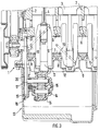
- einen nur teilweise dargestellten Querschnitt der Brennkraftmaschine entlang der Linie II-II nach Fig. 1 und
- Fig. 3
- einen nur teilweise dargestellten Längsschnitt der Brennkraftmaschine entlang der Linie III-III nach Fig. 1.
- Die in den Fig. 1 bis 3 als Ausführungsbeispiel dargestellte Brennkraftmaschine ist als vierzylindriger Reihenmotor mit einem Kurbelgehäuse 1 in Open-Deck-Bauweise ausgebildet. Das Kurbelgehäuse 1 hat vier Zylinderlaufbuchsen 2, in denen Kolben 3 geführt sind, deren Pleuel 4 mit einer Kurbelwelle 5 verbunden sind. Die Kurbelwelle 5 ist im Kurbelgehäuse 1 gelagert, wobei im Kurbelgehäuse die oberen Lagerhälften 6 ausgebildet sind. Die unteren Lagerhälften 7 sind in Lagerbrücken 8 ausgebildet, die zu einem leiterartigen Kurbelwellen-Lagerrahmen 9 zusammengefaßt sind. Der Kurbelwellen-Lagerrahmen 9 ist aus Leichtmetall gefertigt und hat im Bereich der unteren Lagerhälften 7 eisenmetallische Einsätze 10. Der die Kurbelwelle 5 aufnehmende Raum 11 ist durch eine Abdeckung 12 mit Ölhobeln nach unten abgeschottet. Die Abdeckung ist einstückig mit dem Kurbelwellen-Lagerrahmen 9 verbunden.
- Das Kurbelgehäuse 1 ist an seiner Unterseite durch eine angeflanschte Ölwanne 13 verschlossen. Im Betrieb der Brennkraftmaschine bildet sich in der Ölwanne unterhalb der Abdeckung 12 des Kurbelwellen-Lagerrahmens 9 ein Ölsumpf aus, der zur Schmiermittelversorgung der Brennkraftmaschine dient. An die Unterseite der Abdeckung 12 bzw. des Kurbelwellen-Lagerrahmens 9 ist eine Zahnradpumpe 14 angeflanscht, die zwei im Außeneingriff miteinander kämmende Zahnräder 15, 16 aufweist. Die Antriebswelle 17 der Zahnradpumpe 14 ist im Bereich der vorderen Stirnwand 18 der Ölwanne 13 mit einem Kettenrad 19 versehen, das über eine Antriebskette 20 mit einem auf dem stirnseitigen Wellenstummel 21 der Kurbelwelle 5 befestigten Kettenrad 22 angetrieben wird. Beide Kettenräder 19, 22 und die Antriebskette 20 befinden sich innerhalb des vom Kurbelgehäuse 1 und der Ölwanne 13 umschlossenen Raumes.
- Die Saugleitung 23 der Zahnradpumpe 14 ist mit einem Saugkorb 24 versehen, der im unteren Bereich der Ölwanne 13 unterhalb des sich im Betrieb einstellenden Ölspiegels angeordnet ist. Über den Saugkorb 24 und die Saugleitung 23 saugt die Zahnradpumpe 14 Schmiermittel (Öl) an und fördert es in ein Verbindungsrohr 25, das in das Pumpengehäuse 26 eingesteckt ist. Das gegenüberliegende Ende des Verbindungsrohres 25 ist in eine Öffnung 27 in der Ölwanne 13 eingesteckt, die mit einem Wärmetauscher 28 verbunden ist, der an die Außenseite der Ölwanne angesetzt ist. Das geförderte Öl der Zahnradpumpe 14 durchströmt den Wärmetauscher 28 und einen nachgeschalteten Ölfilter 29, von wo es nach erneutem Durchströmen des Wärmetauschers 28 in einen in die Ölwanne 13 ragenden Ölstutzen 30 gefördert wird. Dieser Ölstutzen 30 ist mit einem Rohranschluß 31 verbunden, der Teil einer aus mehreren Ölkanälen bestehenden horizontalen Ölgalerie 32 ist. Diese horizontale Ölgalerie 32 ist einstückig an der Unterseite der Abdeckung 12 ausgebildet und umfasst einen sich über nahezu die gesamte Länge der Brennkraftmaschine erstreckenden Längskanal 33 und zwei Seitenkanäle 34, 35. Der Längskanal 33 und die Seitenkanäle 34 und 35 sind jeweils endseitig verschlossen und mit vertikal verlaufenden, nicht näher dargestellten Steigleitungen 36 verbunden, über die die einzelnen zu schmierenden Bereiche, z.B. Kurbelwellenlagerung, Nockenwellenlagerung, Schlepphebellagerung, Nockenwellenverstellung, Spritzölkühlung und ähnliches mit Schmiermittel versorgt werden.
Claims (6)
- Brennkraftmaschine mit einem Kurbelgehäuse (1), einem daran befestigten Kurbelwellen-Lagerrahmen (9) und einer die Kurbelgehäuseunterseite verschließenden Ölwanne (13), und mit einem von einer Ölpumpe (14) gespeisten Schmierölverteilungssystem, dadurch gekennzeichnet, daß die Ölpumpe am Kurbelwellen-Lagerrahmen angebracht ist.
- Brennkraftmaschine nach Anspruch 1, dadurch gekennzeichnet, daß die Ölpumpe (14) an der Unterseite des Kurbelwellen-Lagerrahmens (9), innerhalb des von der Ölwanne (13) umschlossenen Raumes und im Bereich einer der Stirnseiten der Brennkraftmaschine angeordnet ist.
- Brennkraftmaschine nach Anspruch 1 oder 2, dadurch gekennzeichnet, daß die Ölpumpe (14) über einen Umschlingungstrieb (19, 20, 22) von der Kurbelwelle (5) angetrieben ist.
- Brennkraftmaschine nach einem der vorangehenden Ansprüche, dadurch gekennzeichnet, daß der Kurbelwellen-Lagerrahmen (9) an seiner Unterseite eine den Kurbelwellenraum teilweise abschottende Abdeckung (12) aufweist, die von der Ölpumpe (14) gespeiste Ölkanäle (32 bis 35) aufweist.
- Brennkraftmaschine nach Anspruch 4, dadurch gekennzeichnet, daß die Ölpumpe (14) an der Abdeckung (12) befestigt ist.
- Brennkraftmaschine nach einem der vorangehenden Ansprüche, dadurch gekennzeichnet, daß die Ölpumpe (14) über ein Rohrelement (25) mit einem externen Ölfilterelement (29) verbunden ist.
Priority Applications (2)
| Application Number | Priority Date | Filing Date | Title |
|---|---|---|---|
| EP19950107778 EP0744533B1 (de) | 1995-05-22 | 1995-05-22 | Brennkraftmaschine |
| DE59508566T DE59508566D1 (de) | 1995-05-22 | 1995-05-22 | Brennkraftmaschine |
Applications Claiming Priority (1)
| Application Number | Priority Date | Filing Date | Title |
|---|---|---|---|
| EP19950107778 EP0744533B1 (de) | 1995-05-22 | 1995-05-22 | Brennkraftmaschine |
Publications (2)
| Publication Number | Publication Date |
|---|---|
| EP0744533A1 true EP0744533A1 (de) | 1996-11-27 |
| EP0744533B1 EP0744533B1 (de) | 2000-07-12 |
Family
ID=8219269
Family Applications (1)
| Application Number | Title | Priority Date | Filing Date |
|---|---|---|---|
| EP19950107778 Expired - Lifetime EP0744533B1 (de) | 1995-05-22 | 1995-05-22 | Brennkraftmaschine |
Country Status (2)
| Country | Link |
|---|---|
| EP (1) | EP0744533B1 (de) |
| DE (1) | DE59508566D1 (de) |
Cited By (6)
| Publication number | Priority date | Publication date | Assignee | Title |
|---|---|---|---|---|
| EP1207277A1 (de) * | 2000-11-16 | 2002-05-22 | Honda Giken Kogyo Kabushiki Kaisha | Ölpumpenstützvorrichtung für eine Brennkraftmaschine |
| DE10159105A1 (de) * | 2001-12-01 | 2003-06-18 | Porsche Ag | Ölauffangvorrichtung für eine Brennkraftmaschine |
| US6644262B2 (en) | 2000-11-16 | 2003-11-11 | Honda Giken Kogyo Kabushiki Kaisha | Oil pump mounting structure for engine |
| EP1361345A1 (de) * | 2002-05-09 | 2003-11-12 | Aichi Kikai Kogyo Kabushiki Kaisha | Ölwanne |
| DE102006027660A1 (de) * | 2006-06-14 | 2007-12-20 | Schwäbische Hüttenwerke Automotive GmbH & Co. KG | Ölpumpenvorrichtung für eine Brennkraftmaschine mit einer Ölwanne |
| FR3038030A1 (fr) * | 2015-06-23 | 2016-12-30 | Renault Sa | Joint d'etancheite pour carter integrant un faisceau electrique |
Citations (5)
| Publication number | Priority date | Publication date | Assignee | Title |
|---|---|---|---|---|
| DE3142458A1 (de) | 1980-11-27 | 1982-06-09 | List Hans | Brennkraftmaschine |
| DE3203312C2 (de) | 1981-01-30 | 1986-08-28 | Honda Giken Kogyo K.K., Tokio/Tokyo | Von einer Schmierölpumpe gespeistes Schmierölverteilungssystem für eine Brennkraftmaschine |
| EP0255706A1 (de) * | 1986-08-05 | 1988-02-10 | Bayerische Motoren Werke Aktiengesellschaft, Patentabteilung AJ-3 | Einstellvorrichtung für lageverstellbar verbundene Bauteile, insbesondere Spannvorrichtung für Hüllgetriebe |
| DE4029428A1 (de) * | 1989-09-27 | 1991-04-04 | Volkswagen Ag | Brennkraftmaschine mit einer von ihrer kurbelwelle her angetriebenen oelpumpe |
| GB2280934A (en) * | 1990-10-31 | 1995-02-15 | Suzuki Motor Co | I.c. engine oil pump mounting |
-
1995
- 1995-05-22 DE DE59508566T patent/DE59508566D1/de not_active Expired - Fee Related
- 1995-05-22 EP EP19950107778 patent/EP0744533B1/de not_active Expired - Lifetime
Patent Citations (5)
| Publication number | Priority date | Publication date | Assignee | Title |
|---|---|---|---|---|
| DE3142458A1 (de) | 1980-11-27 | 1982-06-09 | List Hans | Brennkraftmaschine |
| DE3203312C2 (de) | 1981-01-30 | 1986-08-28 | Honda Giken Kogyo K.K., Tokio/Tokyo | Von einer Schmierölpumpe gespeistes Schmierölverteilungssystem für eine Brennkraftmaschine |
| EP0255706A1 (de) * | 1986-08-05 | 1988-02-10 | Bayerische Motoren Werke Aktiengesellschaft, Patentabteilung AJ-3 | Einstellvorrichtung für lageverstellbar verbundene Bauteile, insbesondere Spannvorrichtung für Hüllgetriebe |
| DE4029428A1 (de) * | 1989-09-27 | 1991-04-04 | Volkswagen Ag | Brennkraftmaschine mit einer von ihrer kurbelwelle her angetriebenen oelpumpe |
| GB2280934A (en) * | 1990-10-31 | 1995-02-15 | Suzuki Motor Co | I.c. engine oil pump mounting |
Cited By (7)
| Publication number | Priority date | Publication date | Assignee | Title |
|---|---|---|---|---|
| EP1207277A1 (de) * | 2000-11-16 | 2002-05-22 | Honda Giken Kogyo Kabushiki Kaisha | Ölpumpenstützvorrichtung für eine Brennkraftmaschine |
| US6644262B2 (en) | 2000-11-16 | 2003-11-11 | Honda Giken Kogyo Kabushiki Kaisha | Oil pump mounting structure for engine |
| DE10159105A1 (de) * | 2001-12-01 | 2003-06-18 | Porsche Ag | Ölauffangvorrichtung für eine Brennkraftmaschine |
| EP1316713A3 (de) * | 2001-12-01 | 2004-01-21 | Dr.Ing. h.c.F. Porsche Aktiengesellschaft | Ölauffangvorrichtung für eine Brennkraftmaschine |
| EP1361345A1 (de) * | 2002-05-09 | 2003-11-12 | Aichi Kikai Kogyo Kabushiki Kaisha | Ölwanne |
| DE102006027660A1 (de) * | 2006-06-14 | 2007-12-20 | Schwäbische Hüttenwerke Automotive GmbH & Co. KG | Ölpumpenvorrichtung für eine Brennkraftmaschine mit einer Ölwanne |
| FR3038030A1 (fr) * | 2015-06-23 | 2016-12-30 | Renault Sa | Joint d'etancheite pour carter integrant un faisceau electrique |
Also Published As
| Publication number | Publication date |
|---|---|
| DE59508566D1 (de) | 2000-08-17 |
| EP0744533B1 (de) | 2000-07-12 |
Similar Documents
| Publication | Publication Date | Title |
|---|---|---|
| DE69704917T2 (de) | Ölwanne und Lageranordnung für eine Kurbelwelle | |
| EP1316711B1 (de) | Brennkraftmaschine | |
| EP0807748B1 (de) | Brennkraftmaschine | |
| DE3444838C2 (de) | Gehäuse für Hubkolben-Brennkraftmaschine, insbesondere Motorblock | |
| DE69933416T2 (de) | Stützstruktur für Motorausgleichswellen | |
| EP0437681B1 (de) | Ölführungsgehäuse für eine Brennkraftmaschine | |
| DE69702781T2 (de) | Schmierungsanlage für eine rotierende Welle | |
| DE60209291T2 (de) | Ausgleichsvorrichtung für einen Motor | |
| DE19956732B4 (de) | Kühleinrichtung für einen Motor | |
| DE3342516A1 (de) | Verbrennungsmaschine | |
| EP0691458B1 (de) | Brennkraftmaschine mit zwei gegen die Vertikale geneigten Zylinderbänken | |
| DE10249174B4 (de) | Verbrennungsmotor vom V-Typ | |
| DE60114073T2 (de) | Durchblasgasabscheider | |
| EP0838577B1 (de) | Ölversorgungssystem für einen Kraftfahrzeugmotor | |
| WO2001071168A1 (de) | Ölauffangvorrichtung und ölpumpe für eine brennkraftmaschine | |
| EP0744533B1 (de) | Brennkraftmaschine | |
| DE2444659B2 (de) | ||
| DE10051131A1 (de) | Schmierungsstruktur für eine Brennkraftmaschine | |
| DE10107308B4 (de) | Schmiereinrichtung für Viertaktmotor | |
| DE19754009A1 (de) | Wassergekühlte Hubkolbenbrennkraftmaschine | |
| EP0305689B1 (de) | Schmiervorrichtung für einen Hubkolbenmotor | |
| DE10140876B4 (de) | Ölpumpenaufbau bei einem Motor | |
| DE19956818B4 (de) | Kühleinrichtung für einen Motor | |
| DE102018102528B4 (de) | Schmierstruktur für Verbrennungsmotor | |
| DE19633485B4 (de) | Flüssigkeitsgekühlte Brennkraftmaschine |
Legal Events
| Date | Code | Title | Description |
|---|---|---|---|
| PUAI | Public reference made under article 153(3) epc to a published international application that has entered the european phase |
Free format text: ORIGINAL CODE: 0009012 |
|
| 17P | Request for examination filed |
Effective date: 19950522 |
|
| AK | Designated contracting states |
Kind code of ref document: A1 Designated state(s): DE FR GB IT |
|
| 17Q | First examination report despatched |
Effective date: 19980807 |
|
| GRAG | Despatch of communication of intention to grant |
Free format text: ORIGINAL CODE: EPIDOS AGRA |
|
| GRAG | Despatch of communication of intention to grant |
Free format text: ORIGINAL CODE: EPIDOS AGRA |
|
| GRAH | Despatch of communication of intention to grant a patent |
Free format text: ORIGINAL CODE: EPIDOS IGRA |
|
| GRAH | Despatch of communication of intention to grant a patent |
Free format text: ORIGINAL CODE: EPIDOS IGRA |
|
| ITF | It: translation for a ep patent filed | ||
| GRAA | (expected) grant |
Free format text: ORIGINAL CODE: 0009210 |
|
| AK | Designated contracting states |
Kind code of ref document: B1 Designated state(s): DE FR GB IT |
|
| REF | Corresponds to: |
Ref document number: 59508566 Country of ref document: DE Date of ref document: 20000817 |
|
| ET | Fr: translation filed | ||
| GBT | Gb: translation of ep patent filed (gb section 77(6)(a)/1977) |
Effective date: 20001109 |
|
| PLBE | No opposition filed within time limit |
Free format text: ORIGINAL CODE: 0009261 |
|
| STAA | Information on the status of an ep patent application or granted ep patent |
Free format text: STATUS: NO OPPOSITION FILED WITHIN TIME LIMIT |
|
| 26N | No opposition filed | ||
| REG | Reference to a national code |
Ref country code: GB Ref legal event code: IF02 |
|
| PGFP | Annual fee paid to national office [announced via postgrant information from national office to epo] |
Ref country code: GB Payment date: 20040427 Year of fee payment: 10 |
|
| PGFP | Annual fee paid to national office [announced via postgrant information from national office to epo] |
Ref country code: DE Payment date: 20040510 Year of fee payment: 10 |
|
| PGFP | Annual fee paid to national office [announced via postgrant information from national office to epo] |
Ref country code: FR Payment date: 20040512 Year of fee payment: 10 |
|
| PG25 | Lapsed in a contracting state [announced via postgrant information from national office to epo] |
Ref country code: IT Free format text: LAPSE BECAUSE OF NON-PAYMENT OF DUE FEES;WARNING: LAPSES OF ITALIAN PATENTS WITH EFFECTIVE DATE BEFORE 2007 MAY HAVE OCCURRED AT ANY TIME BEFORE 2007. THE CORRECT EFFECTIVE DATE MAY BE DIFFERENT FROM THE ONE RECORDED. Effective date: 20050522 Ref country code: GB Free format text: LAPSE BECAUSE OF NON-PAYMENT OF DUE FEES Effective date: 20050522 |
|
| PG25 | Lapsed in a contracting state [announced via postgrant information from national office to epo] |
Ref country code: DE Free format text: LAPSE BECAUSE OF NON-PAYMENT OF DUE FEES Effective date: 20051201 |
|
| GBPC | Gb: european patent ceased through non-payment of renewal fee |
Effective date: 20050522 |
|
| PG25 | Lapsed in a contracting state [announced via postgrant information from national office to epo] |
Ref country code: FR Free format text: LAPSE BECAUSE OF NON-PAYMENT OF DUE FEES Effective date: 20060131 |
|
| REG | Reference to a national code |
Ref country code: FR Ref legal event code: ST Effective date: 20060131 |