EP0743408B1 - Dispositif de lissage de béton coulé - Google Patents
Dispositif de lissage de béton coulé Download PDFInfo
- Publication number
- EP0743408B1 EP0743408B1 EP96870064A EP96870064A EP0743408B1 EP 0743408 B1 EP0743408 B1 EP 0743408B1 EP 96870064 A EP96870064 A EP 96870064A EP 96870064 A EP96870064 A EP 96870064A EP 0743408 B1 EP0743408 B1 EP 0743408B1
- Authority
- EP
- European Patent Office
- Prior art keywords
- machine according
- striking
- machine
- frame part
- respect
- Prior art date
- Legal status (The legal status is an assumption and is not a legal conclusion. Google has not performed a legal analysis and makes no representation as to the accuracy of the status listed.)
- Expired - Lifetime
Links
Images


Classifications
-
- E—FIXED CONSTRUCTIONS
- E04—BUILDING
- E04G—SCAFFOLDING; FORMS; SHUTTERING; BUILDING IMPLEMENTS OR AIDS, OR THEIR USE; HANDLING BUILDING MATERIALS ON THE SITE; REPAIRING, BREAKING-UP OR OTHER WORK ON EXISTING BUILDINGS
- E04G21/00—Preparing, conveying, or working-up building materials or building elements in situ; Other devices or measures for constructional work
- E04G21/02—Conveying or working-up concrete or similar masses able to be heaped or cast
- E04G21/10—Devices for levelling, e.g. templates or boards
-
- E—FIXED CONSTRUCTIONS
- E01—CONSTRUCTION OF ROADS, RAILWAYS, OR BRIDGES
- E01C—CONSTRUCTION OF, OR SURFACES FOR, ROADS, SPORTS GROUNDS, OR THE LIKE; MACHINES OR AUXILIARY TOOLS FOR CONSTRUCTION OR REPAIR
- E01C19/00—Machines, tools or auxiliary devices for preparing or distributing paving materials, for working the placed materials, or for forming, consolidating, or finishing the paving
- E01C19/22—Machines, tools or auxiliary devices for preparing or distributing paving materials, for working the placed materials, or for forming, consolidating, or finishing the paving for consolidating or finishing laid-down unset materials
- E01C19/30—Tamping or vibrating apparatus other than rollers ; Devices for ramming individual paving elements
- E01C19/34—Power-driven rammers or tampers, e.g. air-hammer impacted shoes for ramming stone-sett paving; Hand-actuated ramming or tamping machines, e.g. tampers with manually hoisted dropping weight
- E01C19/40—Power-driven rammers or tampers, e.g. air-hammer impacted shoes for ramming stone-sett paving; Hand-actuated ramming or tamping machines, e.g. tampers with manually hoisted dropping weight adapted to impart a smooth finish to the paving, e.g. tamping or vibrating finishers
-
- E—FIXED CONSTRUCTIONS
- E04—BUILDING
- E04F—FINISHING WORK ON BUILDINGS, e.g. STAIRS, FLOORS
- E04F21/00—Implements for finishing work on buildings
- E04F21/20—Implements for finishing work on buildings for laying flooring
- E04F21/24—Implements for finishing work on buildings for laying flooring of masses made in situ, e.g. smoothing tools
- E04F21/241—Elongated smoothing blades or plates, e.g. screed apparatus
- E04F21/242—Elongated smoothing blades or plates, e.g. screed apparatus with vibrating means, e.g. vibrating screeds
-
- E—FIXED CONSTRUCTIONS
- E04—BUILDING
- E04F—FINISHING WORK ON BUILDINGS, e.g. STAIRS, FLOORS
- E04F21/00—Implements for finishing work on buildings
- E04F21/20—Implements for finishing work on buildings for laying flooring
- E04F21/24—Implements for finishing work on buildings for laying flooring of masses made in situ, e.g. smoothing tools
- E04F21/241—Elongated smoothing blades or plates, e.g. screed apparatus
- E04F21/244—Elongated smoothing blades or plates, e.g. screed apparatus with means to adjust the working angle of the leveling blade or plate
Definitions
- the present invention relates to a machine for striking off poured concrete composed of frame parts which carry the elements for striking off the concrete and the control members thereof, which frame parts are equipped with wheels, at least some of which are drive wheels.
- the concrete surface Upon construction of monolithic concrete floors, the concrete surface is mostly struck off manually with vibration beams or struck off strokes. If it concerns larger surfaces, it is already possible to strike off the concrete surface by means of machines which are provided with vibration beams and instruments pertaining thereto. To enable to strike off an as large as possible surface, these machines are provided with a telescopic arm to which the striking off means are applied. This was realised for always enabling to strike off a distance as large as possible. These machines are always set up out off the poured concrete and operate from a stationary position.
- a second clear drawback is the pressure which is exerted by the weight of the machine through the intermediary of the rods of the cage wheels onto a plastic foil or a clay cloth.
- the often used plastic foils or clay cloths onto which the liquid concrete is poured, are in the widths used therefor, never resistant to the pressure exerted by the cage wheels, while the rotation of these cage wheels over these foils or cloths regularly tears the foil material.
- An object of the invention is therefore to provide a machine which enables to achieve striking off concrete floor surfaces under all circumstances on a very flexible manner, without damaging the foil materials described hereinabove.
- said wheels are equipped with tires having a tire width of substantially 18 cm.
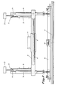
- Figure 1 is a schematic side view of the machine according to the invention.
- Figure 2 is a schematic top view of the machine in a position wherein both frame parts and the arm connected to the first frame part are directed according to one and the same centre line.
- Figures 3 and 4 are, on a smaller scale, two schematic views of different arrangements of the arm with respect to the first frame part and of the support beam with a striking off unit connected to the arm.
- Figure 5 is, on an enlarged scale, a schematic side view of the first frame part and of the support and transverse beams mounted thereon.
- Figure 6 is a schematic front view of the support beam with the striking off unit mounted thereto.
- Figure 7 is a view similar to the view according to Figure 6, but with respect to an alternative.
- Figures 8 and 9 are, on a smaller scale, two schematic views of the machine such as represented in Figures 3 and 4, but with respect to an alternative.
- the machine illustrated by these figures, consists in the embodiment described herein by way of example, of a first frame part 1 and a second frame part 2 which are hingedly connected to each other at the vertical hinge axis 3.
- the first frame part 1 carries the required instruments for striking off the poured concrete while the second frame part is equipped with the different mechanic and hydraulic control members of the machines.
- Very characterising for this embodiment of the invention is the presence of each time two narrow wheels 4 as well on the first as on the second frame part.
- the diameter of the wheels 4 and the thickness of the tires 5 which equip these wheels are calculated in such a manner that the machine can be moved without problems through the poured concrete.
- without problems it is meant :
- Handling the machine occurs on a technically very reliable manner by mounting a hydraulic cylinder 6 between the first frame part 1 and the second frame part 2.
- This hydraulic cylinder with hinge point 7 on the first frame part and 8 on the second frame part is illustrated with a dotted/dashed line in Figures 1, 3 and 4.
- a hydraulic cylinder 6 By using a hydraulic cylinder 6, a simple and light control of the machine is rendered possible and the first frame part 1 and the second frame part 2 can be set up under very different angles with respect to each other. This is illustrated i.a. in Figures 3 and 4.
- an arm 9 is mounted with the possibility to turn.
- the arm 9 is mounted with respect to the first frame part through the intermediary of a rotary ring 10.
- a hydraulic cylinder This cylinder 11 has its first hinge point 12 on the rotary ring 10 and a second rotation point 17 on the first frame part.
- This second hydraulic cylinder 11 permits to set up the arm with respect to the frame part under a plurality of angles with respect to each other. Also this is very clearly illustrated in Figures 3 and 4.
- the arm 9 which can be turned on itself with respect to the first frame part in the horizontal plane is, approximately at free end height thereof, provided with a second rotary ring, which is illustrated Figures 2, 3 and 4 with reference 13.
- the transverse beam 14 is fixed.
- the support beam 24 is fixed and this through the intermediary of a number of parts which will be explained further in detail.
- the turning of the transverse beam 14 with respect to the arm 9 is realised here by a hydraulic cylinder 15, with a first hinge point 16 on the transverse beam and a second hinge point 17 on the rotary ring 13.
- a hollow column 18 is mounted each time on its extremity. This hollow columns serve to guide tubes in up- and downwards direction.
- hydraulic cylinders 20 are mounted parallel to these tubes, on the one hand to the tubes and, on the other hand, to the transverse beam.
- the sensors 21 act on a laser beacon, as known, which has not been illustrated in the figures.
- the support beam 24 is suspended to the tubes 19 by means of a knee joint 23.
- a scraper 25 is fixed to this support beam 24.
- a roller 26 is also fixed to the support beam, the rotation direction of which is opposite to the direction wherein the machine moves.
- the support beam 24 serves also as suspension point of a vibration beam 27 which is driven by vibration motor 28.
- Small hydraulic cylinders 29 are hingedly connected, on the one hand with the support beam 24 and are connected, on the other hand, with an arm 30 at the bottom of the tubes 19.
- the object is to be allowed to modify the horizontal position of the support beam and thus to adapt it to the local or temporary requirements.
- the machine shows, as it appears from the description and the figures annexed hereto, a very compact and light structure.
- the required means for striking off the concrete can be set up and used under very different angles, as it appears from these figures.
- the machine can be provided with wheels equipped with tires, which solves hitherto very inconvenient problems.
Landscapes
- Engineering & Computer Science (AREA)
- Architecture (AREA)
- Civil Engineering (AREA)
- Structural Engineering (AREA)
- Mechanical Engineering (AREA)
- On-Site Construction Work That Accompanies The Preparation And Application Of Concrete (AREA)
Claims (11)
- Machine pour égaliser du béton coulé composée de pièces de châssis (1, 2) qui supportent les éléments pour égaliser le béton et les organes de commande de ceux-ci, lesquelles pièces de châssis sont équipées de roues (4), dont au moins certaines sont des roues d'entraínement, caractérisée en ce que lesdites roues (4) sont équipées de pneus (5) ayant une largeur de pneu de 18 cm tout au plus.
- Machine pour égaliser du béton coulé suivant la revendication 1, caractérisée en ce qu'elle est composée de deux pièces de châssis (1, 2) reliées par articulation l'une à l'autre suivant un axe vertical (3), dont la première pièce de châssis (1) supporte les éléments pour égaliser le béton, tandis que la seconde pièce de châssis (2) comprend les organes de commande de la machine, chaque pièce de châssis étant en outre équipée de roues.
- Machine suivant la revendication 2, caractérisée en ce que les pièces de châssis (1, 2) susdites sont reliées l'une à l'autre au moyen d'un cylindre hydraulique (6) qui permet à ces pièces de châssis (1, 2) de s'articuler l'une par rapport à l'autre.
- Machine suivant l'une quelconque des revendications 1 à 3, caractérisée en ce que les éléments précités pour réaliser le béton coulé se composent d'un racleur (25), d'un rouleau rotatif (26) et d'une poutrelle vibrante (27).
- Machine suivant la revendication 4, caractérisée en ce que le racleur (25), le rouleau (26) et la poutrelle vibrante (27) sont montés sur une poutrelle de support (24), dont la hauteur est ajustable au moyen de détecteurs (21) par rapport à une balise laser.
- Machine suivant la revendication 5, caractérisée en ce que la poutrelle de support (24) est suspendue à ses deux extrémités à un tube (19), lequel tube est guidé dans des colonnes creuses (18) fixées à une poutrelle transversale, lesquels tubes (19) sont de plus équipés à l'extrémité supérieure de détecteurs (21) et sont déplacés vers le haut et vers le bas en fonction de la détection du faisceau laser, tandis que la poutrelle transversale (24) peut être orientée par rapport à un bras (9) qui fait partie de la première pièce de châssis (1).
- Machine suivant la revendication 6, caractérisée en ce que la poutrelle de support (24) est suspendue aux tubes précités par l'intermédiaire d'une articulation coudée (23).
- Machine suivant l'une ou l'autre des revendications 6 et 7, caractérisée en ce que les tubes (19), auxquels la poutrelle de support (24) est fixée, sont reliés à l'extrémité inférieure à ladite poutrelle de support (24) par l'intermédiaire de cylindres hydrauliques (29), d'une manière telle que l'angle sous lequel la poutrelle de support (24) s'étend par rapport au plan horizontal puisse être ajusté.
- Machine suivant l'une quelconque des revendications 6 à 8, caractérisée en ce qu'un cylindre hydraulique (15) est monté entre la première pièce de châssis (1) et la poutrelle transversale (14) pour assurer la rotation de la poutrelle transversale (14) par rapport au bras (9) appartenant à la première pièce de châssis (1).
- Machine suivant l'une quelconque des revendications 3 à 6, caractérisée en ce qu'un anneau rotatif hydraulique (13) est monté entre le bras (9) et la poutrelle transversale (14) pour assurer la rotation de la poutrelle transversale (14) par rapport au bras (9).
- Machine suivant l'une quelconque des revendications 6 à 10, caractérisée en ce que sur le bras (9) est prévu un guide (32) grâce auquel la poutrelle transversale (14) peut être déplacée latéralement dans les deux directions au moyen d'un cylindre hydraulique (31).
Applications Claiming Priority (2)
| Application Number | Priority Date | Filing Date | Title |
|---|---|---|---|
| BE9500456A BE1009417A3 (nl) | 1995-05-19 | 1995-05-19 | Machine voor het afstrijken van gestort beton. |
| BE9500456 | 1995-05-19 |
Publications (2)
| Publication Number | Publication Date |
|---|---|
| EP0743408A1 EP0743408A1 (fr) | 1996-11-20 |
| EP0743408B1 true EP0743408B1 (fr) | 1998-10-07 |
Family
ID=3888995
Family Applications (1)
| Application Number | Title | Priority Date | Filing Date |
|---|---|---|---|
| EP96870064A Expired - Lifetime EP0743408B1 (fr) | 1995-05-19 | 1996-05-20 | Dispositif de lissage de béton coulé |
Country Status (3)
| Country | Link |
|---|---|
| EP (1) | EP0743408B1 (fr) |
| BE (1) | BE1009417A3 (fr) |
| DE (1) | DE69600743T2 (fr) |
Cited By (1)
| Publication number | Priority date | Publication date | Assignee | Title |
|---|---|---|---|---|
| US7195423B2 (en) | 2004-07-26 | 2007-03-27 | Somero Enterprises, Inc. | Powered strike-off plow |
Families Citing this family (5)
| Publication number | Priority date | Publication date | Assignee | Title |
|---|---|---|---|---|
| US6695532B2 (en) * | 2001-06-13 | 2004-02-24 | Delaware Capital Formation, Inc. | Concrete finishing apparatus |
| EP1325993A1 (fr) * | 2002-01-07 | 2003-07-09 | Thomas Cincis | Appareil et méthode de lissage |
| GB0918761D0 (en) * | 2009-10-27 | 2009-12-09 | Sinnamon Trevor H | Screed working apparatus |
| CN111576803A (zh) * | 2020-04-26 | 2020-08-25 | 哈尔滨工业大学(深圳)(哈尔滨工业大学深圳科技创新研究院) | 一种墙面施工机器人和墙面机器人控制方法 |
| CN112459437A (zh) * | 2020-11-30 | 2021-03-09 | 湖南哈工聚能科技有限公司 | 一种建筑激光地面整平机器人 |
Family Cites Families (3)
| Publication number | Priority date | Publication date | Assignee | Title |
|---|---|---|---|---|
| DE3704697C1 (en) * | 1987-02-14 | 1988-08-04 | Peter Pertl | Paving finisher |
| US5039249A (en) * | 1989-08-18 | 1991-08-13 | Hansen Joel D | Apparatus for screening and trowelling concrete |
| NL9001726A (nl) * | 1990-07-31 | 1992-02-17 | Bredel Exploitatie Bv | Vloeregalisatie-inrichting. |
-
1995
- 1995-05-19 BE BE9500456A patent/BE1009417A3/nl not_active IP Right Cessation
-
1996
- 1996-05-20 DE DE69600743T patent/DE69600743T2/de not_active Expired - Fee Related
- 1996-05-20 EP EP96870064A patent/EP0743408B1/fr not_active Expired - Lifetime
Cited By (4)
| Publication number | Priority date | Publication date | Assignee | Title |
|---|---|---|---|---|
| US7195423B2 (en) | 2004-07-26 | 2007-03-27 | Somero Enterprises, Inc. | Powered strike-off plow |
| US7407339B2 (en) | 2004-07-26 | 2008-08-05 | Somero Enterprises, Inc. | Powered strike-off plow |
| US7854565B2 (en) | 2004-07-26 | 2010-12-21 | Somero Enterprises, Inc. | Method of establishing a desired grade of an uncured concrete surface |
| US8038366B2 (en) | 2004-07-26 | 2011-10-18 | Somero Enterprises, Inc. | Wheeled concrete screeding device |
Also Published As
| Publication number | Publication date |
|---|---|
| EP0743408A1 (fr) | 1996-11-20 |
| BE1009417A3 (nl) | 1997-03-04 |
| DE69600743D1 (de) | 1998-11-12 |
| DE69600743T2 (de) | 1999-05-27 |
Similar Documents
| Publication | Publication Date | Title |
|---|---|---|
| CA2005242A1 (fr) | Methode et appareil amelioree de lissage | |
| US4792190A (en) | Machine for cutting curbstones, sidewalks or the like | |
| EP0743408B1 (fr) | Dispositif de lissage de béton coulé | |
| JPH0358640B2 (fr) | ||
| RU2053114C1 (ru) | Форма для изготовления бетонных изделий | |
| SU828981A3 (ru) | Механизм шагани проходческойМАшиНы | |
| US11965345B2 (en) | Concrete screeding machine for tilt-up panels | |
| JP4623618B2 (ja) | 法面への吹付材料の吹付装置 | |
| JPH0460194B2 (fr) | ||
| CN117300424B (zh) | 一种适用于狭窄空间的钢筋焊接设备 | |
| JPH06312422A (ja) | ワイヤーソーイング機 | |
| KR102261936B1 (ko) | 교량점검 차량용 가변형 아웃트리거 | |
| JPH10120369A (ja) | 地下工事用クレーン | |
| JP3472372B2 (ja) | パイル圧入地盤改良機における伸縮式リーダー並びにこれに用いる油圧モーター走行装置およびチェーン駆動装置 | |
| WO2021036749A1 (fr) | Robot de lissage | |
| JPH0445440B2 (fr) | ||
| JP2622320B2 (ja) | 建築物架設用工場の建屋施工法 | |
| SU874838A1 (ru) | Бетоноукладчик | |
| JPH0312944B2 (fr) | ||
| JP4394371B2 (ja) | クローラ走行装置 | |
| SU1201409A1 (ru) | Устройство дл сооружени покрытий из бетонных смесей | |
| JP3175146B2 (ja) | プレキャストコンクリート板据付装置 | |
| SU1094889A1 (ru) | Устройство дл укреплени каналов торкретированием | |
| SU878856A1 (ru) | Устройство дл разравнивани бетонной смеси | |
| JPS61270406A (ja) | 橋梁メンテナンス装置 |
Legal Events
| Date | Code | Title | Description |
|---|---|---|---|
| PUAI | Public reference made under article 153(3) epc to a published international application that has entered the european phase |
Free format text: ORIGINAL CODE: 0009012 |
|
| AK | Designated contracting states |
Kind code of ref document: A1 Designated state(s): BE DE FR IT NL |
|
| 17P | Request for examination filed |
Effective date: 19970207 |
|
| GRAG | Despatch of communication of intention to grant |
Free format text: ORIGINAL CODE: EPIDOS AGRA |
|
| GRAG | Despatch of communication of intention to grant |
Free format text: ORIGINAL CODE: EPIDOS AGRA |
|
| GRAH | Despatch of communication of intention to grant a patent |
Free format text: ORIGINAL CODE: EPIDOS IGRA |
|
| 17Q | First examination report despatched |
Effective date: 19980218 |
|
| GRAH | Despatch of communication of intention to grant a patent |
Free format text: ORIGINAL CODE: EPIDOS IGRA |
|
| GRAA | (expected) grant |
Free format text: ORIGINAL CODE: 0009210 |
|
| AK | Designated contracting states |
Kind code of ref document: B1 Designated state(s): BE DE FR IT NL |
|
| REF | Corresponds to: |
Ref document number: 69600743 Country of ref document: DE Date of ref document: 19981112 |
|
| ET | Fr: translation filed | ||
| PLBE | No opposition filed within time limit |
Free format text: ORIGINAL CODE: 0009261 |
|
| STAA | Information on the status of an ep patent application or granted ep patent |
Free format text: STATUS: NO OPPOSITION FILED WITHIN TIME LIMIT |
|
| 26N | No opposition filed | ||
| PGFP | Annual fee paid to national office [announced via postgrant information from national office to epo] |
Ref country code: FR Payment date: 20030508 Year of fee payment: 8 |
|
| PGFP | Annual fee paid to national office [announced via postgrant information from national office to epo] |
Ref country code: BE Payment date: 20030520 Year of fee payment: 8 |
|
| PGFP | Annual fee paid to national office [announced via postgrant information from national office to epo] |
Ref country code: DE Payment date: 20030529 Year of fee payment: 8 |
|
| PGFP | Annual fee paid to national office [announced via postgrant information from national office to epo] |
Ref country code: NL Payment date: 20030530 Year of fee payment: 8 |
|
| PG25 | Lapsed in a contracting state [announced via postgrant information from national office to epo] |
Ref country code: BE Free format text: LAPSE BECAUSE OF NON-PAYMENT OF DUE FEES Effective date: 20040531 |
|
| BERE | Be: lapsed |
Owner name: *ALFA INDUSTRIES Effective date: 20040531 |
|
| PG25 | Lapsed in a contracting state [announced via postgrant information from national office to epo] |
Ref country code: NL Free format text: LAPSE BECAUSE OF NON-PAYMENT OF DUE FEES Effective date: 20041201 Ref country code: DE Free format text: LAPSE BECAUSE OF NON-PAYMENT OF DUE FEES Effective date: 20041201 |
|
| PG25 | Lapsed in a contracting state [announced via postgrant information from national office to epo] |
Ref country code: FR Free format text: LAPSE BECAUSE OF NON-PAYMENT OF DUE FEES Effective date: 20050131 |
|
| NLV4 | Nl: lapsed or anulled due to non-payment of the annual fee |
Effective date: 20041201 |
|
| REG | Reference to a national code |
Ref country code: FR Ref legal event code: ST |
|
| PG25 | Lapsed in a contracting state [announced via postgrant information from national office to epo] |
Ref country code: IT Free format text: LAPSE BECAUSE OF NON-PAYMENT OF DUE FEES Effective date: 20050520 |