EP0742386B1 - Steuerung für ein automatisches Getriebe - Google Patents
Steuerung für ein automatisches Getriebe Download PDFInfo
- Publication number
- EP0742386B1 EP0742386B1 EP96107385A EP96107385A EP0742386B1 EP 0742386 B1 EP0742386 B1 EP 0742386B1 EP 96107385 A EP96107385 A EP 96107385A EP 96107385 A EP96107385 A EP 96107385A EP 0742386 B1 EP0742386 B1 EP 0742386B1
- Authority
- EP
- European Patent Office
- Prior art keywords
- clutch
- oil pressure
- throttle opening
- automatic transmission
- ideal
- Prior art date
- Legal status (The legal status is an assumption and is not a legal conclusion. Google has not performed a legal analysis and makes no representation as to the accuracy of the status listed.)
- Expired - Lifetime
Links
- 230000005540 biological transmission Effects 0.000 title claims description 55
- 230000000994 depressogenic effect Effects 0.000 claims description 11
- 230000000977 initiatory effect Effects 0.000 claims 1
- 230000007935 neutral effect Effects 0.000 description 19
- 238000010586 diagram Methods 0.000 description 16
- 230000035939 shock Effects 0.000 description 6
- 230000032683 aging Effects 0.000 description 3
- 230000000694 effects Effects 0.000 description 3
- 239000012530 fluid Substances 0.000 description 3
- 238000001514 detection method Methods 0.000 description 2
- 238000010276 construction Methods 0.000 description 1
- 230000000881 depressing effect Effects 0.000 description 1
- 238000010408 sweeping Methods 0.000 description 1
Images


Classifications
-
- F—MECHANICAL ENGINEERING; LIGHTING; HEATING; WEAPONS; BLASTING
- F16—ENGINEERING ELEMENTS AND UNITS; GENERAL MEASURES FOR PRODUCING AND MAINTAINING EFFECTIVE FUNCTIONING OF MACHINES OR INSTALLATIONS; THERMAL INSULATION IN GENERAL
- F16H—GEARING
- F16H61/00—Control functions within control units of change-speed- or reversing-gearings for conveying rotary motion ; Control of exclusively fluid gearing, friction gearing, gearings with endless flexible members or other particular types of gearing
- F16H61/04—Smoothing ratio shift
- F16H61/06—Smoothing ratio shift by controlling rate of change of fluid pressure
- F16H61/061—Smoothing ratio shift by controlling rate of change of fluid pressure using electric control means
-
- B—PERFORMING OPERATIONS; TRANSPORTING
- B60—VEHICLES IN GENERAL
- B60W—CONJOINT CONTROL OF VEHICLE SUB-UNITS OF DIFFERENT TYPE OR DIFFERENT FUNCTION; CONTROL SYSTEMS SPECIALLY ADAPTED FOR HYBRID VEHICLES; ROAD VEHICLE DRIVE CONTROL SYSTEMS FOR PURPOSES NOT RELATED TO THE CONTROL OF A PARTICULAR SUB-UNIT
- B60W30/00—Purposes of road vehicle drive control systems not related to the control of a particular sub-unit, e.g. of systems using conjoint control of vehicle sub-units
- B60W30/18—Propelling the vehicle
- B60W30/18009—Propelling the vehicle related to particular drive situations
- B60W30/18027—Drive off, accelerating from standstill
-
- F—MECHANICAL ENGINEERING; LIGHTING; HEATING; WEAPONS; BLASTING
- F16—ENGINEERING ELEMENTS AND UNITS; GENERAL MEASURES FOR PRODUCING AND MAINTAINING EFFECTIVE FUNCTIONING OF MACHINES OR INSTALLATIONS; THERMAL INSULATION IN GENERAL
- F16H—GEARING
- F16H59/00—Control inputs to control units of change-speed-, or reversing-gearings for conveying rotary motion
- F16H59/68—Inputs being a function of gearing status
- F16H2059/6807—Status of gear-change operation, e.g. clutch fully engaged
-
- F—MECHANICAL ENGINEERING; LIGHTING; HEATING; WEAPONS; BLASTING
- F16—ENGINEERING ELEMENTS AND UNITS; GENERAL MEASURES FOR PRODUCING AND MAINTAINING EFFECTIVE FUNCTIONING OF MACHINES OR INSTALLATIONS; THERMAL INSULATION IN GENERAL
- F16H—GEARING
- F16H61/00—Control functions within control units of change-speed- or reversing-gearings for conveying rotary motion ; Control of exclusively fluid gearing, friction gearing, gearings with endless flexible members or other particular types of gearing
- F16H2061/0075—Control functions within control units of change-speed- or reversing-gearings for conveying rotary motion ; Control of exclusively fluid gearing, friction gearing, gearings with endless flexible members or other particular types of gearing characterised by a particular control method
- F16H2061/0087—Adaptive control, e.g. the control parameters adapted by learning
-
- F—MECHANICAL ENGINEERING; LIGHTING; HEATING; WEAPONS; BLASTING
- F16—ENGINEERING ELEMENTS AND UNITS; GENERAL MEASURES FOR PRODUCING AND MAINTAINING EFFECTIVE FUNCTIONING OF MACHINES OR INSTALLATIONS; THERMAL INSULATION IN GENERAL
- F16H—GEARING
- F16H61/00—Control functions within control units of change-speed- or reversing-gearings for conveying rotary motion ; Control of exclusively fluid gearing, friction gearing, gearings with endless flexible members or other particular types of gearing
- F16H61/20—Preventing gear creeping ; Transmission control during standstill, e.g. hill hold control
- F16H2061/207—Preventing gear creeping ; Transmission control during standstill, e.g. hill hold control by neutral control
-
- F—MECHANICAL ENGINEERING; LIGHTING; HEATING; WEAPONS; BLASTING
- F16—ENGINEERING ELEMENTS AND UNITS; GENERAL MEASURES FOR PRODUCING AND MAINTAINING EFFECTIVE FUNCTIONING OF MACHINES OR INSTALLATIONS; THERMAL INSULATION IN GENERAL
- F16H—GEARING
- F16H2312/00—Driving activities
- F16H2312/02—Driving off
- F16H2312/022—Preparing to drive off
-
- F—MECHANICAL ENGINEERING; LIGHTING; HEATING; WEAPONS; BLASTING
- F16—ENGINEERING ELEMENTS AND UNITS; GENERAL MEASURES FOR PRODUCING AND MAINTAINING EFFECTIVE FUNCTIONING OF MACHINES OR INSTALLATIONS; THERMAL INSULATION IN GENERAL
- F16H—GEARING
- F16H2342/00—Calibrating
- F16H2342/04—Calibrating engagement of friction elements
-
- F—MECHANICAL ENGINEERING; LIGHTING; HEATING; WEAPONS; BLASTING
- F16—ENGINEERING ELEMENTS AND UNITS; GENERAL MEASURES FOR PRODUCING AND MAINTAINING EFFECTIVE FUNCTIONING OF MACHINES OR INSTALLATIONS; THERMAL INSULATION IN GENERAL
- F16H—GEARING
- F16H59/00—Control inputs to control units of change-speed-, or reversing-gearings for conveying rotary motion
- F16H59/14—Inputs being a function of torque or torque demand
- F16H59/18—Inputs being a function of torque or torque demand dependent on the position of the accelerator pedal
- F16H59/22—Idle position
-
- F—MECHANICAL ENGINEERING; LIGHTING; HEATING; WEAPONS; BLASTING
- F16—ENGINEERING ELEMENTS AND UNITS; GENERAL MEASURES FOR PRODUCING AND MAINTAINING EFFECTIVE FUNCTIONING OF MACHINES OR INSTALLATIONS; THERMAL INSULATION IN GENERAL
- F16H—GEARING
- F16H59/00—Control inputs to control units of change-speed-, or reversing-gearings for conveying rotary motion
- F16H59/14—Inputs being a function of torque or torque demand
- F16H59/24—Inputs being a function of torque or torque demand dependent on the throttle opening
-
- F—MECHANICAL ENGINEERING; LIGHTING; HEATING; WEAPONS; BLASTING
- F16—ENGINEERING ELEMENTS AND UNITS; GENERAL MEASURES FOR PRODUCING AND MAINTAINING EFFECTIVE FUNCTIONING OF MACHINES OR INSTALLATIONS; THERMAL INSULATION IN GENERAL
- F16H—GEARING
- F16H59/00—Control inputs to control units of change-speed-, or reversing-gearings for conveying rotary motion
- F16H59/36—Inputs being a function of speed
- F16H59/44—Inputs being a function of speed dependent on machine speed of the machine, e.g. the vehicle
-
- F—MECHANICAL ENGINEERING; LIGHTING; HEATING; WEAPONS; BLASTING
- F16—ENGINEERING ELEMENTS AND UNITS; GENERAL MEASURES FOR PRODUCING AND MAINTAINING EFFECTIVE FUNCTIONING OF MACHINES OR INSTALLATIONS; THERMAL INSULATION IN GENERAL
- F16H—GEARING
- F16H59/00—Control inputs to control units of change-speed-, or reversing-gearings for conveying rotary motion
- F16H59/50—Inputs being a function of the status of the machine, e.g. position of doors or safety belts
- F16H59/54—Inputs being a function of the status of the machine, e.g. position of doors or safety belts dependent on signals from the brakes, e.g. parking brakes
Definitions
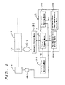
- the present invention relates to a control system for an automatic transmission and, more particularly, to an automatic transmission control system for achieving ideal engaging characteristics in a clutch and preventing the racing of the engine and the application shock of the clutch.
- reference numeral 10 designates an engine; characters C1 a first clutch adapted to be applied, when a forward running range is selected, for transmitting the rotation of the engine 10 to a transmission mechanism of a speed change unit 16; characters C-1 a hydraulic servo for applying/releasing the first clutch C1; and numeral 100 starting state detecting means for detecting a vehicle starting state which is dictated by the dissatisfaction of at least one of the conditions that a throttle opening ⁇ is fully closed, the not-shown brake pedal is depressed and that the vehicle speed is substantially zero.
- numeral 49 designates an engine RPM sensor acting as applied/released state detecting means for detecting the applied/released state of the first clutch C1 as an engine RPM N E ; numeral 103 hydraulic control means for controlling a C-1 oil pressure P C1 to be fed to the hydraulic servo C-1; and numeral 41 an automatic transmission control unit acting as a control system.
- the automatic transmission control unit 41 is provided with: fed characteristic storing means 105 stored with a sweep-up pressure P C1U for achieving the ideal engaging characteristics of the first clutch C1, in accordance with the elapsed time and the throttle opening ⁇ ; applied/released state characteristic storing means 106 stored with an engine RPM N EO indicating the applied/released state of the first clutch C1 if the ideal engaging characteristics are achieved, in accordance with the elapsed time T and the throttle opening ⁇ ; correction setting means 108 for determining the difference between the engine RPM N E , which is detected by the engine RPM sensor 49 and indicates the actual applied/released state of the first clutch C1, and the engine RPM N EO , which is read out from the applied/released state storing means 106 and indicates the ideal applied/released state, to set an oil pressure correction P C1m in accordance with that difference; and hydraulic command means 109 for reading out the sweep-up pressure P C1P from the fed characteristic storing means 105, if the vehicle starting state is
- the rotation, as generated by the engine 10, is transmitted through an output shaft 11 to the torque converter 12.
- This torque converter 12 transmits the rotation of the engine 10 to an output shaft 14 through a fluid (or working oil) but transmits the rotation directly to the output shaft 14, when the vehicle speed exceeds a predetermined value so that a lockup clutch L/C is applied.
- the first planetary gear unit 31 is composed of: a ring gear R 1 connected to a drive unit casing 34 through the third brake B3 and the one-way clutch F2 which are arranged in parallel with each other; a sun gear S 1 formed on a sun gear shaft 36 fitted on and rotatably supported by the output shaft 14; a carrier CR 1 connected to the counter drive gear 21; and pinions P 1A and P 1B meshing between the ring gear R 1 and the sun gear S 1 and rotatably supported by the carrier CR 1 .
- sun gear shaft 36 is connected through the second clutch C2 to the output shaft 14.
- the sun gear shaft 36 is further connected through the first brake B1 to the drive unit casing 34 and through the one-way clutch F1 and the second brake B2, as arranged in series, to the drive unit casing 34.
- the second planetary gear unit 32 is composed of: a ring gear R 2 connected through the first clutch C1 to the output shaft 14; a sun gear S 2 formed on the sun gear shaft 36 integrally with the sun gear S 1 ; a carrier CR 2 connected to the carrier CR 1 ; and a pinion P 2 meshing between the ring gear R 2 and the sun gear S 2 , rotatably supported by the carrier CR 2 and formed integrally with the pinion P 1B .
- the third planetary gear unit 38 is composed of: a ring gear R 3 connected to the counter driven gear 22; a sun gear S 3 formed on a sun gear shaft 39 rotatably fitted on the output shaft 23; a carrier CR 3 fixed on the output shaft 23; and a pinion P 3 meshing between the ring gear R 3 and the sun gear S 3 and rotatably supported by the carrier CR 3 .
- characters C1 designate the first clutch, characters C2 the second clutch; characters C3 the third clutch; characters B1 the first brake; characters B2 the second brake; characters B3 the third brake; characters B4 the fourth brake; and characters F1 to F3 the one-way clutches.
- letter R designates a reverse running range; letter N an N-range; letter D a forward running range (as will be called the "D-range"); characters 1ST a 1st-speed gear stage; characters 2ND a 2nd-speed gear stage; characters 3RD a 3rd-speed gear stage; and characters 4TH a 4th-speed gear stage.
- symbol ⁇ indicates that the first clutch C1, the second clutch C2, the third clutch C3, the first brake B1, the second brake B2, the third brake B3 and the fourth brake B4 are applied, and that the one-way clutches F1 to F3 are locked.
- symbol X indicates that the first clutch C1, the second clutch C2, the third clutch C3, the first brake B1, the second brake B2, the third brake B3 and the fourth brake B4 are released, and that the one-way clutches F1 to F3 are free.
- the first clutch C1 and the fourth brake B4 are applied to lock the one-way clutches F2 and F3. Then, the rotation of the output shaft 14 is transmitted through the first clutch C1 to the ring gear R 2 . In this state, the rotation of the ring gear R 1 is blocked by the one-way clutch F2 so that the rotation of the carrier CR 2 is drastically decelerated and transmitted to the counter driven gear 21 while rotating the sun gear S 2 idly.
- the first clutch C1, the third clutch C3, the first brake B1 and the second brake B2 are applied to lock the one-way clutch F1.
- the rotation of the output shaft 14 is transmitted through the first clutch C1 to the ring gear R 2 .
- the rotation of this ring gear R 2 is decelerated and transmitted to the carrier CR 2 because the rotation of the sun gear S 2 is blocked by the second brake B2 and the one-way clutch F1.
- the rotation of the carrier CR 2 is transmitted to the counter drive gear 21 while rotating the ring gear R 1 idly.
- the first clutch C1, the second clutch C2, the third clutch C3 and the second brake B2 are applied. Then, the rotation of the output shaft 14 is transmitted through the first clutch C1 to the ring gear R 2 and through the second clutch C2 to the sun gear S 2 to bring the first planetary gear unit 31 and the second planetary gear unit 32 into direct-coupled states. As a result, the rotation of the output shaft 11 is unchangedly transmitted to the counter drive gear 21.
- Fig. 4 is a hydraulic circuit diagram of an essential portion of the hydraulic control unit in the embodiment of the present invention.
- a primary valve 59 regulates the oil pressure coming from the a pump 50 and outputs it as a line pressure to an oil line L-4.
- a manual valve 55 is provided with ports 1, 2, 3, D, P L and R so that the line pressure, as outputted from the primary valve 59, is fed via the oil line L-4 to the port P L .
- the manual valve 55 is connected to the not-shown shift lever, which is operated to output the line pressure as the 1st-range pressure, the 2nd-range pressure, 3rd-range pressure, the D-range pressure and the R-range pressure from the ports 1, 2, 3, D and R.
- the solenoid signals corresponding to the shift output are turned ON/OFF.
- the solenoid valves are opened/closed in response to the ON/OFF of the solenoid signals, the not-shown 1-2 shift valve, 2-3 shift valve and 3-4 shift valve are switched.
- the C-1 control valve 67 is fed with the D-range pressure via an oil line L-3 so that it regulates the fed D-range pressure to the C-1 oil pressure P C1 corresponding to the throttle pressure P TH from the linear solenoid valve 66 and feeds it to an oil line L-15.
- the solenoid valve S3 is turned OFF so that the neutral relay valve 64 takes its lower half position.
- the oil under the D-range pressure is fed via the oil lines L-3 and L-18 and the neutral relay valve 64 and the oil line L-17 to the hydraulic servo C-1.
- the neutral relay valve 64, the linear solenoid valve 66, the C-1 control valve 67 and the hydraulic servo C-1 thus far described constitute the hydraulic control means 103 (Fig. 1).
- the neutral control is executed by the automatic transmission control unit 41.
- the throttle pressure P TH is gradually lowered to effect the sweep-down, and the pressure is then repeatedly lowered and raised to hold the released state of the first clutch C1.
- the throttle pressure P TH is gradually raised.
- the vehicle stop state is detected by satisfying all the conditions that the engine 10 is in the idling state, that the throttle opening ⁇ is fully closed, that the not-shown brake pedal is depressed to turn ON the brake switch 48, that the D-range is selected by the not-shown shift lever, and that the vehicle speed is not higher than a set value but substantially zero, it is decided the starting condition holds.
- Step S2 A third solenoid signal for opening/ closing the solenoid valve S3 (Fig. 4) is turned ON.
- Step S4 The satisfaction of the condition for ending the neutral control is awaited. If, in this case, any of the following conditions is dissatisfied: that the throttle opening ⁇ is fully closed; that the brake switch 48 is ON; that the D-range is selected; and the vehicle speed is not higher than the set value but substantially zero, the vehicle starting condition is detected, but the vehicle stopping condition is not. Hence, it is decided that the condition for ending the neutral control is satisfied.
- Step S5 The clutch application is executed.
- Fig. 6 is a time chart of an application routine in the embodiment of the present invention. Incidentally, the abscissa of Fig. 6 indicates the time, and the ordinate indicates the RPM and the C-1 oil pressure P C1 .
- reference letters N E designate the actual engine RPM, as detected by the engine RPM sensor 49 (Fig. 2); characters N EO an ideal engine RPM; characters ⁇ N E the rotational difference between the actual engine RPM N E and the ideal engine RPM N EO ; and characters P C1 the C-1 oil pressure to be fed to the hydraulic servo C-1.
- the application is started at timing tl. If the not-shown accelerator pedal is depressed, for example, the actual engine RPM N E rises with lapse of time from the idling RPM.
- the actual engine RPM N E is the one which is actually detected by the engine RPM sensor 49 and rises faster than the ideal engine RPM N EO which is required for achieving the ideal engaging characteristics of the first clutch C1.
- the rotational difference ⁇ N E is established between the actual engine RPM N E and the ideal engine RPM N EO .
- the fed characteristic storing means which is stored with the oil pressure for achieving the ideal engaging characteristics of the first clutch C1
- the difference between the ideal engaging characteristics and the actual engaging characteristics does not grow large.
- This makes it possible to set the oil pressure correction P C1m at a small value and to improve the follow-up and the convergence.
- the applied/released state of the first clutch C1 is detected in terms of the actual engine RPM N E , its detection can be facilitated to improve the controllability.
- Fig. 7 is a chart showing a sub-routine of the application in the embodiment of the present invention
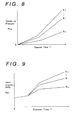
- Fig. 8 is a diagram presenting a map of a sweep-up pressure in the embodiment of the present invention
- Fig. 9 is a diagram presenting a map of an ideal engine RPM in the embodiment of the present invention
- Fig. 10 is an engaging characteristic diagram of a first clutch in the embodiment of the present invention
- Fig. 11 is a characteristic diagram of an engine RPM in the embodiment of the present invention
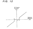
- Fig. 12 is a diagram presenting a correction map in the embodiment of the present invention.
- Step S5-1 The clutch input side RPM N C1 at the instant when the condition for ending the neutral control is satisfied is set to a value N C1S .
- Step S5-2 The initial engaging pressure P C1S as the shelf pressure is added to the stop oil pressure P C1N as the base pressure, and the sum is used as the C-1 oil pressure P C1 .
- the initial engaging pressure P C1S is generated by the not-shown initial engaging pressure generating means in the automatic transmission control unit (Fig. 2) and can be set to such a value as to move the not-shown piston of the hydraulic servo C-1 (Fig. 4) and to reduce the application shock which is caused by the engagement.
- the oil pressure correction P C1m is zero.
- the first clutch C1 is held in the state immediately before the start of its engagement so that the piston of the hydraulic servo C-1 is placed in a slightly retracted position. If the C-1 oil pressure P C1 is raised from that state, the piston is prevented from instantly moving by the starting resistance.
- the initial engaging pressure P C1S is added at first to the sweep-up pressure P C1U , and this sum is outputted to the hydraulic control means 103 (Fig. 1) so that the piston can be moved against the aforementioned starting resistance. As a result, the engaging time can be shortened.
- Step S5-5 The automatic transmission control unit 41 reads the throttle opening ⁇ which is detected by the throttle opening sensor 50.
- Step S5-6 The hydraulic command means 109 reads the sweep-up pressure P C1U for sweeping up the C-1 oil pressure P C1 , with reference to the map of Fig. 8, which is stored in the fed characteristic storing means 105.
- the sweep-up pressure P C1U is set to correspond to the elapsed time T, as measured by the timer, and the throttle opening ⁇ .
- Step S5-7 The hydraulic command means 109 sets the C-1 oil pressure P C1 by adding the initial engaging pressure P C1S , the sweep-up pressure P C1U and the oil pressure correction P C1m to the stop oil pressure P C1N , and outputs the sum to the hydraulic control means 103.
- reference letters N EA designate an engine RPM of the case in which the engine 10 is driven with a constant throttle opening ⁇ but without exerting any load. Moreover, this engine RPM N EA is lowered by the value ⁇ N E which is determined by the characteristics of the torque converter 12 and the degree of engagement of the first clutch C1, when the engine 10 and the first clutch C1 are connected through the torque converter 12 so that the first clutch C1 may be applied with the engaging characteristics, as illustrated in Fig. 10.
- the value which is made lower by the value ⁇ N E than the engine RPM N EA is set to the ideal engine RPM N EO .
- Step S5-10 The correction setting means 108 decides the rotational difference ⁇ N E by subtracting the ideal engine RPM N EO from the actual engine RPM N E .
- Step S5-11 The correction setting means 108 determined the oil pressure correction P C1m corresponding to the rotational difference ⁇ N E , with reference to Fig. 12. In this case, the oil pressure correction P C1m is set to zero if the rotational difference ⁇ N E is smaller than the set value ⁇ .
- Step S5-12 It is decided whether or not the application of the first clutch C1 is ended.
- the routine advances to Step S5-13, if the application is ended, but returns to Step S5-5 if the application is not ended.
- whether or not the application of the first clutch C1 is ended is decided by multiplying the output RPM N O , as detected by the vehicle speed sensor 51, and the gear ratio i of the speed change unit 16 to calculate the value N O ⁇ i and by comparing the value, which is calculated by subtracting the value N O i from the clutch input side RPM N C1 , with a set value ⁇ N R2 .
- it is decided that the application of the first clutch C1 is ended, if the following relations hold: N C1 - N O ⁇ i ⁇ N R2 .
- Step S5-13 The third solenoid valve is turned OFF.
- the control system for an automatic transmission comprises: a clutch for transmitting the rotation of an engine to the transmission mechanism of a speed change unit; a hydraulic servo for applying/releasing the clutch; starting state detecting means for detecting the vehicle starting condition in which at least one of the following conditions is dissatisfied: that the throttle opening is fully closed; that the brake pedal is depressed; and that the vehicle speed is substantially zero; throttle opening detecting means for detecting the throttle opening of the engine; applied/released state detecting means for detecting the applied/released state of the clutch; hydraulic control means for controlling the oil pressure to be fed to the hydraulic servo; and a control unit.
- the starting state detecting means detects the vehicle starting state.
- control unit read outs the oil pressure for achieving the ideal engaging characteristics of the clutch from the fed characteristics storing means and adds the oil pressure correction to the read oil pressure until it outputs the sum to the hydraulic control means.
- control unit includes: stop state detecting means for detecting the vehicle stop state in which a forward running range is selected, in which the throttle opening is fully closed, in which the brake pedal is depressed and in which the vehicle speed is substantially zero; and stop oil pressure generating means for generating a stop oil pressure immediately before the clutch starts its engagement, if the vehicle stop state is detected.
- the hydraulic command means reads out the oil pressure from the fed characteristic storing means, if the vehicle starting state is detected, and adds the stop oil pressure to the read oil pressure.
- the clutch In the neutral control, the clutch is held in the state immediately before the start of engagement, so that the piston of the hydraulic servo is placed in a slightly retracted position. If the oil pressure is raised from this state, the piston is prevented from quick movement by a starting resistance.
Landscapes
- Engineering & Computer Science (AREA)
- General Engineering & Computer Science (AREA)
- Mechanical Engineering (AREA)
- Physics & Mathematics (AREA)
- Fluid Mechanics (AREA)
- Automation & Control Theory (AREA)
- Transportation (AREA)
- Control Of Transmission Device (AREA)
- Control Of Driving Devices And Active Controlling Of Vehicle (AREA)
- Control Of Vehicle Engines Or Engines For Specific Uses (AREA)
Claims (5)
- Steuerungssystem für ein Automatikgetriebe mit:wobei die Steuereinheit aufweist:einer Kupplung (C1) zum Übertragen der Drehbewegung eines Motors (10) zum Getriebemechanismus einer Gangschalteinheit (16);einer Hydraulik-Servo (C-1) zum Ein-/Ausrücken der Kupplung (C1);einer Anfahrzustanderfassungseinrichtung (100) zum Erfassen eines Fahrzeuganfahrzustands, in dem mindestens eine der folgenden Bedingungen nicht erfüllt ist: die Drosselklappenöffnung ist vollständig geschlossen; das Bremspedal ist betätigt; und die Fahrzeuggeschwindigkeit beträgt im wesentlichen null;einer Drosselklappenöffnungserfassungseinrichtung (50) zum Erfassen der Drosselklappenöffnung () des Motors;einer Einrückzustanderfassungseinrichtung (49) zum Erfassen des Einrückzustands der Kupplung (C1);einer Hydrauliksteuerungseinrichtung (103) zum Steuern des der Hydraulik-Servo (C-1) zuzuführenden Hydraulikdrucks (PC1); undeiner Steuereinheit (41)einen Zeitgeber zum Messen einer vom Start einer Einrücksteuerung der Kupplung verstrichenen Zeit (T);eine Zufuhrkennlinienspeichereinrichtung (105) zum Speichern des Öldruckwertes (PC1U) zum Erreichen der idealen Einrückkennlinie der Kupplung (C1) als Funktion der verstrichenen Zeit (T) und der Drosselklappenöffnung ();eine Einrückkennlinienspeichereinrichtung (106) zum Speichern der idealen Einrückkennlinie der Kupplung (C1) als Funktion der verstrichenen Zeit (T) und der Drosselklappenöffnung ();eine Einrichtung (108) zum Festlegen eines Korrekturwertes zum Festlegen eines Öldruckkorrekturwertes (PC1m) als Funktion der Differenz zwischen dem durch die Einrückzustanderfassungseinrichtung (49) erfaßten realen Einrückzustand der Kupplung (C1) und dem aus der Einrückkennliniespeichereinrichtung (106) ausgelesenen idealen Einrückzustand, der der verstrichenen Zeit und der Drosselklappenöffnung entspricht; undeine Hydraulikbefehleinrichtung (109) zum Auslesen des der verstrichenen Zeit und der Drosselklappenöffnung entsprechenden Öldruckwertes (PC1U) aus der Zufuhrkennlinienspeichereinrichtung (105) und zum Addieren des Öldruckkorrekturwertes (PC1m) zum ausgelesenen Öldruckwert (PC1U), wenn der Fahrzeuganfahrzustand erfaßt wird.
- Steuerungssystem für ein Automatikgetriebe nach Anspruch 1,
wobei der Einrückzustand der Kupplung (C1) durch die Einrückzustanderfassungseinrichtung (49) bezüglich einer Motordrehzahl (NE) erfaßt wird, und wobei die Einrückkennlinienspeichereinrichtung (106) die Motordrehzahl (NEO) für den Fall, in dem der ideale Einrückzustand erreicht wird, als Funktion der verstrichenen Zeit (T) und der Drosselklappenöffnung () speichert. - Steuerungssystem für ein Automatikgetriebe nach Anspruch 1 oder 2,wobei die Steuereinheit (41) ferner aufweist: eine Haltezustanderfassungseinrichtung zum Erfassen eines Fahrzeug haltezustands, in dem ein Vorwärtsfahrbereich ausgewählt ist, die Drosselklappenöffnung () vollständig geschlossen ist, das Bremspedal betätigt ist und die Fahrzeuggeschwindigkeit im wesentlichen null beträgt; und eine Halteöldruckerzeugungseinrichtung zum Erzeugen eines Halteöldrucks (PC1N) unmittelbar bevor die Kupplung (C1) beginnt einzurücken, wenn der Fahrzeughaltezustand erfaßt wird; undwobei die Hydraulikbefehleinrichtung (109) den Öldruckwert (PC1U) aus der Zufuhrkennlinienspeichereinrichtung (105) ausliest, wenn der Fahrzeuganfahrzustand erfaßt wird, und den Halteöldruck (PC1N) zum ausgelesenen Öldruckwert (PC1U) addiert.
- Steuerungssystem für ein Automatikgetriebe nach Anspruch 3,wobei die Steuereinheit (41) ferner aufweist: eine Anfangseinrückdruckerzeugungseinrichtung zum Erzeugen eines Anfangseinrückdrucks (PC1S); undwobei die Hydraulikbefehleinrichtung (109) die Summe aus dem ausgelesenen Öldruckwert (PC1U) und dem Anfangseinrückdruck (PC1S) der Hydrauliksteuerungseinrichtung (103) zuführt und dann zusätzlich den Halteöldruck (PC1N) addiert.
- Steuerungssystem für ein Automatikgetriebe nach einem der Ansprüche 1 bis 4,
wobei die Einrichtung (108) zum Festlegen eines Korrekturwertes den Öldruckkorrekturwert (PC1m) auf null setzt, wenn die Differenz zwischen dem realen Einrückzustand und dem idealen Einrückzustand kleiner ist als ein vorgegebener Wert.
Applications Claiming Priority (3)
| Application Number | Priority Date | Filing Date | Title |
|---|---|---|---|
| JP11501095 | 1995-05-12 | ||
| JP115010/95 | 1995-05-12 | ||
| JP7115010A JP3003540B2 (ja) | 1995-05-12 | 1995-05-12 | 自動変速機の制御装置 |
Publications (3)
| Publication Number | Publication Date |
|---|---|
| EP0742386A2 EP0742386A2 (de) | 1996-11-13 |
| EP0742386A3 EP0742386A3 (de) | 1996-11-20 |
| EP0742386B1 true EP0742386B1 (de) | 2000-08-09 |
Family
ID=14652045
Family Applications (1)
| Application Number | Title | Priority Date | Filing Date |
|---|---|---|---|
| EP96107385A Expired - Lifetime EP0742386B1 (de) | 1995-05-12 | 1996-05-09 | Steuerung für ein automatisches Getriebe |
Country Status (4)
| Country | Link |
|---|---|
| US (1) | US5690581A (de) |
| EP (1) | EP0742386B1 (de) |
| JP (1) | JP3003540B2 (de) |
| DE (1) | DE69609659T2 (de) |
Families Citing this family (14)
| Publication number | Priority date | Publication date | Assignee | Title |
|---|---|---|---|---|
| NO314174B1 (no) * | 1995-12-18 | 2003-02-10 | Luk Getriebe Systeme Gmbh | Motorkjöretöy |
| US6001044A (en) * | 1995-12-18 | 1999-12-14 | Luk Getriebe-Systeme Gmbh | Motor vehicle |
| JP3634947B2 (ja) * | 1997-08-08 | 2005-03-30 | ジヤトコ株式会社 | 自動変速機のニュートラル制御装置 |
| US6317671B1 (en) * | 1999-04-26 | 2001-11-13 | Aisin Aw Co., Ltd. | Control apparatus for automatic transmission |
| DE10230774A1 (de) * | 2002-07-09 | 2004-01-22 | Zf Friedrichshafen Ag | Steuersystem für ein Anfahrschaltelement eines automatisierten Getriebes oder Automatgetriebes im Notbetrieb |
| JP4737687B2 (ja) | 2004-07-01 | 2011-08-03 | ヤマハ発動機株式会社 | エンジンおよび鞍乗型車両 |
| KR100655701B1 (ko) * | 2004-08-17 | 2006-12-11 | 현대자동차주식회사 | 자동 변속기의 유압 제어 시스템 |
| JP4723233B2 (ja) | 2004-12-10 | 2011-07-13 | ヤマハ発動機株式会社 | 鞍乗型車両の変速制御装置、制御方法及び鞍乗型車両 |
| JP4686179B2 (ja) | 2004-12-10 | 2011-05-18 | ヤマハ発動機株式会社 | クラッチ接続制御装置、クラッチの接続制御方法及び鞍乗型車両 |
| JP2006170227A (ja) | 2004-12-10 | 2006-06-29 | Yamaha Motor Co Ltd | クラッチアクチュエータ及び鞍乗型車両 |
| JP2006170224A (ja) * | 2004-12-10 | 2006-06-29 | Yamaha Motor Co Ltd | クラッチ制御装置、クラッチ制御方法及び鞍乗型車両 |
| JP5261224B2 (ja) * | 2009-02-12 | 2013-08-14 | トヨタ自動車株式会社 | 車両用自動変速機の制御装置 |
| FR2957883B1 (fr) * | 2010-03-25 | 2013-01-18 | Peugeot Citroen Automobiles Sa | Procede de demarrage automatise d'un vehicule automobile |
| KR101703602B1 (ko) * | 2015-08-13 | 2017-02-07 | 현대자동차 주식회사 | 유압 클러치용 유압 센서의 선형성 편차 학습 방법 및 장치 |
Citations (2)
| Publication number | Priority date | Publication date | Assignee | Title |
|---|---|---|---|---|
| JPS61249839A (ja) * | 1985-04-30 | 1986-11-07 | Nissan Motor Co Ltd | 自動変速機の発進クラツチ制御装置 |
| DE4217270A1 (de) * | 1992-05-25 | 1993-12-02 | Opel Adam Ag | Verfahren zur Korrektur der Schaltqualität eines automatischen Getriebes |
Family Cites Families (12)
| Publication number | Priority date | Publication date | Assignee | Title |
|---|---|---|---|---|
| US4331226A (en) * | 1979-05-07 | 1982-05-25 | Volkswagenwerk Aktiengesellschaft | Device for automatic actuation of an automobile clutch |
| DE3205767A1 (de) * | 1982-02-18 | 1983-08-25 | Robert Bosch Gmbh, 7000 Stuttgart | Einrichtung zum einstellen des druckes des arbeitsmediums in automatischen stufengetrieben |
| CA1250642A (en) * | 1983-06-30 | 1989-02-28 | Toshihiro Hattori | Method of controlling the starting of a vehicle having automatic clutch |
| DE3611256C2 (de) * | 1985-04-06 | 1994-08-25 | Nissan Motor | Vorrichtung zum Regeln der Anfahrkupplung eines automatischen Getriebes |
| DE68921625T2 (de) * | 1988-11-24 | 1995-09-07 | Komatsu Mfg Co Ltd | Verfahren und vorrichtung zur steuerung von getrieben. |
| JPH0742998B2 (ja) * | 1988-12-15 | 1995-05-15 | 株式会社ゼクセル | 車輛用発進制御装置及び方法 |
| US5056639A (en) * | 1990-09-10 | 1991-10-15 | Zahnradfabrik Friedrichshafen Ag | Device and method for the control of an automatic vehicle clutch |
| US5301572A (en) * | 1990-10-02 | 1994-04-12 | Mitsubishi Jidosha Kogyo Kabushiki Kaisha | Shift control method for an automatic transmission of an automotive vehicle |
| US5151858A (en) * | 1990-10-05 | 1992-09-29 | Saturn Corporation | Multiple mode adaptive pressure control for an automatic transmission |
| JPH04194451A (ja) * | 1990-11-28 | 1992-07-14 | Hitachi Ltd | 自動変速制御装置 |
| US5275267A (en) * | 1991-10-07 | 1994-01-04 | Eaton Corporation | Closed loop launch and creep control for automatic clutch with robust algorithm |
| US5343782A (en) * | 1992-08-31 | 1994-09-06 | General Motors Corporation | Anti-flare method using offgoing slip speed and rate of change of slip-speed to determine pressure compensation for incoming clutch |
-
1995
- 1995-05-12 JP JP7115010A patent/JP3003540B2/ja not_active Expired - Fee Related
-
1996
- 1996-05-09 DE DE69609659T patent/DE69609659T2/de not_active Expired - Fee Related
- 1996-05-09 EP EP96107385A patent/EP0742386B1/de not_active Expired - Lifetime
- 1996-05-10 US US08/645,959 patent/US5690581A/en not_active Expired - Fee Related
Patent Citations (2)
| Publication number | Priority date | Publication date | Assignee | Title |
|---|---|---|---|---|
| JPS61249839A (ja) * | 1985-04-30 | 1986-11-07 | Nissan Motor Co Ltd | 自動変速機の発進クラツチ制御装置 |
| DE4217270A1 (de) * | 1992-05-25 | 1993-12-02 | Opel Adam Ag | Verfahren zur Korrektur der Schaltqualität eines automatischen Getriebes |
Also Published As
| Publication number | Publication date |
|---|---|
| EP0742386A3 (de) | 1996-11-20 |
| EP0742386A2 (de) | 1996-11-13 |
| US5690581A (en) | 1997-11-25 |
| JPH08300982A (ja) | 1996-11-19 |
| DE69609659D1 (de) | 2000-09-14 |
| DE69609659T2 (de) | 2000-12-07 |
| JP3003540B2 (ja) | 2000-01-31 |
Similar Documents
| Publication | Publication Date | Title |
|---|---|---|
| US5741200A (en) | Control apparatus for an automatic transmission | |
| EP0742386B1 (de) | Steuerung für ein automatisches Getriebe | |
| EP0627336A2 (de) | Schaltsteuerung für ein automatisches Getriebe | |
| EP0742395B1 (de) | Steuereinrichtung für ein automatisches Getriebe | |
| EP0681122B1 (de) | Steuerungssystem für Automatikgetriebe | |
| US5505673A (en) | Control system for automatic transmissions | |
| EP0709601B1 (de) | Steuerungssystem für Automatikgetriebe | |
| US4783743A (en) | Improved apparatus for determining whether gear-shifting in an automatic transmission control system is in process or has been completed | |
| EP0742388B1 (de) | Steuerung für ein automatisches Getriebe | |
| JPH08303569A (ja) | 自動変速機の制御装置 | |
| US5769753A (en) | Control system for automatic transmission | |
| JP3155027B2 (ja) | 自動変速機の変速制御装置 | |
| US5653660A (en) | Control system for automatic transmission | |
| US5547436A (en) | Control system for automatic transmission | |
| US6729987B2 (en) | Apparatus for controlling vehicle automatic transmission | |
| EP0789170B1 (de) | Drucksteuerung für automatische Getriebe beim Anfahren des Fahrzeugs | |
| JP3402220B2 (ja) | 自動変速機の制御装置 | |
| EP0781944B1 (de) | Geschwindigkeitsabhängiges Regelsystem für den Öldruck eines automatischen Getriebes | |
| JP2814478B2 (ja) | 自動変速機の制御装置 | |
| JP2783708B2 (ja) | 自動変速機の制御装置 | |
| KR100245883B1 (ko) | 자동 변속기의 n 레인지에서 d 레인지로의 변속시 쇼크 저감 방법 | |
| JPS6184472A (ja) | 自動変速機の制御装置 | |
| JPH0534550B2 (de) | ||
| GB2307015A (en) | Shift control system for automatic transmission | |
| JPS61248961A (ja) | 自動変速機の制御装置 |
Legal Events
| Date | Code | Title | Description |
|---|---|---|---|
| PUAI | Public reference made under article 153(3) epc to a published international application that has entered the european phase |
Free format text: ORIGINAL CODE: 0009012 |
|
| PUAL | Search report despatched |
Free format text: ORIGINAL CODE: 0009013 |
|
| AK | Designated contracting states |
Kind code of ref document: A2 Designated state(s): DE GB |
|
| AK | Designated contracting states |
Kind code of ref document: A3 Designated state(s): DE GB |
|
| 17P | Request for examination filed |
Effective date: 19961119 |
|
| 17Q | First examination report despatched |
Effective date: 19970825 |
|
| GRAG | Despatch of communication of intention to grant |
Free format text: ORIGINAL CODE: EPIDOS AGRA |
|
| GRAG | Despatch of communication of intention to grant |
Free format text: ORIGINAL CODE: EPIDOS AGRA |
|
| GRAG | Despatch of communication of intention to grant |
Free format text: ORIGINAL CODE: EPIDOS AGRA |
|
| GRAH | Despatch of communication of intention to grant a patent |
Free format text: ORIGINAL CODE: EPIDOS IGRA |
|
| GRAH | Despatch of communication of intention to grant a patent |
Free format text: ORIGINAL CODE: EPIDOS IGRA |
|
| GRAA | (expected) grant |
Free format text: ORIGINAL CODE: 0009210 |
|
| AK | Designated contracting states |
Kind code of ref document: B1 Designated state(s): DE GB |
|
| REF | Corresponds to: |
Ref document number: 69609659 Country of ref document: DE Date of ref document: 20000914 |
|
| EN | Fr: translation not filed | ||
| PG25 | Lapsed in a contracting state [announced via postgrant information from national office to epo] |
Ref country code: GB Free format text: LAPSE BECAUSE OF NON-PAYMENT OF DUE FEES Effective date: 20010509 |
|
| PLBE | No opposition filed within time limit |
Free format text: ORIGINAL CODE: 0009261 |
|
| STAA | Information on the status of an ep patent application or granted ep patent |
Free format text: STATUS: NO OPPOSITION FILED WITHIN TIME LIMIT |
|
| 26N | No opposition filed | ||
| GBPC | Gb: european patent ceased through non-payment of renewal fee |
Effective date: 20010509 |
|
| PGFP | Annual fee paid to national office [announced via postgrant information from national office to epo] |
Ref country code: DE Payment date: 20080515 Year of fee payment: 13 |
|
| PG25 | Lapsed in a contracting state [announced via postgrant information from national office to epo] |
Ref country code: DE Free format text: LAPSE BECAUSE OF NON-PAYMENT OF DUE FEES Effective date: 20091201 |