EP0742072A2 - Symmetrische, mehrachsige, mit Linearmotoren versehene Werkzeugmaschine - Google Patents
Symmetrische, mehrachsige, mit Linearmotoren versehene Werkzeugmaschine Download PDFInfo
- Publication number
- EP0742072A2 EP0742072A2 EP95118569A EP95118569A EP0742072A2 EP 0742072 A2 EP0742072 A2 EP 0742072A2 EP 95118569 A EP95118569 A EP 95118569A EP 95118569 A EP95118569 A EP 95118569A EP 0742072 A2 EP0742072 A2 EP 0742072A2
- Authority
- EP
- European Patent Office
- Prior art keywords
- gantry
- saddle
- ram
- spindle
- frame
- Prior art date
- Legal status (The legal status is an assumption and is not a legal conclusion. Google has not performed a legal analysis and makes no representation as to the accuracy of the status listed.)
- Granted
Links
Images


Classifications
-
- B—PERFORMING OPERATIONS; TRANSPORTING
- B23—MACHINE TOOLS; METAL-WORKING NOT OTHERWISE PROVIDED FOR
- B23Q—DETAILS, COMPONENTS, OR ACCESSORIES FOR MACHINE TOOLS, e.g. ARRANGEMENTS FOR COPYING OR CONTROLLING; MACHINE TOOLS IN GENERAL CHARACTERISED BY THE CONSTRUCTION OF PARTICULAR DETAILS OR COMPONENTS; COMBINATIONS OR ASSOCIATIONS OF METAL-WORKING MACHINES, NOT DIRECTED TO A PARTICULAR RESULT
- B23Q5/00—Driving or feeding mechanisms; Control arrangements therefor
- B23Q5/22—Feeding members carrying tools or work
- B23Q5/28—Electric drives
-
- B—PERFORMING OPERATIONS; TRANSPORTING
- B23—MACHINE TOOLS; METAL-WORKING NOT OTHERWISE PROVIDED FOR
- B23Q—DETAILS, COMPONENTS, OR ACCESSORIES FOR MACHINE TOOLS, e.g. ARRANGEMENTS FOR COPYING OR CONTROLLING; MACHINE TOOLS IN GENERAL CHARACTERISED BY THE CONSTRUCTION OF PARTICULAR DETAILS OR COMPONENTS; COMBINATIONS OR ASSOCIATIONS OF METAL-WORKING MACHINES, NOT DIRECTED TO A PARTICULAR RESULT
- B23Q1/00—Members which are comprised in the general build-up of a form of machine, particularly relatively large fixed members
- B23Q1/01—Frames, beds, pillars or like members; Arrangement of ways
- B23Q1/017—Arrangements of ways
-
- B—PERFORMING OPERATIONS; TRANSPORTING
- B23—MACHINE TOOLS; METAL-WORKING NOT OTHERWISE PROVIDED FOR
- B23Q—DETAILS, COMPONENTS, OR ACCESSORIES FOR MACHINE TOOLS, e.g. ARRANGEMENTS FOR COPYING OR CONTROLLING; MACHINE TOOLS IN GENERAL CHARACTERISED BY THE CONSTRUCTION OF PARTICULAR DETAILS OR COMPONENTS; COMBINATIONS OR ASSOCIATIONS OF METAL-WORKING MACHINES, NOT DIRECTED TO A PARTICULAR RESULT
- B23Q1/00—Members which are comprised in the general build-up of a form of machine, particularly relatively large fixed members
- B23Q1/25—Movable or adjustable work or tool supports
- B23Q1/44—Movable or adjustable work or tool supports using particular mechanisms
- B23Q1/56—Movable or adjustable work or tool supports using particular mechanisms with sliding pairs only, the sliding pairs being the first two elements of the mechanism
- B23Q1/60—Movable or adjustable work or tool supports using particular mechanisms with sliding pairs only, the sliding pairs being the first two elements of the mechanism two sliding pairs only, the sliding pairs being the first two elements of the mechanism
- B23Q1/62—Movable or adjustable work or tool supports using particular mechanisms with sliding pairs only, the sliding pairs being the first two elements of the mechanism two sliding pairs only, the sliding pairs being the first two elements of the mechanism with perpendicular axes, e.g. cross-slides
- B23Q1/621—Movable or adjustable work or tool supports using particular mechanisms with sliding pairs only, the sliding pairs being the first two elements of the mechanism two sliding pairs only, the sliding pairs being the first two elements of the mechanism with perpendicular axes, e.g. cross-slides a single sliding pair followed perpendicularly by a single sliding pair
- B23Q1/626—Movable or adjustable work or tool supports using particular mechanisms with sliding pairs only, the sliding pairs being the first two elements of the mechanism two sliding pairs only, the sliding pairs being the first two elements of the mechanism with perpendicular axes, e.g. cross-slides a single sliding pair followed perpendicularly by a single sliding pair followed perpendicularly by a single sliding pair
-
- B—PERFORMING OPERATIONS; TRANSPORTING
- B23—MACHINE TOOLS; METAL-WORKING NOT OTHERWISE PROVIDED FOR
- B23Q—DETAILS, COMPONENTS, OR ACCESSORIES FOR MACHINE TOOLS, e.g. ARRANGEMENTS FOR COPYING OR CONTROLLING; MACHINE TOOLS IN GENERAL CHARACTERISED BY THE CONSTRUCTION OF PARTICULAR DETAILS OR COMPONENTS; COMBINATIONS OR ASSOCIATIONS OF METAL-WORKING MACHINES, NOT DIRECTED TO A PARTICULAR RESULT
- B23Q11/00—Accessories fitted to machine tools for keeping tools or parts of the machine in good working condition or for cooling work; Safety devices specially combined with or arranged in, or specially adapted for use in connection with, machine tools
- B23Q11/0042—Devices for removing chips
- B23Q11/005—Devices for removing chips by blowing
-
- B—PERFORMING OPERATIONS; TRANSPORTING
- B23—MACHINE TOOLS; METAL-WORKING NOT OTHERWISE PROVIDED FOR
- B23Q—DETAILS, COMPONENTS, OR ACCESSORIES FOR MACHINE TOOLS, e.g. ARRANGEMENTS FOR COPYING OR CONTROLLING; MACHINE TOOLS IN GENERAL CHARACTERISED BY THE CONSTRUCTION OF PARTICULAR DETAILS OR COMPONENTS; COMBINATIONS OR ASSOCIATIONS OF METAL-WORKING MACHINES, NOT DIRECTED TO A PARTICULAR RESULT
- B23Q11/00—Accessories fitted to machine tools for keeping tools or parts of the machine in good working condition or for cooling work; Safety devices specially combined with or arranged in, or specially adapted for use in connection with, machine tools
- B23Q11/08—Protective coverings for parts of machine tools; Splash guards
- B23Q11/0875—Wipers for clearing foreign matter from slideways or slidable coverings
-
- B—PERFORMING OPERATIONS; TRANSPORTING
- B23—MACHINE TOOLS; METAL-WORKING NOT OTHERWISE PROVIDED FOR
- B23Q—DETAILS, COMPONENTS, OR ACCESSORIES FOR MACHINE TOOLS, e.g. ARRANGEMENTS FOR COPYING OR CONTROLLING; MACHINE TOOLS IN GENERAL CHARACTERISED BY THE CONSTRUCTION OF PARTICULAR DETAILS OR COMPONENTS; COMBINATIONS OR ASSOCIATIONS OF METAL-WORKING MACHINES, NOT DIRECTED TO A PARTICULAR RESULT
- B23Q37/00—Metal-working machines, or constructional combinations thereof, built-up from units designed so that at least some of the units can form parts of different machines or combinations; Units therefor in so far as the feature of interchangeability is important
-
- B—PERFORMING OPERATIONS; TRANSPORTING
- B23—MACHINE TOOLS; METAL-WORKING NOT OTHERWISE PROVIDED FOR
- B23Q—DETAILS, COMPONENTS, OR ACCESSORIES FOR MACHINE TOOLS, e.g. ARRANGEMENTS FOR COPYING OR CONTROLLING; MACHINE TOOLS IN GENERAL CHARACTERISED BY THE CONSTRUCTION OF PARTICULAR DETAILS OR COMPONENTS; COMBINATIONS OR ASSOCIATIONS OF METAL-WORKING MACHINES, NOT DIRECTED TO A PARTICULAR RESULT
- B23Q5/00—Driving or feeding mechanisms; Control arrangements therefor
- B23Q5/22—Feeding members carrying tools or work
- B23Q5/34—Feeding other members supporting tools or work, e.g. saddles, tool-slides, through mechanical transmission
-
- Y—GENERAL TAGGING OF NEW TECHNOLOGICAL DEVELOPMENTS; GENERAL TAGGING OF CROSS-SECTIONAL TECHNOLOGIES SPANNING OVER SEVERAL SECTIONS OF THE IPC; TECHNICAL SUBJECTS COVERED BY FORMER USPC CROSS-REFERENCE ART COLLECTIONS [XRACs] AND DIGESTS
- Y10—TECHNICAL SUBJECTS COVERED BY FORMER USPC
- Y10T—TECHNICAL SUBJECTS COVERED BY FORMER US CLASSIFICATION
- Y10T408/00—Cutting by use of rotating axially moving tool
- Y10T408/91—Machine frame
-
- Y—GENERAL TAGGING OF NEW TECHNOLOGICAL DEVELOPMENTS; GENERAL TAGGING OF CROSS-SECTIONAL TECHNOLOGIES SPANNING OVER SEVERAL SECTIONS OF THE IPC; TECHNICAL SUBJECTS COVERED BY FORMER USPC CROSS-REFERENCE ART COLLECTIONS [XRACs] AND DIGESTS
- Y10—TECHNICAL SUBJECTS COVERED BY FORMER USPC
- Y10T—TECHNICAL SUBJECTS COVERED BY FORMER US CLASSIFICATION
- Y10T409/00—Gear cutting, milling, or planing
- Y10T409/30—Milling
- Y10T409/306664—Milling including means to infeed rotary cutter toward work
- Y10T409/307728—Milling including means to infeed rotary cutter toward work including gantry-type cutter-carrier
-
- Y—GENERAL TAGGING OF NEW TECHNOLOGICAL DEVELOPMENTS; GENERAL TAGGING OF CROSS-SECTIONAL TECHNOLOGIES SPANNING OVER SEVERAL SECTIONS OF THE IPC; TECHNICAL SUBJECTS COVERED BY FORMER USPC CROSS-REFERENCE ART COLLECTIONS [XRACs] AND DIGESTS
- Y10—TECHNICAL SUBJECTS COVERED BY FORMER USPC
- Y10T—TECHNICAL SUBJECTS COVERED BY FORMER US CLASSIFICATION
- Y10T409/00—Gear cutting, milling, or planing
- Y10T409/30—Milling
- Y10T409/30784—Milling including means to adustably position cutter
- Y10T409/307952—Linear adjustment
- Y10T409/308288—Linear adjustment including gantry-type cutter-carrier
-
- Y—GENERAL TAGGING OF NEW TECHNOLOGICAL DEVELOPMENTS; GENERAL TAGGING OF CROSS-SECTIONAL TECHNOLOGIES SPANNING OVER SEVERAL SECTIONS OF THE IPC; TECHNICAL SUBJECTS COVERED BY FORMER USPC CROSS-REFERENCE ART COLLECTIONS [XRACs] AND DIGESTS
- Y10—TECHNICAL SUBJECTS COVERED BY FORMER USPC
- Y10T—TECHNICAL SUBJECTS COVERED BY FORMER US CLASSIFICATION
- Y10T409/00—Gear cutting, milling, or planing
- Y10T409/30—Milling
- Y10T409/309576—Machine frame
-
- Y—GENERAL TAGGING OF NEW TECHNOLOGICAL DEVELOPMENTS; GENERAL TAGGING OF CROSS-SECTIONAL TECHNOLOGIES SPANNING OVER SEVERAL SECTIONS OF THE IPC; TECHNICAL SUBJECTS COVERED BY FORMER USPC CROSS-REFERENCE ART COLLECTIONS [XRACs] AND DIGESTS
- Y10—TECHNICAL SUBJECTS COVERED BY FORMER USPC
- Y10T—TECHNICAL SUBJECTS COVERED BY FORMER US CLASSIFICATION
- Y10T483/00—Tool changing
- Y10T483/17—Tool changing including machine tool or component
- Y10T483/1733—Rotary spindle machine tool [e.g., milling machine, boring, machine, grinding machine, etc.]
Definitions
- the present invention relates to machine tools driven by linear motors along a plurality of axes and, more particularly, to a machine tool supported in a frame and driven by linear motors for high speed movement of the tool along at least three (3) mutually transverse axes.
- the present invention is directed to a machine tool having three (3) axes of movement and a working element moved along these axes by linear motors.
- the working element is capable of moving in a work zone.
- the present invention is thus applicable to various machines of this type; but for sake of brevity, the invention will be described in connection to a cutting tool machine having a cutting tool. However, the invention is not to be limited as to only covering cutting tool machines.
- United States Patent 5,368,425 discloses a linear motor-driven, cutting tool machine, and as present in numerous conventional screw-driven cutting tool machines, a vertical column is mounted on a slide to travel in a horizontal X-axis direction and a vertically-movable slide is slidable vertically along the column in the Y-axis direction.
- a spindle carrying a tool is mounted on the slide for sliding horizontally in a Z-axis direction at a location spaced above the X-axis and normal to both the X and Y axes, respectively.
- Each of these three axes is typically stacked one on another, resulting in the axis driving forces being offset from the spindle and cutting tool, e.g., a milling cutter, for cutting a piece of steel.
- This asymmetrical arrangement of the driving forces relative to the axis of the cutting tool results in deflections in the machine structure and inaccuracies in the cutting process. This is true whether the driving force is supplied by a servomotor and ball screw/nut combination or by way of linear motor drives, as in the '425 Patent.
- This asymmetrical arrangement results in: 1) structural deflections due to working forces or acceleration/deceleration forces, 2) in bending as experienced in the cantilevered load of the spindle slide and spindle, and 3) in less stiffness per unit of mass due to the large mass needed to achieve the necessary stiffness.
- United States Patent 5,368,425 discloses a cutting tool machine having its large upright column mounted for traversing in the X-direction along a large stationary, heavy base that supports the column.
- the driving force from the linear motors is applied only to the lower end of the column to propel it in the X-axis direction.
- the large stationary base provides the horizontal alignment of the respective X and Z-axis movements of the column and of the spindle slide and its tool spindle that travel vertically in the Y-axis direction along a vertical wall of the massive column.
- the spindle travels in a direction of the Z-axis and is carried on a cantilevered or overhung slide that travels along the vertical column wall.
- the machine alignment is predicated on the foundation remaining stable.
- bellow-shaped covers are located at positions on the machine base at the ends of the column travel in the X-axis; and hence, add to the overall length footprint of the machine.
- the covers keep chips and metallic dust from the ways and from being magnetically attracted to the linear motor parts.
- the massive column is constructed of lightweight materials and has a skeletized structure in order to reduce its weight; and thereby, reduces the linear thrust force needed to accelerate it rapidly and to reduce deflection of the upper end of the column relative to the lower end of the column, which is being propelled by the linear motors.
- the column is formed with an aluminum braced, trapezoidal-shaped frame and with an aluminum skin covering the skeleton frame and with a reinforcing ladder of frame elements thereon to add rigidity and stiffness to the column. Because one is machining metals, a high degree of stiffness is needed for the column which carries the cutting tool slide and spindle in order to obtain the precision needed for the cut workpiece surfaces.
- the spindle-carrying slide was overhung or cantilevered on the column to move vertically along a Y vertical axis.
- the column carried on three sides thereof, permanent magnets for three (3) linear motors used to accelerate and decelerate the spindle slide.
- the stator coils of the motors were on three sides of this slide and located closely adjacent to and traveling along the three, associated vertical rows of permanent magnets on the column.
- Three linear motors were needed to accelerate and decelerate the spindle slide vertically, and these three linear motors generated normal attractive, magnetic forces directed inwardly along three sides of the column.
- the spindle-carrying slide was cantilevered on the column and the weight of the ram and spindle as well as the applying of the thrust only to the side of the slide adjacent the column could cause bending and deflection and sufficient structural members had to be used in the slide to offset any such bending or deflection.
- the three linear motors not only applied their thrust to only one side of the slide adjacent the column wall, but these linear motors also increased the friction between the spindle slide and the column that had to be overcome. Thus, if 18,000 lbs.
- this spindle slide had a ribbed structure that was quite large in cross-section and carried an outer aluminum skin about the ribs.
- the large size of the spindle slide meant that the tool could not be brought down as low as desired relative to the workpiece because the spindle slide's height below the spindle limited the amount of downward travel of the spindle.
- a machine tool for advancing a rotary cutting tool along at least three (3) mutually transverse axes and driven by linear motors is provided, which overcomes the aforementioned problems of the prior art.
- the machine tool has linear motor drives distributed symmetrically relative to at least two axes to minimize deflections that cause cutting process deviations and inaccuracies.
- linear motor drives distributed symmetrically relative to at least two axes to minimize deflections that cause cutting process deviations and inaccuracies.
- the structural member or gantry driven in the X-axis direction is driven by linear motors at both the upper and lower ends thereof, rather than only at the bottom thereof; and the spindle-carrying slide is driven in the Y-axis direction by linear motors on opposite sides of the slide rather than only at one side of the slide.
- the structures may be of lighter weight construction by eliminating structural members added to resist deflection or bending of the side remote from the force application side.
- the present invention provides lighter weight X and Y-axis structures relative to the massive weights of the vertical column and of the cantilevered spindle slide, and reduces the friction by cancelling the effect of attractive forces.
- the X and Y linear motors are symmetrically arranged on opposite sides of the tool-carrying spindle to drive the X and Y moving machine elements with forces applied symmetrically on opposite sides of the tool-carrying spindle; and this results in a minimum of structural deflection from the motor attractive forces, acceleration forces and the cutting forces.
- This symmetrical machine structure eliminates much of the bending experienced in the asymmetrical machine structure from the cantilevered loads.
- the linear motors are distributed optimally throughout the machine structure to balance loads and forces about the tool-carrying spindle, thereby minimizing the cutting deviations and inaccuracies.
- the symmetrical machine can be lighter in weight with a higher stiffness per unit of mass. Thus, it is possible to achieve higher accelerations and decelerations with less linear motors.
- the linear motor machine includes a slide-carrying gantry in which the linear motors for moving the gantry are mounted on opposite sides thereof to provide equal propelling forces on two sides of the gantry and to provide an attractive magnetic force balancing principle in which a reduced net downward force exists between the gantry and the underlying frame support member.
- this is achieved by having the linear motor drive on one side of the gantry, e.g., the bottom side, pushing on the bottom side of the gantry in the X-direction and attracting downwardly and by having the linear motor drive on the other top side, pushing on the top side of the gantry in the X-direction and attracting oppositely, e.g., upwardly.
- the linear motors for shifting column all push on the lower end of the column and all attract in the same downward direction.
- the tool-carrying slide or saddle (hereinafter called a “saddle") be driven by linear motors mounted on opposite sides thereof, e.g., left and right vertical sides, rather than applying the motor driving force to only one side of the slide. Placing the linear motors on opposite sides of the saddle provides propelling forces in the Y-direction on opposite sides of the saddle and provides oppositely-directed, attractive motor forces in opposition with one another.
- the tool-carrying spindle is supported on an underneath saddle that spans a pair of adjacent, vertical gantry frame members, rather than being cantilevered on one vertical wall of the column, as disclosed in the aforesaid patent.
- the underneath support of the saddle allows a large reduction in the size thereof relative to the size of the cantilevered ram.
- the reduction in size, and also of weight results in less weight that needs to be moved in the Y-axis direction and less weight to be moved in the X-axis direction.
- the reduction in weight and size results in lower cost and less motor thrust needed. Indeed, the number of linear motors can be reduced from six or eight, in the aforesaid '425 Patent, to five, illustrated herein.
- the machine frame is box-like in configuration with upper and lower parallel, horizontal frame members and a pair of spaced vertical frame members joined to ends of the upper and lower frame members.
- the machine tool can be rotated through 90°, 180° or 270° and still perform equally as well, which is not true of the column stack machine disclosed in the aforesaid patent.
- the machine frame is a stationary box-type structure which encompasses the sides, rears, top and bottom of the movable, linear motor-driven, gantry traveling in the X-direction, the linear motor-driven saddle movable along the gantry in the Y-direction, and the linear motor-driven spindle movable along the saddle in the Z-direction.
- the gantry is supported on and is driven by top and bottom linear motor drives spaced on opposite sides of the spindle.
- the upper and lower linear motors are substantially identical.
- the forces applied to the top and bottom of the gantry are substantially equal; and the opposed, normal magnetic forces between stator coils and magnets are self-cancelling.
- the spindle-carrying saddle is mounted to travel vertically in a slot at the vertical centerline of the gantry.
- the saddle is driven by left and right-hand, linear motors mounted on the gantry at opposite vertical sides of the slot.
- the linear motors are identical and are positioned so that the forces applied to the opposite sides of the saddle are substantially equal and so that the opposed right and left-hand, normal magnetic forces are self-cancelling.
- the Y-axis has symmetry as well as along the X-axis.
- the spindle and ram are mounted on the saddle to travel in the Z-direction.
- a linear motor may be mounted both above and below the same to drive the ram and spindle in the Z-direction and to provide symmetry. It is preferred, however, that a single linear motor be used either above or below the ram and extending in the Z-direction to reduce the weight of the ram and to provide an attractive "preload" on the ways of the ram and saddle for greater stability of the spindle.
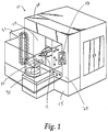
- the machine 10 has a frame 12 that supports a gantry 38 movable in a horizontal X-axis direction and slidable along an upper supporting, frame member 20 and a lower supporting, frame member 22.
- the gantry 38 carries a tool-carrying slide or saddle 56 that travels vertically in the Y-axis direction.
- the saddle 56 carries a reciprocating ram 68 and tool spindle 78 which has a tool 11 thereon for cutting a workpiece 30 mounted on a workpiece support 34.
- the gantry 38, saddle 56 and ram 68 are driven by linear motors, generally designated 108, and each having permanent magnets 110 and coil stator sections 112.
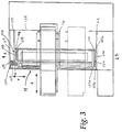
- upper and lower driving forces are applied to the upper and lower ends 38a and 38b of the gantry 38 by an upper linear motor 108b secured to the upper, horizontal frame member 20 and a lower linear motor 108a secured to the lower, horizontal frame member 22.
- the saddle 56 and the tool-carrying spindle 78 are both mounted between the upper and lower linear motors, 108b and 108a, respectively, so that there is symmetry about the spindle 78.
- This is in contrast to the asymmetrical machine disclosed in the aforesaid '425 Patent where the linear motors are all mounted at the bottom of the column and all push on the lower end of the column. In the machine 10, shown in FIGS.
- substantially equal forces from linear motors exert propelling forces at the top of the gantry 38 adjacent the upper frame member 20 and at the bottom of the gantry 38 adjacent the lower frame member 22. Because of the force application at the top and bottom of the gantry 38 on opposite sides of the spindle-carrying ram 68, the gantry 38 need not have the structural members therein to resist bending and deflecting as did the massive column of the '425 Patent, which had the tool spindle located above all of the linear motors in the machine base for driving the column in X-axis direction.
- the attractive magnetic normal force, 6,000 pounds per linear motor are offsetting in that the upper linear motor 108b pulls upwardly with a 6,000 pound force, indicated by the arrow A in FIGS. 2 and 3, and the lower linear motor 108a pulls downwardly with a 6,000 pound force as indicated by the arrow B in FIGS. 2 and 3.
- the net magnetic, normal force is preferably about zero because the upper and lower linear motors are substantially identical in size and field strength, and are controlled simultaneously in the same manner.
- all of the X-direction linear motors exerted downward forces, e.g., 24,000 pounds of downward force. This created additional frictional resistance and the need for heavier structural members in the column to resist deflection.
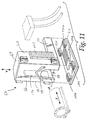
- the saddle 56 is supported on its left and right sides by vertical gantry frame members 40 and 42, each of which carries vertically-disposed portions of linear motors 108c and 108d (FIG. 10) on opposite sides of the tool-carrying spindle 78. That is, the linear motor drives are mounted on opposite sides of the spindle 78 and are symmetrical to the spindle 78 to exert equal, vertically-directed forces on opposite sides of the saddle 56.
- the saddle 56 is supported on opposite sides thereof and the propelling force in the Y-direction is applied on opposite sides of the saddle 56 by the left and right-hand linear motors 108c and 108d.
- the structure of the cantilevered spindle slide had to be strengthened by a heavy framework of ribs in order to resist bending and deflection of the spindle slide in order to provide the stiffness needed for the cutting tool on the spindle.
- the saddle 56 can be much lighter and provide a higher stiffness to mass ratio. The lighter weight saddle 56 allows faster acceleration and the use of less linear motor thrust forces.
- the spindle 78 may be mounted symmetrically with respect to the X-axis and Y-axis motors resulting in a minimum of structural deflection, an elimination of bending as experienced in cantilevered loads, and a cancellation of normal attractive, magnetic forces. While it is possible to mount linear motors both above and below the spindle 78 and on the saddle 56, it is preferred to use only a single linear motor drive located beneath the spindle 78 and to use the 6,000 lb. normal downward, attractive force to preload the ram 68 into tight engagement with the ways on the spindle.
- the square or rectangular frame receives its alignment from the steel frame members 16, 18, 20 and 22 that encompass the gantry, the saddle and the spindle-carrying ram, hereafter referred to in a group as movable members 14.
- the frame 12 is formed from steel with the height of the machine in the Y-direction as measured between the members 20 and 22 being equal to or less than the width of the machine in the X-direction, measured between members 16 and 18 to provide a very stable box-frame support for the movable members 14 as they slide along their respective axes of movement.
- the machine can be shipped, ready to install and it need not be set up and leveled on a massive foundation as was the '425 patented machine.
- vibration isolators 150 may be positioned between the bottom frame member 22 and the floor, and the machine should be ready to use without leveling or a specialized foundation therefor.
- the bottom frame member 22, as well as the rest of the frame 12 could be rotated through 90°, 180° or 270° and still perform the same because of the symmetry of the machine and because of the box-like nature of the frame.
- the ends of the ways had large bellow-shaped covers that extended beyond the ways and added significantly to the length of the machine.
- the box-shaped frame 12 is enclosed in a containment housing that is pressurized by air from a fan to keep metal dust particles and chips from the ways and from the linear magnetic motors.
- the shorter length is of particular importance where a plurality of machine tools 10 are disposed side-by-side in a transfer line.
- a vertical gantry 38 as used as the movable member 14 movable along the X-axis is illustrated.
- the vertical gantry 38 is driven for movement along the X-axis and is mounted in the frame 12 to extend between the top and bottom members, 20 and 22, thereof.
- the vertical gantry 38 includes parallel elongate side trusses 40 and 42 joined to top and bottom walls 44 and 46, respectively.
- Front and rear walls 48 and 50 are provided between the trusses 40 and 42 and top and bottom walls 44 and 46, each having elongate slots 52 and 54 therein which define the Y-axis of travel for the cutting tool 11 and allow the cutting tool 11 to be advanced therethrough along the Z-axis.
- a saddle 56 as used as the member 14 movable along the Y-axis is illustrated.
- the saddle 56 has a pair of laterally spaced, parallel sidewalls 58 and 60 each having an L-shaped profile.
- the saddle 56 is mounted for vertical sliding movement in the gantry 38 between the trusses 40 and 42.
- the gantry side-trusses 40 and 42 are spaced at a distance slightly greater than the distance between the saddle sidewalls 58 and 60 to provide a close fit between the gantry trusses 40, 42 and saddle sidewalls 58, 60 as the saddle 56 is carried by the gantry 38 and is driven for sliding movement along the Y-axis in the gantry 38.
- the saddle 56 further includes a bottom, detachable web wall 62 in the form of a flat plate which extends between the sidewalls 58 and 60.
- the top wall 64 and a forward wall 66 complete the framing for the saddle 56 and form a cradle for carrying a ram 68 as will be more fully described herein.
- the front wall 66 of the saddle 56 is cut out as at 70 to provide an arched opening 72 through which the ram 68 can extend when driven along the Z-axis.
- the saddle 56 supports the ram 68 from beneath the ram 68 eliminating the cantilever support as shown in the '425 Patent and the undue deflection stresses created thereby.
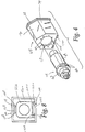
- the ram 68 includes a hollow body 76 for supporting a spindle 78 therein.
- the body 76 has an annular bore 77 extending therethrough.
- the outer surface 79 of the body 76 can have a number of different shapes when viewed in cross-section.
- the preferred polygonal shape for the ram 68 is shown in FIG. 4 as a pentagon.
- the exact shape of the pentagon itself can vary (FIG. 8), as will be more fully described herein. As seen in FIG.
- a resilient plastic wiper element 81 can be utilized with the wiper 81 having an similar cross-sectional shape as the ram 68 to closely fit around the ram outer surface 79 and limit the travel of metallic chips and dust from being carried into the internal space 13 as the ram 68 slides along the Z-axis.
- the ram 68 further includes a series of holes 86 in the front face 87 thereof around the bore 77.
- the spindle 78 has an enlarged, annular forward flange 82 formed integrally with a cylindrical body 84 extending rearwardly therefrom with the flange 82 including a series of circumferentially spaced holes 88 therethrough.
- the cylindrical body 84 has a diameter sized so that it tightly fits within the bore 77 and is fixed therein by aligning holes 86 and 88 on the ram front face 87 and spindle forward flange 82 and inserting attachment members, such as threaded bolts (not shown), through the holes.
- a ram 68a in another form, includes a hollow body 76a having a cylindrical shape surface 79a is provided as seen in FIG. 5.
- the ram 68a has an enlarged, annular front flange 80, with the annular flange 80 having an inner diameter slightly less than the diameter of the bore 77 and a series of holes 86a therearound, as best seen in FIG. 7.
- the annular flanges 80 and 82 cooperate to secure the spindle 78 in the ram 68.
- the cylindrical body 84 has a diameter slightly less than the inner diameter of the annular front flange 80 such that the spindle 78 can be fit into the ram bore 77 with the cooperating front and forward flanges 80 and 82 being secured to one another as by aligning holes 86a and 88 therein, respectively, and attaching, as previously described.
- the ram body 76a is attached to a bottom support plate 81 to mount the linear motor portion associated with the ram 68a for driving the ram 68a along the Z-axis.
- the ram 68a can be further provided with a protective "doghouse" housing 90 for guarding portions of the ram 68a which extend outwardly from the frame 12 through the opening 28 as the ram 68a is driven along the Z-axis to protect the portions of ram 68a which extend outwardly from the frame internal space 13 during sliding movement along the Z-axis. Accordingly, the wiper element 81 is not necessary when the housing 90 is employed.
- the housing 90 can have a steel roof 92 having a forward end 94 and a rearward end 96. At the forward end 94, a vertical front plate 98 is provided having an entry hole 100 centrally cut therein and of sufficient diameter such that the ram 68 can slide therethrough.
- the housing 90 can be attached to the cylindrical body 76 by connecting the bottom of the roof 92 at the forward end 94 thereof to the flange 80 as by bolting or the like.
- a peaked cut-out section as at 74 is provided above the arched opening 72 and corresponds to the shape of the roof 92 to allow it to extend therethrough as the ram 68 slides along the Z-axis.
- the slot 52 in the front wall 48 of the gantry 38 is cut so that the front plate 98 along with the bellows 102, 104 and steel roof 92 can slide therethrough.
- the front wall 66 of the saddle 56 limits the distance to which the housing 90 can extend into the saddle 56 as movement to the right in FIG. 10 is permitted until the front plate 98 of the housing 90 reaches the front wall 66 of the saddle 56.
- the expansible chamber 106 alternatively collapses and expands as the ram moves in and out of the saddle 56 along the Z-axis.
- the movable members 14 including the horizontal ram 68, the saddle 56 and the gantry 38 are all nested one within the other for three-axis movement of the tool 10. More specifically, the gantry 38 carries the saddle 56 and the ram 68 and spindle 78 along the X-axis, the saddle 56 carries the ram 68 and spindle 78 along the Y-axis, and ram 68 only carries the spindle 78 along the Z-axis.
- linear motors 108 are employed to drive the movable members 14 for three-axis movement of the tool 10.
- the linear motors 108 each have a stator coil section 110 and a row of permanent magnets 112.
- the permanent magnets 112 of the linear motor 108 are arranged in a row and are bonded to the movable members 14 and the frame 12 with spaces between magnets in a row being filled with epoxy.
- a thin strip of a protective non-magnetic, metallic material covers each row of magnets 112.
- the linear motors 108 can be any motor which operates based on attractive magnetic forces producing a thrust driving force such that there is no contact between the driving (stationary) and driven (moving) members.
- the linear motors 108 can be brushless DC motors and each may have maximum thrust force of 2,000 pounds.
- the linear motors 108 are generally positioned between the movable members 14 and the movable member in the X-axis (the gantry 38) and the frame 12.
- the control for the linear motors 108 is integrated into the machine frame 12 and is operable as by control panel 116.
- a position feedback (not shown) is utilized and can include optical, mechanical or laser sensors used to detect the position of the movable members and send signals to allow the control to energize only those coils needed to drive the member along its axis of movement, as is known in the art.
- bearing structure 118 in the form of cooperating anti-friction, elongate linear rails 120 and rail receiving trucks 122 are positioned between the movable members 14 and the movable member in the X-axis (the gantry 38) and the frame 12 to support and guide sliding movement thereof in the X, Y and Z-axes as they are driven by the linear motors 108.
- the rails 120 and trucks 122 provide their guiding and supporting functions through roller or ball bearings, or through surfaces coated with low coefficient of friction materials, such as Teflon.
- the box frame internal space 13 can be divided into front and rear regions 126 and 136, respectively, by an intermediate partition wall 124 which extends between the side members 16 and 18.
- the front frame panel 24 can be attached to a T-shaped base 15 for the box frame 12 at the junction of the arm and leg of the "T" and extends upwardly from the base and is attached to the machining housing 32 for the support 34 about the rear thereof.
- the panel 24 extends parallel to the intermediate wall 124 and has a central, rectangular-shape cut out 26 to fit around the housing 32 and to allow the ram 68 to extend into the housing 32 along the Z-axis to engage a workpiece 30 therein.
- the intermediate partition wall 124 along with the side members 16 and 18, front panel 24 and the top and bottom members 20 and 22 define a front gantry region 126 in the box frame internal space 13.
- the intermediate partition wall 124 has a rectangular shaped cut-out section therein which allows for the bottom leg 130 of the L-shaped side walls 58 and 60 of the saddle 56 to extend therethrough during movement of the saddle along the Y-axis, and allows the ram 68 to extend therethrough as the ram 68 moves along the Z-axis.
- Two parallel side support panels 132 and 134 can be spaced inwardly from the box frame side members 16 and 18, respectively, and extend from the intermediate partition wall 124 towards the rear of the box frame 12.
- the intermediate partition wall 124, the side panels 132 and 134 and the top and bottom members 20 and 22 cooperatively define the rear region 136 in the box frame internal space 13 into which the saddle bottom legs 130 and ram 68 can project, as previously described.
- the rear region 136 provides an enclosure for housing the various services and support equipment, such as a tank, pump and chiller, for supplying the linear motors with cooling water.
- the box frame 12 can be sealed at the forward central opening 28 thereof as by structure for blocking the opening while allowing the ram 68 to extend therethrough during its sliding movement along the Z-axis.
- the sealing structure can take the form of X and Y-curtains 142 or baffles which allow the saddle 38 and ram 68 to move in the X and Y-axes while still blocking the opening 28 around the ram 68.
- the curtain 142 includes an upper curtain roll 142a above the saddle and a lower curtain roll 142b at the bottom of the frame and below the saddle. The upper and lower curtains roll and unroll respectively as the saddle moves vertically.
- the rear of the machine can be sealed by sheet metal to complete the rear region enclosure.
- the box frame internal space 13 can be pressurized by a positive pressure means in the form of a fan 146 to prevent dust and workpiece chips generated during a machining operation from entering the internal space.
- the fan 146 can be placed in the box frame rear region 136 and supplied with ambient filtered air.
- the pressurized air from the fan 146 can effectively isolate the internal space from any cast-iron or steel dust or chips generated from the workpiece which might be attracted to the magnetics of the linear motors 108 which could adversely affect operation of the same.
- the base 15 as described earlier can be removed while providing the frame 12 with a thicker bottom member 22a which is directly mounted to a support surface.
- Vibration-absorbing resilient pads 150 can be attached to the bottom frame member 22a to isolate the machine and the support surface one from the other so that vibrations in either are not transmitted from one to the other. Because of the symmetrical box-frame construction of the machine, the alignment of the machine does not depend upon the foundation such that only three support pads 150 need be utilized to provide the machine with an effective three-point mounting to the support surface.
- a pair of opposed linear motors 108a and 108b are provided, as seen in FIG. 3.
- the deflection loads caused by driving the gantry solely from the bottom is substantially obviated.
- the bottom driving of the long freestanding column causes a deflection near the free top end of the column due to the concentration of drive forces at the bottom of the column thereby causing a deflection lag at the top as the column is driven.
- the coil stator section 112a of the bottom gantry linear motor 108a is mounted on the gantry bottom member 46 while the row of permanent magnets 110a is mounted along the X-axis on the bottom frame member 22 in the front gantry region 126 (FIG. 12).
- Adjacent the coil stator section 112a mounted on the frame bottom member 22 are a pair of linearly aligned rail-receiving trucks 122a (FIG. 10). Aligned therewith is a slide rail 120a positioned adjacent the magnets 110a so that the gantry 38 is supported and guided for sliding movement along the X-axis by the cooperating rail and trucks, 120a and 122a, respectively.
- the top linear motor 108b is positioned at or near the top of the gantry 38 and frame 12.
- a horizontally extending frame member 154 is provided in the front gantry region 126 parallel and spaced from the top frame member 20.
- the frame member 154 extends from the intermediate wall 124 towards the front of the frame 12 and is attached to a vertical wall portion 158 between the front panel 24 and intermediate wall 124 extending between the wall portion 154 and the top frame member 20.
- the coil stator section 112b is mounted to the gantry top wall 44 and the row of permanent magnets 110b is aligned therewith along the X-axis and is mounted to the bottom of the horizontal wall portion 154.
- a rail 120b and trucks 122b are provided to guide and support the gantry 38 near the top thereof as it is advanced along the X-axis.
- the gantry 38 includes a vertical flange 162 mounting the linearly arranged pair of trucks 122b (FIG. 10).
- the vertical wall portion 158 of the frame 12 mounts the slide rail 120b such that it is in alignment with the trucks 122b for sliding movement therein.
- both the trucks 122b and the coil section 112b are mounted in side-by-side relation on the gantry top wall 44 with the rail 120b and row of permanent magnets 110b being aligned therewith mounted on the top frame member 20, as illustrated in FIG. 13.
- the arrangement of the cooperating rail 120b and trucks 122b and the linear motor 108b can be altered, such as by placement thereof on the intermediate wall 124, as long as they remain near the top of the gantry to provide for top driving of the same.
- the attractive magnet force in the top and bottom linear motors 108a and 108b are self-canceling so as to limit structural deflections as caused by the unbalanced magnetic forces as applied in the machine of the '425 Patent.
- linear motors 108c and 108d can be positioned between the saddle sidewalls 58 and 60 and the gantry side trusses 40 and 42, respectively, to balance the magnetic forces applied between the gantry 38 and saddle 56 about the Y-axis. More specifically, each gantry side truss 40 and 42 mounts one-half of the linear motors 108c and 108d, respectively, which in the preferred form is a row of permanent magnets 112c and 112d extending along the Y-axis (FIG. 10).
- the respective coil stator sections 112c and 112d are mounted on the saddle sidewalls 58 and 60, respectively, to drive the saddle 56 and the ram 68 carried thereby along the Y-axis.
- the saddle 56 is symmetrically driven from either side thereof about the Y-axis while simultaneously providing a support beneath the ram 68 in the form of the detachable web wall 62, thereby eliminating any overhung or cantilevered loads as seen with the ram, slide and column configuration in the '425 Patent.
- a pair of counterbalance cylinders 166 and 168 are attached between the gantry 38 and the saddle 56 such that when the linear motors 108c and 108d are not activated, the saddle 56 remains stationary in the gantry 38 along the Y-axis.
- the cylinders 166 and 168 can be, for example, either air or hydraulic cylinders and each include a spring brake 170 and 172, respectively, as is known in the art.
- the spring brakes 170 and 172 are activated to maintain the saddle 56 in position along the Y-axis.
- the saddle 56 includes a detachable bottom web wall 62 for providing the ram 68 with a cradle or support thereunder as it slides along the Z-axis.
- the web wall 62 can be attached to the main portion of the saddle 56, as seen in FIG. 11, by any variety of well-known attaching means such as by threaded holes and bolts which also allows the web wall 62 to be adjustable so as to correct for any variations in tolerances between the ram 68 and saddle 56.
- the coil stator section 112e is mounted on the bottom web wall 62 with a pair of linearly arranged trucks 122e positioned on either side thereof.
- a row of permanent magnets 110e is mounted beneath the ram 68 and is flanked by two parallel rails 120e with the magnets 110e and rails 120e being aligned with the coils 112e and the trucks 122e, respectively, to allow the ram 68 to be driven for sliding movement along the Z-axis and supported by the web wall 62.
- the strong attractive force provided by the linear motor 108e produces a preload on the rails 120e and trucks 122e to provide the spindle 78 with greater stability as the ram 68 is reciprocated along the Z-axis.
- the movable elements 14, i.e., the gantry 38, the saddle 56 and the ram 68 can all be relatively light in weight and still be formed from a material having a high degree of material stiffness, such as steel, to be accurately driven for high-speed movement by their respective linear motors 108 so that the tool 10 can be advanced at speeds of at least 1500 inches per minute and at an acceleration or deceleration of at least 1G.
- balanced magnetic drive forces are applied to the ram 68 by utilizing a slightly modified pentagonal shape, as illustrated in FIG. 8, wherein the flat top surface thereof is extended in the X-direction so that it is adapted to mount a row of permanent magnets 110f thereon.
- the modified ram 68b utilizing a top mounted linear motor 108f also employs a slightly modified saddle construction wherein the saddle 56a forms a square-shaped frame about the circumference of the ram 68b so that the top horizontal member 174 of the saddle 56a can mount a coil pack 112f thereon in alignment with the magnets 110f to drive the ram 68b from both the top and bottom thereof.
- linear motors 108 in the box-frame machine tool described herein provides for flexibility in the design of its movable members 14 as the linear motors 108, unlike conventional ball-screw motors or the linear motors in the machine of the '425 Patent, can be distributed throughout the machine tool box-frame 12 to balance forces about the various axes of movement.
- the exact placement of the motors 108 and their components, i.e., the magnets 110 and coil section 112 can be varied in accordance with the force and load balancing principles described herein.
- improved accuracy, stiffness, speed and acceleration can be obtained over conventional machine tools.
Priority Applications (1)
| Application Number | Priority Date | Filing Date | Title |
|---|---|---|---|
| DE29522019U DE29522019U1 (de) | 1995-05-12 | 1995-11-24 | Symmetrische Vielachsen-Linearmotor-Werkzeugmaschine |
Applications Claiming Priority (2)
| Application Number | Priority Date | Filing Date | Title |
|---|---|---|---|
| US08/440,416 US5662568A (en) | 1995-05-12 | 1995-05-12 | Symmetrical multi-axis linear motor machine tool |
| US440416 | 1995-05-12 |
Publications (3)
| Publication Number | Publication Date |
|---|---|
| EP0742072A2 true EP0742072A2 (de) | 1996-11-13 |
| EP0742072A3 EP0742072A3 (de) | 1996-11-27 |
| EP0742072B1 EP0742072B1 (de) | 2000-04-05 |
Family
ID=23748684
Family Applications (1)
| Application Number | Title | Priority Date | Filing Date |
|---|---|---|---|
| EP95118569A Revoked EP0742072B1 (de) | 1995-05-12 | 1995-11-24 | Symmetrische, mehrachsige, mit Linearmotoren versehene Werkzeugmaschine |
Country Status (5)
| Country | Link |
|---|---|
| US (3) | US5662568A (de) |
| EP (1) | EP0742072B1 (de) |
| JP (1) | JPH08318445A (de) |
| CN (1) | CN1086975C (de) |
| DE (2) | DE69516120T2 (de) |
Cited By (16)
| Publication number | Priority date | Publication date | Assignee | Title |
|---|---|---|---|---|
| EP0893196A2 (de) * | 1997-07-24 | 1999-01-27 | Toyoda Koki Kabushiki Kaisha | Werkzeugmaschine |
| WO1999006176A2 (de) * | 1997-07-29 | 1999-02-11 | Ex-Cell-O Gmbh | Werkzeugmaschine |
| ES2157159A1 (es) * | 1999-05-20 | 2001-08-01 | D & S Sist S S Coop | Centro de mecanizado de husillo horizontal y de gran velocidad |
| EP0985489A3 (de) * | 1998-09-10 | 2001-11-14 | Toyoda Koki Kabushiki Kaisha | Maschine mit zwei Spindelköpfen und Abdeckvorrichtung dafür |
| EP1182004A1 (de) * | 2000-08-21 | 2002-02-27 | Ministero Dell' Universita' E Della Ricerca Scientifica E Tecnologica | Hochgeschwindigheitsherstellungseinheit für Bearbeitungsvorgänge |
| DE10039915A1 (de) * | 2000-08-16 | 2002-02-28 | Schaeffler Waelzlager Ohg | Linearführung |
| WO2002032619A1 (de) * | 2000-10-09 | 2002-04-25 | Honsberg Lamb Sonderwerkzeugmaschinen Gmbh | Werkzeugmaschine |
| US6661126B2 (en) | 2000-08-16 | 2003-12-09 | Ina-Schaeffler Kg | Linear guide |
| EP0876240B2 (de) † | 1996-01-23 | 2004-08-18 | Comau Systemes France S.A. | hochgeschwindigkeitswerkzeugmaschine mit spindelträger |
| EP1477267A2 (de) * | 2003-05-14 | 2004-11-17 | Toyoda Koki Kabushiki Kaisha | Werkzeugmaschine mit linearmotoren |
| EP1238752B1 (de) * | 2001-03-09 | 2005-06-01 | Cross Hüller GmbH | Werkzeugmaschine |
| EP1588796A2 (de) * | 2004-04-23 | 2005-10-26 | Aerotech, Inc. | Hochpräzisionshaltevorrichtung |
| US7008152B2 (en) | 2000-06-29 | 2006-03-07 | Cross Hüller GmbH | Machine tool for processing work pieces on at least three axes |
| WO2014086621A1 (de) * | 2012-12-04 | 2014-06-12 | Ops-Ingersoll Funkenerosion Gmbh | Hochdynamische kleinmaschine |
| EP2813318A1 (de) * | 2013-06-14 | 2014-12-17 | Schwäbische Werkzeugmaschinen GmbH | Werkzeugmaschine mit kompensiertem Werkzeugdurchhang und einstellbarem Werkzeugsturz |
| US9545677B2 (en) | 2014-03-06 | 2017-01-17 | O.M.V. Officine Meccaniche Venete S.P.A. | Numerical control machine-tool |
Families Citing this family (68)
| Publication number | Priority date | Publication date | Assignee | Title |
|---|---|---|---|---|
| DE19503482C2 (de) * | 1995-02-03 | 1996-12-05 | Honsberg Gmbh Geb | Werkzeugmaschine mit einem Ständer, an dem zwei Spindelstöcke unabhängig voneinander verfahrbar sind |
| US5854460A (en) * | 1996-05-07 | 1998-12-29 | Cincinnati Incorporated | Linear motor driven laser cutting machine |
| DE19639527C1 (de) * | 1996-09-26 | 1998-04-09 | Hueller Hille Gmbh | Werkzeugmaschine zur spanenden Bearbeitung mit horizontal angeordneter Arbeitsspindel |
| DE19745233B4 (de) * | 1996-10-19 | 2006-02-16 | Horkos Corp., Fukuyama | Spindel-Halterungskasteneinrichtung für Werkzeugmaschinen |
| JPH10263960A (ja) * | 1997-03-19 | 1998-10-06 | Mori Seiki Co Ltd | 工作機械 |
| JP3847437B2 (ja) * | 1998-02-04 | 2006-11-22 | 株式会社ジェイテクト | リニアモータ駆動式工作機械 |
| DE69825828T2 (de) * | 1997-09-30 | 2005-09-01 | Toyoda Koki K.K., Kariya | Horizontal-Werkzeugmaschine |
| FR2771324B1 (fr) * | 1997-11-27 | 2000-02-18 | Renault Automation | Procede d'allongement de la course d'usinage d'une machine-outil, dispositif permettant de le mettre en oeuvre et machine-outil utilisant un tel dispositif |
| US6120223A (en) * | 1998-09-03 | 2000-09-19 | Howa Machinery, Ltd. | Cover device for machine tool |
| GB2348385B (en) * | 1998-11-24 | 2002-12-24 | Honda Motor Co Ltd | Machining centre, contouring process and tool supporting mechanism, tool changer, curvic coupling device, and pallet changer in machine tool. |
| WO2000076704A1 (en) * | 1999-06-11 | 2000-12-21 | Unova I.P. Corporation | Machine tool drive system |
| JP3256879B2 (ja) * | 1999-07-01 | 2002-02-18 | ホーコス株式会社 | 工作機械 |
| JP3168328B2 (ja) * | 1999-07-12 | 2001-05-21 | ホーコス株式会社 | 工作機械及び、そのカバー装置 |
| FR2801823B1 (fr) * | 1999-09-07 | 2002-02-15 | Renault Automation Comau | Machine-outil d'usinage de type bibroche |
| DE19951234B4 (de) * | 1999-10-25 | 2005-02-10 | Helmut Unterberg | Vorrichtung zur Stabilisierung und Schwingungsdämpfung eines Frässchiebers |
| DE69914377T2 (de) * | 1999-11-19 | 2004-11-04 | Makino Milling Machine Co. Ltd. | Numerisch gesteuerte werkzeugmaschine |
| DE19963342A1 (de) * | 1999-12-27 | 2001-06-28 | Grob Gmbh & Co Kg | Werkzeugmaschine |
| WO2001051247A1 (de) * | 2000-01-07 | 2001-07-19 | Deckel Maho Seebach Gmbh | Fräsmaschine mit rotierend antreibbarer werkzeugspindel |
| JP3353083B2 (ja) * | 2000-05-10 | 2002-12-03 | ホーコス株式会社 | コラム固定形工作機械 |
| WO2001094070A1 (fr) * | 2000-06-09 | 2001-12-13 | Makino Milling Machine Co., Ltd. | Dispositif de machine-outil et procede de remplacement de la palette dudit dispositif |
| ITBO20000516A1 (it) * | 2000-09-06 | 2002-03-06 | Jobs Spa | Macchina utensile |
| EP1186371A1 (de) * | 2000-09-08 | 2002-03-13 | Mikron Comp-Tec AG | Portalfräsmaschine |
| DE60121600T2 (de) * | 2000-10-03 | 2007-06-21 | Camozzi Machine Tools S.P.A. | Mehrachsige werkzeugmaschine mit linearmotoren |
| JP3945148B2 (ja) * | 2000-11-02 | 2007-07-18 | 株式会社日立製作所 | Xyテーブル及びxyzテーブル |
| JP3907989B2 (ja) * | 2001-09-28 | 2007-04-18 | 東芝機械株式会社 | 主軸頭重心補正装置 |
| JP2003145374A (ja) | 2001-11-15 | 2003-05-20 | Mitsubishi Heavy Ind Ltd | 工作機械 |
| US6591757B1 (en) * | 2001-12-26 | 2003-07-15 | Anorad Corporation | Motor driven high stability brake for linear motion systems |
| DE10218039A1 (de) * | 2002-04-23 | 2003-11-13 | Zeiss Carl | Bearbeitungskopf zur Oberflächenbearbeitung |
| DE50300464D1 (de) * | 2003-02-26 | 2005-05-25 | Felsomat Gmbh & Co Kg | Grundgestell für eine Handhabungsvorrichtung und Handhabungsvorrichtung |
| JP4234514B2 (ja) * | 2003-07-09 | 2009-03-04 | 株式会社森精機製作所 | Nc旋盤 |
| DE102004007472A1 (de) * | 2004-02-13 | 2005-09-01 | Grob-Werke Burkhart Grob E.K. | Werkzeugmaschine mit einem Spindelstock |
| WO2005110898A2 (en) | 2004-05-07 | 2005-11-24 | Magnemotion, Inc. | Three-dimensional motion using single-pathway based actuators |
| US7571022B2 (en) * | 2004-10-25 | 2009-08-04 | Ford Motor Company | System and method for monitoring machine health |
| US7383097B2 (en) * | 2004-10-25 | 2008-06-03 | Ford Motor Company | Method for managing machine tool data |
| US7409261B2 (en) * | 2004-10-25 | 2008-08-05 | Ford Motor Company | Data management and networking system and method |
| US20070088454A1 (en) * | 2004-10-25 | 2007-04-19 | Ford Motor Company | System and method for troubleshooting a machine |
| ITBO20050021A1 (it) * | 2005-01-17 | 2006-07-18 | Jobs Spa | Macchina utensile pluriasse |
| JP4410140B2 (ja) * | 2005-04-06 | 2010-02-03 | 株式会社森精機製作所 | 工作機械 |
| US20070204473A1 (en) * | 2006-03-03 | 2007-09-06 | Honda Motor Co., Ltd. | Spindle locating laser for nut runner |
| US8066548B1 (en) | 2006-10-19 | 2011-11-29 | Max-Tek, LLC | Multi-axes contouring machine and method of use |
| US7534078B1 (en) * | 2008-04-22 | 2009-05-19 | Cincinnati Machine, Llc | Consistent rigidity construction arrangement for a machine tool |
| US8616134B2 (en) | 2009-01-23 | 2013-12-31 | Magnemotion, Inc. | Transport system powered by short block linear synchronous motors |
| US9032880B2 (en) | 2009-01-23 | 2015-05-19 | Magnemotion, Inc. | Transport system powered by short block linear synchronous motors and switching mechanism |
| DE102009031202A1 (de) * | 2009-06-29 | 2010-12-30 | Grob-Werke Gmbh & Co. Kg | Werkzeugmaschine mit einer Werkzeugwechselvorrichtung |
| WO2011062177A1 (ja) * | 2009-11-18 | 2011-05-26 | コマツNtc株式会社 | ツールマガジンおよびマシニングセンタ |
| CN101905422B (zh) * | 2010-08-04 | 2012-06-13 | 无锡中盈实业有限公司 | 镗铣床方滑枕结构 |
| US8662802B2 (en) | 2011-03-04 | 2014-03-04 | Fives Machining Systems, Inc. | High rigidity moving column horizontal machine tool |
| TW201304898A (zh) * | 2011-07-25 | 2013-02-01 | Chuan-Zhou Cao | 多軸工具機 |
| CN102950471A (zh) * | 2011-08-17 | 2013-03-06 | 曹传周 | 多轴工具机 |
| US20140319746A1 (en) * | 2011-12-22 | 2014-10-30 | Murata Machinery, Ltd. | Machine tool |
| CN103567799B (zh) * | 2012-07-20 | 2016-08-03 | 鸿准精密模具(昆山)有限公司 | 进给装置及应用该进给装置的机床 |
| CN102794473A (zh) * | 2012-07-30 | 2012-11-28 | 林淑琴 | 一种滑动式钻眼机 |
| JP6156877B2 (ja) * | 2012-10-16 | 2017-07-05 | ホーコス株式会社 | 工作機械 |
| CN106329815B (zh) * | 2012-10-17 | 2018-11-16 | 上海交通大学 | 基于永磁体和电磁体相互作用的位移驱动装置 |
| CN105813886B (zh) | 2013-09-21 | 2018-04-03 | 麦克纳莫绅有限公司 | 用于包装和其它用途的线性电机运输 |
| DE202014007224U1 (de) * | 2014-09-11 | 2015-12-14 | Sauer Gmbh | Werkzeugmaschine |
| US9512896B2 (en) | 2014-12-29 | 2016-12-06 | General Electric Company | Reducing vibration of a cantilevered patient support surface |
| CN105983878B (zh) * | 2015-03-06 | 2019-03-01 | 东莞市迪奥数控设备有限公司 | 一种全罩刀库机的开门装置 |
| CN105619181A (zh) * | 2015-06-16 | 2016-06-01 | 深圳市万嘉科技有限公司 | 加工设备 |
| JP6570964B2 (ja) * | 2015-10-23 | 2019-09-04 | 株式会社ディスコ | 筒状蛇腹カバー |
| WO2019222143A1 (en) * | 2018-05-14 | 2019-11-21 | Modig Machine Tool US Inc. | Invertible part loading system |
| KR20220044506A (ko) * | 2019-07-05 | 2022-04-08 | 무어 나노테크놀러지 시스템즈, 엘엘씨 | 정밀 지그 연삭 공정 중 가공오차 보정 시스템 및 방법 |
| CN110480046A (zh) * | 2019-07-24 | 2019-11-22 | 高邮市永发机械有限公司 | 一种便于收集铁屑且防护效果好的台式钻床 |
| TWI726498B (zh) * | 2019-11-22 | 2021-05-01 | 財團法人工業技術研究院 | 龍門機構線上慣量匹配同步控制方法 |
| US11161233B2 (en) * | 2020-01-16 | 2021-11-02 | North Mechanical Contracting Inc. | Vertical drill mount |
| CN111604526A (zh) * | 2020-06-03 | 2020-09-01 | 赵永伟 | 一种数控轻型铣床 |
| CN111408956B (zh) * | 2020-06-08 | 2020-09-08 | 佛山市南海富大精密机械有限公司 | 一种直线电机驱动的四轴联动数控机床 |
| CN113681345A (zh) * | 2021-09-28 | 2021-11-23 | 黑马赵防护技术(青岛)有限公司 | 高速运行壁式防护系统 |
Citations (1)
| Publication number | Priority date | Publication date | Assignee | Title |
|---|---|---|---|---|
| US5368425A (en) | 1992-07-31 | 1994-11-29 | Ford Motor Company | Multi-axis linear motor positioner with Y-axis supported at single end |
Family Cites Families (31)
| Publication number | Priority date | Publication date | Assignee | Title |
|---|---|---|---|---|
| US31288A (en) * | 1861-02-05 | Tuning-peg | ||
| JPS5444870Y2 (de) * | 1975-06-19 | 1979-12-22 | ||
| US4118844A (en) * | 1976-08-30 | 1978-10-10 | Kabushiki Kaisha Komatsu Seisakusho | Machine tool |
| US4102035A (en) * | 1977-04-25 | 1978-07-25 | Ex-Cell-O Corporation | Machining center with automatic tool changer |
| SU729005A1 (ru) * | 1978-01-04 | 1980-04-28 | Горьковский политехнический институт им.А.А.Жданова | Металлорежущий станок |
| JPS57145645U (de) * | 1981-03-05 | 1982-09-13 | ||
| US4505464A (en) * | 1983-03-28 | 1985-03-19 | Anorad Corporation | High precision workpiece positioning table |
| JPS606322A (ja) * | 1983-06-27 | 1985-01-14 | Hitachi Ltd | 門形移動体移動装置 |
| JPS60167729A (ja) * | 1984-02-09 | 1985-08-31 | Teijin Seiki Co Ltd | 工作機械 |
| JPS61109637A (ja) * | 1984-10-31 | 1986-05-28 | Hitachi Ltd | テ−ブル装置 |
| DE3506314A1 (de) * | 1985-02-22 | 1986-08-28 | Kuka Schweissanlagen + Roboter Gmbh, 8900 Augsburg | Verfahren und vorrichtung zum automatischen fuegen und bearbeiten |
| DE3523013A1 (de) * | 1985-06-27 | 1987-01-02 | Schaudt Maschinenbau Gmbh | Schleifmaschine |
| JPS6263033A (ja) * | 1985-09-11 | 1987-03-19 | Kitamura Kikai Kk | 多面加工装置 |
| US4761876A (en) * | 1986-04-18 | 1988-08-09 | Dynamotion Corporation | High speed precision drilling system |
| JPS63283847A (ja) * | 1987-05-14 | 1988-11-21 | Kiyoueki Eng Kk | 工作機械 |
| US4834353A (en) * | 1987-10-19 | 1989-05-30 | Anwar Chitayat | Linear motor with magnetic bearing preload |
| US4985651A (en) * | 1987-10-19 | 1991-01-15 | Anwar Chitayat | Linear motor with magnetic bearing preload |
| US4890241A (en) * | 1987-10-26 | 1989-12-26 | Megamation Incorporated | Robotic system |
| US4916340A (en) * | 1988-01-22 | 1990-04-10 | Canon Kabushiki Kaisha | Movement guiding mechanism |
| US4895651A (en) * | 1988-02-01 | 1990-01-23 | Niddleton Glen H | Personal, portable, disposable tap water filter |
| CH677746A5 (de) * | 1989-01-25 | 1991-06-28 | Dixi Sa | |
| FR2652291B1 (fr) * | 1989-09-27 | 1992-01-10 | Helis | Machine d'usinage a montant mobile et a broche horizontale. |
| JP3031940B2 (ja) * | 1990-02-21 | 2000-04-10 | キヤノン株式会社 | 移動案内装置 |
| DE4012690A1 (de) * | 1990-04-20 | 1991-10-24 | Maho Ag | Bearbeitungszentrum |
| IT223485Z2 (it) * | 1990-09-11 | 1995-07-20 | Jobs Spa | Macchina utensile cabinata, con struttura portante monoscocca. |
| US5401128A (en) * | 1991-08-26 | 1995-03-28 | Ingersoll Milling Machine Company | Octahedral machine with a hexapodal triangular servostrut section |
| JP2519938Y2 (ja) * | 1991-09-10 | 1996-12-11 | 株式会社アルプスツール | ツールヘッド |
| US5321874A (en) * | 1992-07-31 | 1994-06-21 | Ford Motor Company | Multi-positioner machining system |
| US5346345A (en) * | 1992-07-31 | 1994-09-13 | Ford Motor Company | High-force linear motor assembly using tandem axes |
| US5314397A (en) * | 1992-07-31 | 1994-05-24 | Ford Motor Company | Positioning apparatus for multiple-spindle machining |
| DE4307482A1 (de) * | 1993-03-10 | 1994-09-22 | Max Rhodius Gmbh | Werkzeugmaschine |
-
1995
- 1995-05-12 US US08/440,416 patent/US5662568A/en not_active Expired - Lifetime
- 1995-11-24 EP EP95118569A patent/EP0742072B1/de not_active Revoked
- 1995-11-24 DE DE69516120T patent/DE69516120T2/de not_active Expired - Fee Related
- 1995-11-24 DE DE0742072T patent/DE742072T1/de active Pending
- 1995-12-11 JP JP7321494A patent/JPH08318445A/ja active Pending
- 1995-12-12 CN CN95121419A patent/CN1086975C/zh not_active Expired - Fee Related
-
1997
- 1997-08-29 US US08/920,823 patent/US5938577A/en not_active Expired - Lifetime
-
1999
- 1999-08-12 US US09/372,926 patent/US6217496B1/en not_active Expired - Lifetime
Patent Citations (1)
| Publication number | Priority date | Publication date | Assignee | Title |
|---|---|---|---|---|
| US5368425A (en) | 1992-07-31 | 1994-11-29 | Ford Motor Company | Multi-axis linear motor positioner with Y-axis supported at single end |
Cited By (24)
| Publication number | Priority date | Publication date | Assignee | Title |
|---|---|---|---|---|
| EP0876240B2 (de) † | 1996-01-23 | 2004-08-18 | Comau Systemes France S.A. | hochgeschwindigkeitswerkzeugmaschine mit spindelträger |
| EP1402994A2 (de) * | 1997-07-24 | 2004-03-31 | Toyoda Koki Kabushiki Kaisha | Werkzeugmaschine |
| EP0893196A3 (de) * | 1997-07-24 | 1999-12-29 | Toyoda Koki Kabushiki Kaisha | Werkzeugmaschine |
| US6161995A (en) * | 1997-07-24 | 2000-12-19 | Toyoda Koki Kabushiki Kaisha | Machine tool |
| EP1402994A3 (de) * | 1997-07-24 | 2005-05-25 | Toyoda Koki Kabushiki Kaisha | Werkzeugmaschine |
| EP0893196A2 (de) * | 1997-07-24 | 1999-01-27 | Toyoda Koki Kabushiki Kaisha | Werkzeugmaschine |
| WO1999006176A2 (de) * | 1997-07-29 | 1999-02-11 | Ex-Cell-O Gmbh | Werkzeugmaschine |
| WO1999006176A3 (de) * | 1997-07-29 | 1999-04-22 | Ex Cell O Gmbh | Werkzeugmaschine |
| EP0985489A3 (de) * | 1998-09-10 | 2001-11-14 | Toyoda Koki Kabushiki Kaisha | Maschine mit zwei Spindelköpfen und Abdeckvorrichtung dafür |
| ES2157159A1 (es) * | 1999-05-20 | 2001-08-01 | D & S Sist S S Coop | Centro de mecanizado de husillo horizontal y de gran velocidad |
| US7008152B2 (en) | 2000-06-29 | 2006-03-07 | Cross Hüller GmbH | Machine tool for processing work pieces on at least three axes |
| DE10039915A1 (de) * | 2000-08-16 | 2002-02-28 | Schaeffler Waelzlager Ohg | Linearführung |
| US6661126B2 (en) | 2000-08-16 | 2003-12-09 | Ina-Schaeffler Kg | Linear guide |
| EP1182004A1 (de) * | 2000-08-21 | 2002-02-27 | Ministero Dell' Universita' E Della Ricerca Scientifica E Tecnologica | Hochgeschwindigheitsherstellungseinheit für Bearbeitungsvorgänge |
| WO2002032619A1 (de) * | 2000-10-09 | 2002-04-25 | Honsberg Lamb Sonderwerkzeugmaschinen Gmbh | Werkzeugmaschine |
| EP1238752B1 (de) * | 2001-03-09 | 2005-06-01 | Cross Hüller GmbH | Werkzeugmaschine |
| US7220090B2 (en) | 2003-05-14 | 2007-05-22 | Toyoda Koki Kabushiki Kaisha | Linear motor operated machine tool |
| EP1477267A3 (de) * | 2003-05-14 | 2004-12-22 | Toyoda Koki Kabushiki Kaisha | Werkzeugmaschine mit linearmotoren |
| EP1477267A2 (de) * | 2003-05-14 | 2004-11-17 | Toyoda Koki Kabushiki Kaisha | Werkzeugmaschine mit linearmotoren |
| EP1588796A2 (de) * | 2004-04-23 | 2005-10-26 | Aerotech, Inc. | Hochpräzisionshaltevorrichtung |
| EP1588796A3 (de) * | 2004-04-23 | 2006-12-06 | Aerotech, Inc. | Hochpräzisionshaltevorrichtung |
| WO2014086621A1 (de) * | 2012-12-04 | 2014-06-12 | Ops-Ingersoll Funkenerosion Gmbh | Hochdynamische kleinmaschine |
| EP2813318A1 (de) * | 2013-06-14 | 2014-12-17 | Schwäbische Werkzeugmaschinen GmbH | Werkzeugmaschine mit kompensiertem Werkzeugdurchhang und einstellbarem Werkzeugsturz |
| US9545677B2 (en) | 2014-03-06 | 2017-01-17 | O.M.V. Officine Meccaniche Venete S.P.A. | Numerical control machine-tool |
Also Published As
| Publication number | Publication date |
|---|---|
| US6217496B1 (en) | 2001-04-17 |
| DE69516120T2 (de) | 2000-09-28 |
| US5938577A (en) | 1999-08-17 |
| US5662568A (en) | 1997-09-02 |
| DE69516120D1 (de) | 2000-05-11 |
| CN1086975C (zh) | 2002-07-03 |
| JPH08318445A (ja) | 1996-12-03 |
| EP0742072B1 (de) | 2000-04-05 |
| CN1135950A (zh) | 1996-11-20 |
| EP0742072A3 (de) | 1996-11-27 |
| DE742072T1 (de) | 1998-04-30 |
Similar Documents
| Publication | Publication Date | Title |
|---|---|---|
| US5938577A (en) | Symmetrical multi-axis linear motor machine tool | |
| US5368425A (en) | Multi-axis linear motor positioner with Y-axis supported at single end | |
| CA2316570C (en) | High-speed production unit for machining operations | |
| US6068431A (en) | Machine tool having a gantry and a vertical spindle | |
| EP1207006A1 (de) | Wekzeugmaschine | |
| JP2718694B2 (ja) | 案内装置 | |
| JPH1058252A (ja) | 工作機械 | |
| JPH06155203A (ja) | 多重スピンドル機械加工装置のための位置決め装置及び加工方法 | |
| US6254075B1 (en) | Table feed mechanism for machine tool | |
| US20040077470A1 (en) | Multi-axis linear motor machine tool | |
| KR940006698A (ko) | 공작 기계용 프레임 | |
| CN209903604U (zh) | 一种固定三轴叠加直线电机驱动机床 | |
| EP0583087B1 (de) | Hochbelastbare Linear-Motor-Einheit, ausgestattet mit Tandem-Achsen | |
| JPH10263960A (ja) | 工作機械 | |
| CN102109766B (zh) | 解耦机构及使用所述解耦机构的曝光台 | |
| JP3532525B2 (ja) | 六脚工作機械 | |
| CN102015200B (zh) | 机床的一致性刚性构造布置 | |
| JP2007075902A (ja) | 工作機械の軸送り装置 | |
| EP0792005A1 (de) | Zufuhrvorrichtung mit linearmotorantrieb | |
| JP4084109B2 (ja) | 移動体駆動装置 | |
| RU2244617C1 (ru) | Координатный стол (варианты) | |
| KR100729473B1 (ko) | 3축집적구조를 갖는 머시닝센터 | |
| GB2295976A (en) | Method of machining aluminium-based components | |
| JP3657905B2 (ja) | 放電加工の送り装置 | |
| JP3542508B2 (ja) | 放電加工の送り機構 |
Legal Events
| Date | Code | Title | Description |
|---|---|---|---|
| PUAI | Public reference made under article 153(3) epc to a published international application that has entered the european phase |
Free format text: ORIGINAL CODE: 0009012 |
|
| PUAL | Search report despatched |
Free format text: ORIGINAL CODE: 0009013 |
|
| AK | Designated contracting states |
Kind code of ref document: A2 Designated state(s): DE FR GB IT |
|
| AK | Designated contracting states |
Kind code of ref document: A3 Designated state(s): DE FR GB IT |
|
| 17P | Request for examination filed |
Effective date: 19970114 |
|
| DET | De: translation of patent claims | ||
| 17Q | First examination report despatched |
Effective date: 19980728 |
|
| EL | Fr: translation of claims filed | ||
| GRAG | Despatch of communication of intention to grant |
Free format text: ORIGINAL CODE: EPIDOS AGRA |
|
| GRAG | Despatch of communication of intention to grant |
Free format text: ORIGINAL CODE: EPIDOS AGRA |
|
| GRAG | Despatch of communication of intention to grant |
Free format text: ORIGINAL CODE: EPIDOS AGRA |
|
| GRAH | Despatch of communication of intention to grant a patent |
Free format text: ORIGINAL CODE: EPIDOS IGRA |
|
| GRAH | Despatch of communication of intention to grant a patent |
Free format text: ORIGINAL CODE: EPIDOS IGRA |
|
| GRAA | (expected) grant |
Free format text: ORIGINAL CODE: 0009210 |
|
| ITF | It: translation for a ep patent filed |
Owner name: BARZANO' E ZANARDO MILANO S.P.A. |
|
| AK | Designated contracting states |
Kind code of ref document: B1 Designated state(s): DE FR GB IT |
|
| REF | Corresponds to: |
Ref document number: 69516120 Country of ref document: DE Date of ref document: 20000511 |
|
| ET | Fr: translation filed | ||
| PLBQ | Unpublished change to opponent data |
Free format text: ORIGINAL CODE: EPIDOS OPPO |
|
| PLBI | Opposition filed |
Free format text: ORIGINAL CODE: 0009260 |
|
| PLBQ | Unpublished change to opponent data |
Free format text: ORIGINAL CODE: EPIDOS OPPO |
|
| PLBI | Opposition filed |
Free format text: ORIGINAL CODE: 0009260 |
|
| PLBF | Reply of patent proprietor to notice(s) of opposition |
Free format text: ORIGINAL CODE: EPIDOS OBSO |
|
| 26 | Opposition filed |
Opponent name: HUELLER HILLE GMBH Effective date: 20010103 |
|
| 26 | Opposition filed |
Opponent name: EX-CELL-O GMBH Effective date: 20010104 Opponent name: HUELLER HILLE GMBH Effective date: 20010103 |
|
| PLBF | Reply of patent proprietor to notice(s) of opposition |
Free format text: ORIGINAL CODE: EPIDOS OBSO |
|
| PLBF | Reply of patent proprietor to notice(s) of opposition |
Free format text: ORIGINAL CODE: EPIDOS OBSO |
|
| REG | Reference to a national code |
Ref country code: GB Ref legal event code: IF02 |
|
| PLAW | Interlocutory decision in opposition |
Free format text: ORIGINAL CODE: EPIDOS IDOP |
|
| APAC | Appeal dossier modified |
Free format text: ORIGINAL CODE: EPIDOS NOAPO |
|
| APAC | Appeal dossier modified |
Free format text: ORIGINAL CODE: EPIDOS NOAPO |
|
| PGFP | Annual fee paid to national office [announced via postgrant information from national office to epo] |
Ref country code: GB Payment date: 20040521 Year of fee payment: 9 |
|
| PGFP | Annual fee paid to national office [announced via postgrant information from national office to epo] |
Ref country code: DE Payment date: 20040524 Year of fee payment: 9 |
|
| PGFP | Annual fee paid to national office [announced via postgrant information from national office to epo] |
Ref country code: FR Payment date: 20040525 Year of fee payment: 9 |
|
| APBU | Appeal procedure closed |
Free format text: ORIGINAL CODE: EPIDOSNNOA9O |
|
| PG25 | Lapsed in a contracting state [announced via postgrant information from national office to epo] |
Ref country code: GB Free format text: LAPSE BECAUSE OF NON-PAYMENT OF DUE FEES Effective date: 20041124 |
|
| APAA | Appeal reference recorded |
Free format text: ORIGINAL CODE: EPIDOS REFN |
|
| RDAF | Communication despatched that patent is revoked |
Free format text: ORIGINAL CODE: EPIDOSNREV1 |
|
| PG25 | Lapsed in a contracting state [announced via postgrant information from national office to epo] |
Ref country code: DE Free format text: LAPSE BECAUSE OF NON-PAYMENT OF DUE FEES Effective date: 20050601 |
|
| GBPC | Gb: european patent ceased through non-payment of renewal fee |
Effective date: 20041124 |
|
| REG | Reference to a national code |
Ref country code: FR Ref legal event code: ST |
|
| RDAG | Patent revoked |
Free format text: ORIGINAL CODE: 0009271 |
|
| STAA | Information on the status of an ep patent application or granted ep patent |
Free format text: STATUS: PATENT REVOKED |
|
| APAH | Appeal reference modified |
Free format text: ORIGINAL CODE: EPIDOSCREFNO |
|
| 27W | Patent revoked |
Effective date: 20050612 |