EP0737814B1 - Compresseur - Google Patents
Compresseur Download PDFInfo
- Publication number
- EP0737814B1 EP0737814B1 EP96810177A EP96810177A EP0737814B1 EP 0737814 B1 EP0737814 B1 EP 0737814B1 EP 96810177 A EP96810177 A EP 96810177A EP 96810177 A EP96810177 A EP 96810177A EP 0737814 B1 EP0737814 B1 EP 0737814B1
- Authority
- EP
- European Patent Office
- Prior art keywords
- hub
- blades
- compressor
- compressor according
- moving blades
- Prior art date
- Legal status (The legal status is an assumption and is not a legal conclusion. Google has not performed a legal analysis and makes no representation as to the accuracy of the status listed.)
- Expired - Lifetime
Links
Images


Classifications
-
- F—MECHANICAL ENGINEERING; LIGHTING; HEATING; WEAPONS; BLASTING
- F04—POSITIVE - DISPLACEMENT MACHINES FOR LIQUIDS; PUMPS FOR LIQUIDS OR ELASTIC FLUIDS
- F04D—NON-POSITIVE-DISPLACEMENT PUMPS
- F04D29/00—Details, component parts, or accessories
- F04D29/26—Rotors specially for elastic fluids
- F04D29/32—Rotors specially for elastic fluids for axial flow pumps
- F04D29/38—Blades
-
- F—MECHANICAL ENGINEERING; LIGHTING; HEATING; WEAPONS; BLASTING
- F04—POSITIVE - DISPLACEMENT MACHINES FOR LIQUIDS; PUMPS FOR LIQUIDS OR ELASTIC FLUIDS
- F04D—NON-POSITIVE-DISPLACEMENT PUMPS
- F04D29/00—Details, component parts, or accessories
- F04D29/02—Selection of particular materials
- F04D29/023—Selection of particular materials especially adapted for elastic fluid pumps
-
- F—MECHANICAL ENGINEERING; LIGHTING; HEATING; WEAPONS; BLASTING
- F04—POSITIVE - DISPLACEMENT MACHINES FOR LIQUIDS; PUMPS FOR LIQUIDS OR ELASTIC FLUIDS
- F04D—NON-POSITIVE-DISPLACEMENT PUMPS
- F04D29/00—Details, component parts, or accessories
- F04D29/26—Rotors specially for elastic fluids
- F04D29/28—Rotors specially for elastic fluids for centrifugal or helico-centrifugal pumps for radial-flow or helico-centrifugal pumps
- F04D29/284—Rotors specially for elastic fluids for centrifugal or helico-centrifugal pumps for radial-flow or helico-centrifugal pumps for compressors
-
- F—MECHANICAL ENGINEERING; LIGHTING; HEATING; WEAPONS; BLASTING
- F05—INDEXING SCHEMES RELATING TO ENGINES OR PUMPS IN VARIOUS SUBCLASSES OF CLASSES F01-F04
- F05D—INDEXING SCHEME FOR ASPECTS RELATING TO NON-POSITIVE-DISPLACEMENT MACHINES OR ENGINES, GAS-TURBINES OR JET-PROPULSION PLANTS
- F05D2300/00—Materials; Properties thereof
- F05D2300/40—Organic materials
- F05D2300/43—Synthetic polymers, e.g. plastics; Rubber
-
- F—MECHANICAL ENGINEERING; LIGHTING; HEATING; WEAPONS; BLASTING
- F05—INDEXING SCHEMES RELATING TO ENGINES OR PUMPS IN VARIOUS SUBCLASSES OF CLASSES F01-F04
- F05D—INDEXING SCHEME FOR ASPECTS RELATING TO NON-POSITIVE-DISPLACEMENT MACHINES OR ENGINES, GAS-TURBINES OR JET-PROPULSION PLANTS
- F05D2300/00—Materials; Properties thereof
- F05D2300/60—Properties or characteristics given to material by treatment or manufacturing
- F05D2300/603—Composites; e.g. fibre-reinforced
Definitions
- the invention is based on a gaseous compressor Fluids according to the preamble of claim 1.
- a compressor is known from document EP 0 593 797 A1, provided for the compression of a gaseous medium is.
- the compressor has a compressor wheel with molded blades that are on the side on which the gaseous medium occurs, provided with a jacket are.
- the shroud is with the ends of all the blades connected.
- the casing does not extend over the entire length of the blades. In the area where the Blades are mechanically most loaded no sheathing provided which vibrations of the same prevent or at least dampen something.
- compressors which are made in one piece Have plastic injection molded compressor wheels.
- This Compressor wheels are partly with fiber reinforcement provided, but allow the usual Manufacturing process only a reinforcement with so-called Short fibers.
- Compressor wheels designed in this way can only for circumferential speeds up to a maximum of 400 m / sec and for Operating temperatures up to a maximum of 200 ° C are used, since the reinforcement with short fibers does not have higher loads allows.
- the compressor wheel has a lower mass and it can be comparatively easily made from different Assemble individual parts.
- the Hub is a prefabricated, carbon fiber reinforced Thermoplastic tape used.
- This thermoplastic tape is the orientation of the continuous fibers reinforcing it always optimally guaranteed, so that a comparatively good Strength of the hub even with these comparatively high ones Operating temperatures and peripheral speeds is guaranteed. Thanks to the comparatively small mass of the compressor wheel, it also has a small moment of inertia so that the compressor is advantageous when starting reached the required operating speed in a short time and is fully effective very quickly.
- the compressor wheel 1 shows a schematically illustrated partial section by a compressor wheel 1, which is used for the compression of a gaseous fluid is provided.
- the compressor wheel 1 has a hub 2, which is made of a plastic, preferably from a reinforced with continuous fibers thermoplastic material.
- the hub 2 is on one Metal-made sleeve 3 attached, and is against Twist and secure against axial slipping.
- the hub 2 and the sleeve 3 have a common axis 4, which represents the axis of rotation of the compressor wheel 1.
- the sleeve 3 has a central hole that is for the admission and Attachment of the compressor wheel shaft, not shown 1 is provided.
- Hubs 2 are fixed to blades 5. Between Blades 5 and the not shown, the Compressor wheel 1 enclosing the compressor housing flow channels, not designated, are provided, into which the gaseous medium flows in and in which it is known type accelerated and thereby compressed.
- the hub 2 was made from a prefabricated, with continuous fiber reinforced plastic tape wrapped. Suitable as plastic in this case, particularly temperature-resistant thermoplastics, and carbon fibers are used for reinforcement.
- the hub 2 was on one of the inner contours of the hub 2 corresponding gauge wrapped so that the carbon fibers are arranged in the circumferential direction, which is a particularly high Strength of the hub 2 in this direction, resulting in comparatively high speeds of the compressor wheel 1 and thus comparatively high efficiencies of the Compressor possible.
- the tape is briefly heated and thermoplastic material with the previously applied position of the tape merged. Particularly suitable for this targeted and dosed short-term heating a laser.
- Such Thermoplastic winding process using lasers as Energy sources are known.
- the prefabricated hub 2 from the Apprenticeship accepted and definitely finished.
- the opening for receiving the sleeve 3 reworked and also the exterior had to Surface of the hub 2 can be smoothed to support it Adhesive surface for attaching the prefabricated To be able to use blades 5.
- the blades 5 each have a streamlined trained leading edge 6 on the Entry side of the gaseous medium into the flow channel of the compressor. On the other side of the Flow channel, based on the flow of the gaseous Medium downstream, the trailing edge 7 of each Blades 5.
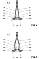
- the blades 5 are made up of several prefabricated, also reinforced with continuous fibers Parts put together, as shown in Figures 4 and 5 is shown schematically. On these figures received below.
- the blades 5 have as Base each on a base plate 8.
- the surface 9 the hub 2 facing side of the foot plate 8 is this Surface 9 adapted so precisely that this base plate 8 the surface 9 rests positively.
- the surface 9 has a on the inlet side of the compressor wheel 1 Paragraph 10 on which the entry end 11 the base plate 8 also lies positively.
- the blades 5 are in a known manner aerodynamically designed, the corresponding spherical In the drawing, the curvature of the airfoils is the For the sake of clarity, not shown.
- the blades 5 are based on the preformed, uniformly thick base plate 8.
- Base plate 8 is with a bead 26 provided in the interior of the blade 5 protrudes and which extends in the direction of the longitudinal axis of the Blade 5 extends, always downstream is less pronounced.
- the foot plate 8 has one Underside 27 on the surface 9 of the hub 2 is fully aligned.
- the in the bottom 27 as The result of the bulge 26 is by means of a depression Epoxy resin filling 28 so filled that in this Area of the base plate 8 one of the surface 9 of the hub 2 fully aligned surface is available.
- the bead 26 is provided with evenly rounded flanks.
- the The airfoil is separated by two side walls 29 and 30 educated.
- the side walls 29 and 30 are made of uniform thick plastic plates reinforced with continuous fibers manufactured, they close you closer in the radial direction becoming cavity 31. This cavity 31 can to a To achieve better vibration damping, foamed become.
- the cavity 31 is in the area of the leading edge 6 the blade 5 by means of a not shown, aerodynamically designed cover closed.
- the side walls 29 and 30 are preformed. You will be in a mounting template glued to the base plate 8 or with this welded. At the same time, the side walls 29 and 30 in the area of the tip of the blades 5 flat glued or welded together. Sidewalls 29 and 30 are designed so that they each have a foot part 32a, 32b have the form-fitting on the surface of the Base plate 8 fits, and the radius 33 merges into the approximately radial portion of each Side wall.
- the foot part 32a is the side wall 29 assigned and the foot portion 32b of the side wall 30.
- On the upstream side of the foot parts 32a and 32b each molded end pieces, which the end piece 11 of Adjusted footplate 8, form-fitting on the surface of the Rest footplate 8.
- the radius 33 is the radius of the Flank of the bead 26 exactly adjusted. As a result of the exact Adjustment of the foot parts 32a and 32b of the side walls 29 and 30 to the base plate 8 you get uniform adhesive joints, which enable a particularly durable bond.
- FIG. 5 shows a partial section through a second Embodiment of a rotor blade 5 of a compressor wheel 1.
- This embodiment differs from that Embodiment according to Figure 4 in that the approximately radial portion of the side walls 29 and 30 somewhat is bulged. This shape ensures that with mechanical stress on the blades 5 the Tensions between the foot parts 32a and 32b of the Side walls 29 and 30 and the base plate 8 clearly can be reduced, the blades 5 thus formed therefore particularly resistant to high centrifugal forces.
- a blade 5 designed in this way equipped compressor wheel 1 is for particularly high Circumferential speeds suitable.
- the hub 2 has a collar 12 on the outlet side, against which the outlet-side end 13 of the rotor blade 5 bumps.
- the end 13 is formed from the one with the foot parts 32a and 32b covered footplate 8.
- the collar 12 is on this point the same width as the thickness of this exit-side end 13 of the blade 5, so that none protruding edge the flow of the compressor wheel 1 outflowing compressed medium disturbs.
- the bottom of the Base plate 8 is glued to the surface 9 of the hub 2 or welded.
- the foot plates 8 are so with the Foot parts 32a and 32b covered that when finished Compressor wheel 1, the entire surface 9 is covered.
- an adhesive bandage 14 is additionally attached, that the end piece 11 of each foot plate 8 together with the End pieces of the foot parts 32a and 32b against the paragraph 10 of the Hub 2 is pressed.
- the bandage 14 is made from a prefabricated plastic tape reinforced with continuous fibers wrapped. In this case, plastic is suitable particularly temperature-resistant thermoplastics, which with Carbon fibers are reinforced.
- the bandage 14 was like this that wrapped the carbon fibers circumferentially lie, which is a particularly high strength of the bandage 14 in this direction has the consequence that the foot plates 8 and the foot parts 32a and 32b even with comparatively large ones Speeds of the compressor wheel 1 are kept safe.
- the thermoplastic material of the Band heated briefly and with the previously applied position of the tape fused.
- the bandage 14 is therefore manufactured using the same process as the hub 2. After winding, the surface 15 of the Bandage 14 reworked to a streamlined shape to reach the bandage 14.
- the blades 5 by gluing or welding, the Bandage 14 and the waistband 12 held. Up to comparative high speeds of the compressor wheel 1 is sufficient Fastening fully. However, even higher speeds required, the blades 5 are additionally means Metal rivets riveted to the hub 2, namely the Foot parts 32a and 32b together with the foot plates 8 with the Hub 2 riveted. When riveting, care is taken that the rivet heads the flow of the medium in the Do not disturb flow channels, as this will reduce efficiency would result.
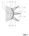
- FIG. 2 shows a schematically illustrated partial section by the compressor wheel according to Fig.1, and it shows the Section A-A.
- Blades 5 have in the edge area where they touch adjacent blades 5, bevels 16a, 16b on a sliding of the edges of the Blades 5 and an effective gluing thereof allow, whereby a closed surface 17 of the Axis 4 facing side of the flow channel 18 is reached becomes.
- the dashed line 19 indicates the compressor housing which the side through the blades 5 closes limited flow channel 18 to the outside.
- FIG. 3 shows a partial section through a second Embodiment of a compressor wheel.
- This embodiment differs from that according to FIG. 1 in that in the space between two blades 5 each one further blade 20 is provided, the one Has leading edge 21 which is downstream of the Leading edge 6 of the blades 5 is arranged.
- everyone Flow channel is downstream through the blade 20 divided into two flow channels.
- the blade 20 has a trailing edge that is in the same plane as the trailing edge 7 of the blades 5 is arranged.
- the Rotor blades 20 correspond to the rotor blades 5 educated.
- the blades 20 are also with a Provide footplate on which the corresponding foot parts have been applied.
- This footplate and the one with it connected foot parts fit exactly in recesses of the Foot parts 32a and 32b of the blades 5, the Blades 20 each form-fitting under the Blades 5 are pushed. Hold the blades 5 the blades 20 in addition to their gluing or Welding by means of a dovetail Gearing.
- the blades 20 are accordingly similar the hub 2 fastened like the blades 5.
- the foot parts 32a and 32b of the blades 5 have in this embodiment as well as the foot parts of the blades 20 on the molded end pieces on the downstream side on which the outlet-side end piece 22 of the footplate 8 adapted, form-fitting on the surface of the footplate 8 rest.
- the end piece 22 is positively on one Paragraph 23 of the hub 2.
- Embodiment of the compressor wheel 1 is after gluing or welding the blades 5 and 20 and after Hardening the adhesive a bandage 24 in addition to Bandage 14 attached so that the end pieces 22 of each of the Blades 5 and each of the blades 20 together with the end pieces of the respective foot parts against paragraph 23 the hub 2 are pressed.
- the bandage 24 is the same as the bandage 14, made of a prefabricated, with continuous fibers reinforced plastic tape wrapped and accordingly welded.
- the surface of the bandage 24 is then also aerodynamically designed.
- the compressor wheel 1 according to FIG. 3 also has one Balancing ring 25, which when winding into the hub 2 was admitted.
- the balancing ring 25 is made of metal manufactured. When balancing the finished compressor wheel 1 25 material is removed from this balancing ring eliminate existing imbalances. It is also possible that Execute sleeve 3 with a larger mass and the necessary material removal on this, so that the Balancing ring 25 can be saved.
- an adhesive based on a Phenolic resin here is the adhesive HT 424 American Cyanamid Company, 1300 Revolution Street, Havre de Grace, MD 21087, proved to be particularly suitable. Furthermore, the adhesive is also based on a modified condensation polyimides of the same Manufacturer called FM 36 good for this described assembling suitable. Except for gluing for connecting the parts of the blades 5 also a Welding process using a laser or a combination both methods conceivable. The blades 20 are put together in the same way.
- the tape for the manufacture of the hub 2 and the bandages 14 and 24 has a matrix of a thermoplastic.
- Thermoplastic has in particular polyphenylene sulfide proven, also good with polyether ether ketone Results achieved.
- the matrix was made of polyphenylene sulfide with a volume content of carbon fibers of about 53% reinforced.
- the cross section of this tape was 5mm x 0.158mm.
- the elastic modulus of the tape was 114 GPa.
- the operating temperature in this case was approximately 220 ° C.
- the matrix of polyether ether ketone was covered with a Volume content of carbon fibers increased by 61%.
- the Cross section of this tape was 5mm x 0.125mm.
- the elastic modulus of the tape was 134,000 MPa. The In this case, the operating temperature was around 280 ° C.
- the blades 5, 20 become a thermoplastic used with the trained as continuous fibers Carbon fiber is reinforced. This material is in shape delivered from uniformly thick panels. As special a matrix made of polyether ether ketone has been suitable a volume content of carbon fibers of 61%. This Plates are placed in molds and under thermal Application using one of the known methods in the final shape, taking care that the continuous filaments in the direction of the dynamic Main stress of the blades 5,20 are aligned. The prefabricated components, the side walls 29 and 30 and the base plate 8, the blades 5, 20 are then as already described, to manufacture in an assembly template Blade 5 or 20 assembled.
Landscapes
- Engineering & Computer Science (AREA)
- Mechanical Engineering (AREA)
- General Engineering & Computer Science (AREA)
- Structures Of Non-Positive Displacement Pumps (AREA)
Claims (10)
- Compresseur avec une roue de compresseur (1) présentant un moyeu (2) en matière plastique garni d'aubes mobiles (5), avec un arbre qui s'étend le long d'un axe (4) et assemblé au moyeu (2), avec un corps entourant la roue de compresseur (1), caractérisé en ce quele moyeu (2) est fabriqué en un thermoplastique renforcé avec des fibres de longueur illimitée, et en ce queles aubes mobiles (5, 20) sont préfabriquées séparément en un thermbplastique renforcé avec des fibres de longueur illimitée et sont assemblées géométriquement au moyeu (2).
- Compresseur suivant la revendication 1, caractérisé en ce quele moyeu (2) est bobiné en couches sur un gabarit correspondant, la matière thermoplastique ayant été chauffée brièvement pendant le bobinage et chaque fois fusionnée avec la couche respective déposée précédemment.
- Compresseur suivant la revendication 2, caractérisé en ce quele moyeu (2) est bobiné à partir d'une bande thermoplastique préfabriquée, renforcée par des fibres de carbone.
- Compresseur suivant la revendication 3, caractérisé en ce quela matrice de la bande thermoplastique est formée à partir de sulfure de polyphénylène.
- Compresseur suivant la revendication 3, caractérisé en ce quela matrice de la bande thermoplastique est formée à partir de polyétheréther-cétone.
- Compresseur suivant la revendication 1, caractérisé en ce queles aubes mobiles (5, 20) sont assemblées à partir d'au moins deux pièces détachées préfabriquées.
- Compresseur suivant la revendication 1, caractérisé en ce queles pièces détachées des aubes mobiles (5, 20) sont assemblées au moyen d'une opération de collage ou de soudage, et en ce quela fixation géométrique des aubes mobiles (5, 20) est effectuée au moyen d'une opération de collage ou de soudage.
- Compresseur suivant la revendication 7, caractérisé en ce quela fixation des aubes mobiles (5, 20) est renforcée au moyen d'au moins un bandage (14, 24) en une bande thermoplastique préfabriquée, renforcée par des fibres de carbone, la matière thermoplastique ayant été chauffée brièvement pendant le bobinage du bandage (14, 24) et fusionnée avec la couche respective déposée précédemment.
- Compresseur suivant la revendication 1, caractérisé en ce quele moyeu (2) est fretté sur un manchon (3) en métal qui est conçu pour recevoir l'arbre.
- Compresseur suivant la revendication 1, caractérisé en ce quel'on utilise des rivets pour la fixation géométrique des aubes mobiles (5, 20).
Applications Claiming Priority (2)
| Application Number | Priority Date | Filing Date | Title |
|---|---|---|---|
| DE19513508 | 1995-04-10 | ||
| DE19513508A DE19513508A1 (de) | 1995-04-10 | 1995-04-10 | Verdichter |
Publications (2)
| Publication Number | Publication Date |
|---|---|
| EP0737814A1 EP0737814A1 (fr) | 1996-10-16 |
| EP0737814B1 true EP0737814B1 (fr) | 2000-03-01 |
Family
ID=7759344
Family Applications (1)
| Application Number | Title | Priority Date | Filing Date |
|---|---|---|---|
| EP96810177A Expired - Lifetime EP0737814B1 (fr) | 1995-04-10 | 1996-03-20 | Compresseur |
Country Status (8)
| Country | Link |
|---|---|
| US (1) | US5632601A (fr) |
| EP (1) | EP0737814B1 (fr) |
| JP (1) | JPH08296590A (fr) |
| KR (1) | KR960038140A (fr) |
| CN (1) | CN1136142A (fr) |
| CZ (1) | CZ95896A3 (fr) |
| DE (2) | DE19513508A1 (fr) |
| PL (1) | PL313679A1 (fr) |
Families Citing this family (31)
| Publication number | Priority date | Publication date | Assignee | Title |
|---|---|---|---|---|
| DE19632893C2 (de) * | 1996-08-16 | 2001-02-08 | Industrieanlagen Betr Sgmbh Ia | Verfahren zur Herstellung von Flugkörperkomponenten aus faserverstärkter Keramik |
| FI101565B (fi) * | 1997-01-17 | 1998-07-15 | Flaekt Woods Ab | Haihdutinpuhallin ja sen siipipyörä |
| FI101564B (fi) * | 1997-01-17 | 1998-07-15 | Flaekt Woods Ab | Korkeapainepuhallin |
| DE19723845A1 (de) * | 1997-06-06 | 1998-12-10 | Abb Research Ltd | Verfahren zur Herstellung von Schaufeln aus polymerem Verbundmaterial |
| FR2776030B1 (fr) * | 1998-03-11 | 2000-07-13 | Abb Solyvent Ventec | Roue de ventilation centrifuge en materiaux composites |
| US6224339B1 (en) | 1998-07-08 | 2001-05-01 | Allison Advanced Development Company | High temperature airfoil |
| DE19912715A1 (de) * | 1999-03-20 | 2000-09-21 | Abb Research Ltd | Verdichterrad |
| DE10234093A1 (de) * | 2002-07-26 | 2004-02-05 | Robert Bosch Gmbh | Vorrichtung zur Verdichtung von Verbrennungsluft |
| DE10253299B4 (de) * | 2002-11-15 | 2004-09-30 | Daimlerchrysler Ag | Laufrad |
| EP1633985A1 (fr) * | 2003-01-17 | 2006-03-15 | Robert Bosch Gmbh | Turbine d'une turbomachine |
| EP1627726A1 (fr) * | 2004-08-18 | 2006-02-22 | ABB Turbo Systems AG | Compresseur renforcé par des fibres |
| EP2302172A1 (fr) | 2004-11-12 | 2011-03-30 | Board of Trustees of Michigan State University | Machine comprenant un rotor tissé électromagnétique et procédé de fabrication |
| US8142160B2 (en) * | 2006-10-24 | 2012-03-27 | Lg Electronics Inc. | High speed type impeller having a reinforcing ring |
| US8182213B2 (en) * | 2009-04-22 | 2012-05-22 | Pratt & Whitney Canada Corp. | Vane assembly with removable vanes |
| IT1394295B1 (it) | 2009-05-08 | 2012-06-06 | Nuovo Pignone Spa | Girante centrifuga del tipo chiuso per turbomacchine, componente per tale girante, turbomacchina provvista di tale girante e metodo di realizzazione di tale girante |
| IT1397057B1 (it) | 2009-11-23 | 2012-12-28 | Nuovo Pignone Spa | Girante centrifuga e turbomacchina |
| IT1397058B1 (it) | 2009-11-23 | 2012-12-28 | Nuovo Pignone Spa | Stampo per girante centrifuga, inserti per stampo e metodo per costruire una girante centrifuga |
| US8794914B2 (en) | 2010-11-23 | 2014-08-05 | GM Global Technology Operations LLC | Composite centrifugal compressor wheel |
| ITCO20110064A1 (it) | 2011-12-14 | 2013-06-15 | Nuovo Pignone Spa | Macchina rotante comprendente un rotore con una girante composita ed un albero metallico |
| DE202011052411U1 (de) * | 2011-12-21 | 2013-03-22 | Ebm-Papst Mulfingen Gmbh & Co. Kg | Schaufelrad für Axialventilatoren oder Radial- und Diagonallüfter |
| US9777579B2 (en) | 2012-12-10 | 2017-10-03 | General Electric Company | Attachment of composite article |
| US9797257B2 (en) | 2012-12-10 | 2017-10-24 | General Electric Company | Attachment of composite article |
| RU2522152C1 (ru) * | 2013-03-21 | 2014-07-10 | Открытое акционерное общество Научно-производственное объединение "Искра" | Ротор центробежного компрессора |
| JP6131085B2 (ja) * | 2013-04-01 | 2017-05-17 | 株式会社神戸製鋼所 | 回転機械、回転機械に用いられる羽根車、及び、羽根車の製造方法 |
| US20140322019A1 (en) * | 2013-04-30 | 2014-10-30 | Dresser Inc. | Rotary element and compressor device comprised thereof |
| ITCO20130067A1 (it) | 2013-12-17 | 2015-06-18 | Nuovo Pignone Srl | Girante con elementi di protezione e compressore centrifugo |
| CA2945652C (fr) | 2014-05-05 | 2020-11-03 | Horton, Inc. | Ventilateur composite |
| JP6309884B2 (ja) * | 2014-11-25 | 2018-04-11 | 三菱重工業株式会社 | インペラ、及び回転機械 |
| JP6210459B2 (ja) * | 2014-11-25 | 2017-10-11 | 三菱重工業株式会社 | インペラ、及び回転機械 |
| DE102016108762A1 (de) * | 2016-05-12 | 2017-11-16 | Man Diesel & Turbo Se | Radialverdichter |
| US10393134B2 (en) * | 2017-08-04 | 2019-08-27 | Borgwarner Inc. | Polymeric compressor wheel with metal sleeve |
Family Cites Families (20)
| Publication number | Priority date | Publication date | Assignee | Title |
|---|---|---|---|---|
| US1535417A (en) * | 1924-07-05 | 1925-04-28 | Ingersoll Rand Co | Open impeller |
| US2848190A (en) * | 1952-10-02 | 1958-08-19 | Power Jets Res & Dev Ltd | Radial flow turbo-machines |
| US3070844A (en) * | 1952-12-15 | 1963-01-01 | Studebaker Packard Corp | Machine for making stator blades and the like |
| US2848192A (en) * | 1953-03-12 | 1958-08-19 | Gen Motors Corp | Multi-piece hollow turbine bucket |
| US3521973A (en) * | 1968-08-16 | 1970-07-28 | Anpol Research Corp | Fan construction |
| GB1279016A (en) * | 1969-05-30 | 1972-06-21 | Normalair Garrett Ltd | Improvements in or relating to methods of manufacture of bladed or toothed components |
| GB1341578A (en) * | 1972-08-20 | 1973-12-25 | British Leyland Truck & Bus | Rotary compressors |
| DE2618829C3 (de) * | 1976-04-29 | 1983-03-03 | Klein, Schanzlin & Becker Ag, 6710 Frankenthal | Lagerung einer mehrstufigen Kreiselpumpe |
| US4260327A (en) * | 1979-07-25 | 1981-04-07 | General Electric Company | Guide vane assembly for reverse flow cooled dynamoelectric machine |
| FR2539824A1 (fr) * | 1983-01-26 | 1984-07-27 | Applic Rationnelles Physiq | Roue pour compresseur centrifuge et procede pour sa fabrication |
| DE3307386A1 (de) * | 1983-03-02 | 1984-09-06 | Wilden Kg, 8473 Pfreimd | Laufrad fuer pumpen, verdichter, geblaese und dgl. |
| GB2161110B (en) * | 1984-07-07 | 1988-03-23 | Rolls Royce | An annular bladed member having an integral shroud and a method of manufacture thereof |
| FR2631083B1 (fr) * | 1988-05-03 | 1993-06-04 | Plastiremo | Roue composite pour compresseur centrifuge et procede pour sa fabrication |
| CH675279A5 (fr) * | 1988-06-29 | 1990-09-14 | Asea Brown Boveri | |
| US5145320A (en) * | 1990-08-28 | 1992-09-08 | The United States Of America As Represented By The Secretary Of The Navy | Mass loaded composite rotor for vibro-acoustic application |
| DE4139293A1 (de) * | 1991-11-29 | 1993-06-03 | Inst Verbundwerkstoffe Gmbh | Faserkunststoffverbund-laufrad fuer eine radialstroemungsmaschine |
| EP0593797B1 (fr) * | 1992-10-17 | 1996-07-10 | Asea Brown Boveri Ag | Dispositif de stabilisation pour l'extension de la tolérance de pompage d'un compresseur |
| FR2703111B1 (fr) * | 1993-03-25 | 1995-06-30 | Ozen Sa | Rotor pour pompe comportant deux pieces assemblees par soudure, obtenues par moulage par injection de materiaux thermoplastiques, et procede de fabrication d'un tel rotor . |
| DE4321173C2 (de) * | 1993-06-25 | 1996-02-22 | Inst Luft Kaeltetech Gem Gmbh | Radiallaufrad |
| US5431536A (en) * | 1994-02-01 | 1995-07-11 | General Motors Corporation | Molded torque converter stator and integral race for a one-way torque transmitter |
-
1995
- 1995-04-10 DE DE19513508A patent/DE19513508A1/de not_active Withdrawn
-
1996
- 1996-03-14 US US08/615,884 patent/US5632601A/en not_active Expired - Fee Related
- 1996-03-20 DE DE59604509T patent/DE59604509D1/de not_active Expired - Fee Related
- 1996-03-20 EP EP96810177A patent/EP0737814B1/fr not_active Expired - Lifetime
- 1996-03-27 KR KR1019960008653A patent/KR960038140A/ko not_active Withdrawn
- 1996-04-02 CZ CZ96958A patent/CZ95896A3/cs unknown
- 1996-04-09 PL PL96313679A patent/PL313679A1/xx unknown
- 1996-04-10 CN CN96107300A patent/CN1136142A/zh active Pending
- 1996-04-10 JP JP8088604A patent/JPH08296590A/ja active Pending
Also Published As
| Publication number | Publication date |
|---|---|
| CN1136142A (zh) | 1996-11-20 |
| KR960038140A (ko) | 1996-11-21 |
| US5632601A (en) | 1997-05-27 |
| JPH08296590A (ja) | 1996-11-12 |
| PL313679A1 (en) | 1996-10-14 |
| EP0737814A1 (fr) | 1996-10-16 |
| CZ95896A3 (en) | 1996-10-16 |
| DE59604509D1 (de) | 2000-04-06 |
| DE19513508A1 (de) | 1996-10-17 |
Similar Documents
| Publication | Publication Date | Title |
|---|---|---|
| EP0737814B1 (fr) | Compresseur | |
| EP0754863B1 (fr) | Soufflante | |
| EP1914383B1 (fr) | Aube de soufflante en matériau composite | |
| EP0207457B1 (fr) | Roue de pompe à eau | |
| DE3879287T2 (de) | Fvk-blatt und sein herstellungsverfahren. | |
| US3487879A (en) | Blades,suitable for propellers,compressors,fans and the like | |
| EP0596386B1 (fr) | Aube statorique ajustable fabriqué à partir de plastique renforcé par des fibres | |
| DE19903550C1 (de) | Blattwurzel für Propeller- und Rotorblätter | |
| DE102011078951B4 (de) | Verfahren zum Herstellen eines Rotorblatts für eine Windenergieanlage, Sandwich-Preform und Rotorblatt für eine Windenergieanlage | |
| EP1832733B1 (fr) | Cône d'entrée en matériau composite renforcé en fibres pour une turbine à gaz et son procédé de fabrication | |
| EP3054179A1 (fr) | Arbre d'une turbine a gaz fabrique en materiau composite | |
| EP3199451A1 (fr) | Nez de rotor d'un ventilateur de moteur à propulsion | |
| EP2212561B1 (fr) | Carter pour un compresseur radial | |
| DE1905971A1 (de) | Schaufel fuer Gasturbinen und Verfahren zur Herstellung einer solchen | |
| EP3106673B1 (fr) | Ventilateur comprenant au moins une roue de ventilateur et/ou d'autres parties de ventilateur et procédé de fabrication d'une partie de ventilateur | |
| DE102009004813B4 (de) | Faserverstärkte Kunststoffplatte mit laminiertem Buchseneinsatz | |
| EP3724511B1 (fr) | Roue de ventilateur diagonal a resistance amelioree | |
| DE3016862C2 (de) | Felgenrad | |
| DE3620097A1 (de) | Rad fuer kraftfahrzeuge | |
| EP0085127B1 (fr) | Rotor, en particulier pour aéronef à aile tournante, avec moyeu en matière plastique renforcé par des fibres | |
| DE4418051C2 (de) | Verdichterrad | |
| EP1627726A1 (fr) | Compresseur renforcé par des fibres | |
| WO2010097277A2 (fr) | Procédé pour monter ou confectionner un anneau de renfort fermé pour un aubage mobile d'un étage de turbine et aubage mobile d'un étage de turbine pour une turbine | |
| EP3015702B1 (fr) | Pale de rotor pour une eolienne et procede de fabrication d'une pale de rotor | |
| DE19907910A1 (de) | Lüfterrad |
Legal Events
| Date | Code | Title | Description |
|---|---|---|---|
| PUAI | Public reference made under article 153(3) epc to a published international application that has entered the european phase |
Free format text: ORIGINAL CODE: 0009012 |
|
| AK | Designated contracting states |
Kind code of ref document: A1 Designated state(s): DE FR GB |
|
| 17P | Request for examination filed |
Effective date: 19970310 |
|
| GRAG | Despatch of communication of intention to grant |
Free format text: ORIGINAL CODE: EPIDOS AGRA |
|
| GRAG | Despatch of communication of intention to grant |
Free format text: ORIGINAL CODE: EPIDOS AGRA |
|
| GRAH | Despatch of communication of intention to grant a patent |
Free format text: ORIGINAL CODE: EPIDOS IGRA |
|
| 17Q | First examination report despatched |
Effective date: 19990719 |
|
| GRAH | Despatch of communication of intention to grant a patent |
Free format text: ORIGINAL CODE: EPIDOS IGRA |
|
| GRAA | (expected) grant |
Free format text: ORIGINAL CODE: 0009210 |
|
| AK | Designated contracting states |
Kind code of ref document: B1 Designated state(s): DE FR GB |
|
| PG25 | Lapsed in a contracting state [announced via postgrant information from national office to epo] |
Ref country code: GB Free format text: LAPSE BECAUSE OF FAILURE TO SUBMIT A TRANSLATION OF THE DESCRIPTION OR TO PAY THE FEE WITHIN THE PRESCRIBED TIME-LIMIT Effective date: 20000301 Ref country code: FR Free format text: LAPSE BECAUSE OF FAILURE TO SUBMIT A TRANSLATION OF THE DESCRIPTION OR TO PAY THE FEE WITHIN THE PRESCRIBED TIME-LIMIT Effective date: 20000301 |
|
| REF | Corresponds to: |
Ref document number: 59604509 Country of ref document: DE Date of ref document: 20000406 |
|
| EN | Fr: translation not filed | ||
| GBV | Gb: ep patent (uk) treated as always having been void in accordance with gb section 77(7)/1977 [no translation filed] |
Effective date: 20000301 |
|
| PLBE | No opposition filed within time limit |
Free format text: ORIGINAL CODE: 0009261 |
|
| STAA | Information on the status of an ep patent application or granted ep patent |
Free format text: STATUS: NO OPPOSITION FILED WITHIN TIME LIMIT |
|
| PG25 | Lapsed in a contracting state [announced via postgrant information from national office to epo] |
Ref country code: DE Free format text: LAPSE BECAUSE OF NON-PAYMENT OF DUE FEES Effective date: 20010103 |
|
| 26N | No opposition filed |