EP0737610A2 - Direction à crémaillère hydraulique - Google Patents
Direction à crémaillère hydraulique Download PDFInfo
- Publication number
- EP0737610A2 EP0737610A2 EP96104750A EP96104750A EP0737610A2 EP 0737610 A2 EP0737610 A2 EP 0737610A2 EP 96104750 A EP96104750 A EP 96104750A EP 96104750 A EP96104750 A EP 96104750A EP 0737610 A2 EP0737610 A2 EP 0737610A2
- Authority
- EP
- European Patent Office
- Prior art keywords
- rack
- bore
- pinion steering
- piston
- pressure connection
- Prior art date
- Legal status (The legal status is an assumption and is not a legal conclusion. Google has not performed a legal analysis and makes no representation as to the accuracy of the status listed.)
- Granted
Links
Images
Classifications
-
- B—PERFORMING OPERATIONS; TRANSPORTING
- B62—LAND VEHICLES FOR TRAVELLING OTHERWISE THAN ON RAILS
- B62D—MOTOR VEHICLES; TRAILERS
- B62D5/00—Power-assisted or power-driven steering
- B62D5/06—Power-assisted or power-driven steering fluid, i.e. using a pressurised fluid for most or all the force required for steering a vehicle
- B62D5/10—Power-assisted or power-driven steering fluid, i.e. using a pressurised fluid for most or all the force required for steering a vehicle characterised by type of power unit
- B62D5/12—Piston and cylinder
-
- B—PERFORMING OPERATIONS; TRANSPORTING
- B62—LAND VEHICLES FOR TRAVELLING OTHERWISE THAN ON RAILS
- B62D—MOTOR VEHICLES; TRAILERS
- B62D5/00—Power-assisted or power-driven steering
- B62D5/06—Power-assisted or power-driven steering fluid, i.e. using a pressurised fluid for most or all the force required for steering a vehicle
- B62D5/061—Power-assisted or power-driven steering fluid, i.e. using a pressurised fluid for most or all the force required for steering a vehicle provided with effort, steering lock, or end-of-stroke limiters
-
- B—PERFORMING OPERATIONS; TRANSPORTING
- B62—LAND VEHICLES FOR TRAVELLING OTHERWISE THAN ON RAILS
- B62D—MOTOR VEHICLES; TRAILERS
- B62D5/00—Power-assisted or power-driven steering
- B62D5/06—Power-assisted or power-driven steering fluid, i.e. using a pressurised fluid for most or all the force required for steering a vehicle
- B62D5/08—Power-assisted or power-driven steering fluid, i.e. using a pressurised fluid for most or all the force required for steering a vehicle characterised by type of steering valve used
-
- B—PERFORMING OPERATIONS; TRANSPORTING
- B62—LAND VEHICLES FOR TRAVELLING OTHERWISE THAN ON RAILS
- B62D—MOTOR VEHICLES; TRAILERS
- B62D5/00—Power-assisted or power-driven steering
- B62D5/06—Power-assisted or power-driven steering fluid, i.e. using a pressurised fluid for most or all the force required for steering a vehicle
- B62D5/20—Power-assisted or power-driven steering fluid, i.e. using a pressurised fluid for most or all the force required for steering a vehicle specially adapted for particular type of steering gear or particular application
- B62D5/22—Power-assisted or power-driven steering fluid, i.e. using a pressurised fluid for most or all the force required for steering a vehicle specially adapted for particular type of steering gear or particular application for rack-and-pinion type
Definitions
- the invention relates to a hydraulic rack and pinion steering, in which a working piston is guided into a hydraulic cylinder which has an end stop limitation, by means of which, in an end position of the working piston, a path from the pressurized working space to a lower pressure space is formed for the pressure medium supplied to the working piston via pressure medium bores .
- the working piston is moved in one direction by the pressurization until a mechanical stop is reached somewhere, for example a stop formed in the area of a tie rod axial joint and the steering housing.
- the steering must therefore be designed overall for a higher load, which has a high weight and corresponding production costs.
- the present invention has for its object to improve a rack and pinion steering of the generic type in such a way that it is easy to manufacture with little economic effort.
- a generic rack and pinion steering system is further developed by at least one hole in the area of each pressure connection hole that can be executed and closed from the outside of the housing and can be connected to the respective pressure connection via a connecting line.
- the rack and pinion steering system comprises a bore which is essentially parallel to the respective pressure connection bore and which is offset in the direction of the respective other pressure connection.
- These two mutually opposite bores ie a total of four bores over the cylinder of the rack and pinion steering, are essentially parallel to one another.
- the two bores located on the outside, ie at the end of the cylinder, serve to connect the pressure supply lines.
- the two internal bores can be connected to the pressure connections using appropriate connecting lines. If the piston overflows the respective inner bore, both pressure connections are thus connected to one another, so that a hydraulic limit stop limitation is provided.
- the Distance between the inner bores and the pressure connection bores to each other is larger than the working piston is wide. The end stop is then in front of the respective pressure connection bore, which simplifies movement of the piston in the opposite direction.
- the connecting line is designed to run essentially in the direction of piston movement.
- this connecting line is also a hole made from the outside of the housing.
- the housing has a hood-like extension in the pressure connection area.
- This hood-like extension serves to form the desired holes and can be produced with simple means.
- This hood-like extension can also be retrofitted after forming a vertical bore and have a horizontal line.
- the outer seal area can be formed by conventional means, welding, gluing or the like. This measure makes the production of the necessary lines particularly easy.
- a check valve is arranged in at least one of the bores.
- the arrangement of the check valve makes it easy to implement the different directions of movement of the piston hydraulically.
- the invention proposes a rack and pinion steering system which can be produced with simple means and is economically simple and which has a hydraulic limit stop limitation without having the disadvantages known from the prior art.
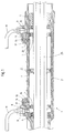
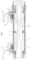
- FIGS. 1 and 2 the area of the cylinder 2 is shown in which a piston 3, which is arranged on a rack shaft 25, can be moved back and forth.
- the piston positions 4 and 5 in the respective end stop areas are shown in dashed lines in FIG. 1.
- the cylinder is closed at both ends by a seal 6, 7.
- the rack shaft 25 is designed in one direction in a manner not shown as a rack and is connected to the pinion of a power steering valve. At both outer ends of the rack shaft, it is connected in a manner not shown to joints of a steering system, not shown.
- a pressure connection 8, 9 is formed at both ends of the cylinder 2, which is formed in a housing. In the exemplary embodiments shown, this is accommodated in an extension 26 which is hood-shaped.
- the pressure lines 18, 19 are inserted into the threaded bores 8, 9 with conventional screw connections. Both sides of the piston can now be pressurized.
- a parallel bore 10, 11 is formed next to each pressure connection 8, 9 in each case to the center of the cylinder and is connected to the pressure connection 8, 9 by a connecting bore 12, 13. If the piston 3 is pressurized via the pressure line 19 and the pressure connection 9, which each lead into the right cylinder chamber, it moves in the image plane seen to the left.
- the pressure port 8 and thus the discharge pressure line 18 is connected to the right cylinder chamber via the parallel bore 10 and the connecting bore 12. This results in partial pressure equalization and the piston moves to the end stop position with reduced pressure.
- the piston By reversing the pressure guide, the piston can be pressurized on the left side and then moves into the right end stop position shown in FIG. 1.
- the parallel and connecting bores 10, 11, 12, 13 are shown tapered in the lower area, i. H. designed as so-called aperture bores 20.
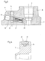
- a check valve 21 is inserted into the connecting bore 12 and the connecting bore 13. This detail is shown in FIG. 3 using the right pressure connection bore 9.
- the check valve opens in the event that the piston moves over the parallel bore 11 when moving into the right stop position shown in FIG. 1.
- the pressure supplied via the pressure line 18 is then returned to the pressure line 19 via the pressure connection 9. If the piston is pressurized on the right side, i. H. Via the pressure line 19 and the pressure connection 9, the check valve 1 closes and the piston approach is fully supported hydraulically, as in steering gears without limit stop device.
- the bores designed as an aperture bore 20, all of which are otherwise closed with closure means known per se, are run over on the inner wall of the cylinder by the piston with its outer seals.
- 4 shows an embodiment.
- this consists of an outer sealing ring 23 and a inner sealing ring 24 is formed, the inner sealing ring applying radial spring forces to bring the outer sealing ring 23 into a stop against the inner wall of the cylinder 2.
- the wide design of the sealing ring is particularly important, which prevents the seals from being damaged by driving over the orifice holes.
- the extension 26 shown in the exemplary embodiment shown is designed in one piece with the housing and rises like a hood or dome around the pressure connections 8 and 9.
- This extension can also be formed by additionally applied and sealingly connected shell elements, the threaded holes, longitudinal and Has cross holes and the like. In this case, bores can also be formed by milled grooves in the extension shell.
Applications Claiming Priority (2)
| Application Number | Priority Date | Filing Date | Title |
|---|---|---|---|
| DE19514244A DE19514244A1 (de) | 1995-04-15 | 1995-04-15 | Hydraulische Zahnstangenlenkung |
| DE19514244 | 1995-04-15 |
Publications (3)
| Publication Number | Publication Date |
|---|---|
| EP0737610A2 true EP0737610A2 (fr) | 1996-10-16 |
| EP0737610A3 EP0737610A3 (fr) | 1997-02-12 |
| EP0737610B1 EP0737610B1 (fr) | 2000-05-24 |
Family
ID=7759782
Family Applications (1)
| Application Number | Title | Priority Date | Filing Date |
|---|---|---|---|
| EP96104750A Expired - Lifetime EP0737610B1 (fr) | 1995-04-15 | 1996-03-26 | Direction à crémaillère hydraulique |
Country Status (8)
| Country | Link |
|---|---|
| US (1) | US5868216A (fr) |
| EP (1) | EP0737610B1 (fr) |
| JP (1) | JPH0986428A (fr) |
| KR (1) | KR960037476A (fr) |
| BR (1) | BR9601371A (fr) |
| CZ (1) | CZ103096A3 (fr) |
| DE (2) | DE19514244A1 (fr) |
| ES (1) | ES2146805T3 (fr) |
Cited By (4)
| Publication number | Priority date | Publication date | Assignee | Title |
|---|---|---|---|---|
| WO2000027686A1 (fr) * | 1998-11-11 | 2000-05-18 | Mercedes Benz Lenkungen Gmbh | Ensemble soupape pour direction assistee |
| WO2001056862A1 (fr) * | 2000-02-05 | 2001-08-09 | Zf Lenksysteme Gmbh | Servomoteur comportant un piston de travail, en particulier pour directions actionnees par une force exterieure ou auxiliaire de vehicules automobiles |
| WO2007045397A1 (fr) * | 2005-10-19 | 2007-04-26 | Eaton Fluid Power Gmbh | Servocommande pour direction assistee |
| DE102008027734A1 (de) | 2008-06-11 | 2009-12-17 | Trw Automotive Gmbh | Zylinder/Kolben-Einheit |
Families Citing this family (8)
| Publication number | Priority date | Publication date | Assignee | Title |
|---|---|---|---|---|
| DE19725944C1 (de) * | 1997-06-19 | 1998-12-24 | Trw Fahrwerksyst Gmbh & Co | Hydraulische Zahnstangenlenkung |
| KR20040015500A (ko) * | 2002-08-13 | 2004-02-19 | 현대모비스 주식회사 | 파워스티어링 기어박스의 랙바 충격 방지장치 |
| FR2857324B1 (fr) * | 2003-07-08 | 2006-09-15 | Koyo Steering Europe Kse | Palier pour direction assistee hydraulique de vehicule automobile |
| DE102006004724A1 (de) * | 2006-02-02 | 2007-08-09 | Bayerische Motoren Werke Ag | Hydraulikzylinder mit einem Kolben insbesondere für eine hydraulische Servolenkung |
| KR101407822B1 (ko) * | 2013-07-01 | 2014-06-18 | 구광모 | 소독약 살포기의 바퀴 조향용 유압실린더 |
| DE102014117327A1 (de) * | 2014-11-26 | 2016-06-02 | Robert Bosch Automotive Steering Gmbh | Lenksystem für ein Kraftfahrzeug und Verfahren zum Entlüften eines Lenksystems für ein Kraftfahrzeug |
| WO2018222845A1 (fr) * | 2017-05-31 | 2018-12-06 | R.H. Sheppard Co., Inc. | Ensemble piston destiné à un mécanisme de direction assistée |
| US20220355854A1 (en) * | 2021-05-04 | 2022-11-10 | Ronald Gene Timmons | Self-centering double ended hydraulic steering cylinder that uses no electronics |
Citations (3)
| Publication number | Priority date | Publication date | Assignee | Title |
|---|---|---|---|---|
| GB1444631A (en) * | 1973-09-04 | 1976-08-04 | Adwest Eng Ltd | Double-acting piston and cylinder means |
| DE1967046A1 (de) * | 1968-05-21 | 1976-09-23 | Southwire Co | Verfahren zur herstellung eines aluminiumlegierungsdrahtes mit einer elektrischen leitfaehigkeit von wenigstens 61 prozent iacs |
| US4828068A (en) * | 1984-02-02 | 1989-05-09 | General Motors Corporation | Hydraulically power assisted steering gear with pressure relief stop |
Family Cites Families (6)
| Publication number | Priority date | Publication date | Assignee | Title |
|---|---|---|---|---|
| US2867129A (en) * | 1953-10-28 | 1959-01-06 | Gen Motors Corp | Fluid power steering valve |
| US3437166A (en) * | 1967-05-17 | 1969-04-08 | Jeffrey Galion Inc | Steering system for vehicles |
| DE1967046U (de) * | 1967-05-29 | 1967-08-24 | Vakutronik Wissenschaftlicher | Pneumatikantrieb mit daempfung in den endlagen. |
| DE3721826C1 (de) * | 1987-07-02 | 1988-11-17 | Daimler Benz Ag | Servoventilanordnung |
| DE3929572A1 (de) * | 1988-09-10 | 1990-03-15 | Zahnradfabrik Friedrichshafen | Hilfskraftlenkung, insbesondere fuer kraftfahrzeuge |
| DE4221459A1 (de) * | 1992-06-30 | 1994-01-05 | Teves Gmbh Alfred | Hydraulische Servolenkung mit Belastungsschutzeinrichtung |
-
1995
- 1995-04-15 DE DE19514244A patent/DE19514244A1/de not_active Withdrawn
-
1996
- 1996-03-26 DE DE59605280T patent/DE59605280D1/de not_active Expired - Fee Related
- 1996-03-26 ES ES96104750T patent/ES2146805T3/es not_active Expired - Lifetime
- 1996-03-26 EP EP96104750A patent/EP0737610B1/fr not_active Expired - Lifetime
- 1996-04-09 CZ CZ961030A patent/CZ103096A3/cs unknown
- 1996-04-12 US US08/631,531 patent/US5868216A/en not_active Expired - Fee Related
- 1996-04-12 KR KR1019960010932A patent/KR960037476A/ko not_active Application Discontinuation
- 1996-04-12 JP JP8091394A patent/JPH0986428A/ja active Pending
- 1996-04-15 BR BR9601371A patent/BR9601371A/pt not_active IP Right Cessation
Patent Citations (3)
| Publication number | Priority date | Publication date | Assignee | Title |
|---|---|---|---|---|
| DE1967046A1 (de) * | 1968-05-21 | 1976-09-23 | Southwire Co | Verfahren zur herstellung eines aluminiumlegierungsdrahtes mit einer elektrischen leitfaehigkeit von wenigstens 61 prozent iacs |
| GB1444631A (en) * | 1973-09-04 | 1976-08-04 | Adwest Eng Ltd | Double-acting piston and cylinder means |
| US4828068A (en) * | 1984-02-02 | 1989-05-09 | General Motors Corporation | Hydraulically power assisted steering gear with pressure relief stop |
Cited By (5)
| Publication number | Priority date | Publication date | Assignee | Title |
|---|---|---|---|---|
| WO2000027686A1 (fr) * | 1998-11-11 | 2000-05-18 | Mercedes Benz Lenkungen Gmbh | Ensemble soupape pour direction assistee |
| US6345682B1 (en) | 1998-11-11 | 2002-02-12 | Mercedes Benz Lenkungen Gmbh | Valve arrangement for power-assisted steering systems |
| WO2001056862A1 (fr) * | 2000-02-05 | 2001-08-09 | Zf Lenksysteme Gmbh | Servomoteur comportant un piston de travail, en particulier pour directions actionnees par une force exterieure ou auxiliaire de vehicules automobiles |
| WO2007045397A1 (fr) * | 2005-10-19 | 2007-04-26 | Eaton Fluid Power Gmbh | Servocommande pour direction assistee |
| DE102008027734A1 (de) | 2008-06-11 | 2009-12-17 | Trw Automotive Gmbh | Zylinder/Kolben-Einheit |
Also Published As
| Publication number | Publication date |
|---|---|
| ES2146805T3 (es) | 2000-08-16 |
| EP0737610B1 (fr) | 2000-05-24 |
| JPH0986428A (ja) | 1997-03-31 |
| DE59605280D1 (de) | 2000-06-29 |
| DE19514244A1 (de) | 1996-10-17 |
| KR960037476A (ko) | 1996-11-19 |
| EP0737610A3 (fr) | 1997-02-12 |
| CZ103096A3 (en) | 1996-10-16 |
| BR9601371A (pt) | 1998-01-13 |
| US5868216A (en) | 1999-02-09 |
Similar Documents
| Publication | Publication Date | Title |
|---|---|---|
| DE1775565C3 (de) | In seiner Dämpfungscharakteristik verstellbarer Stoßdämpfer | |
| EP0756552B1 (fr) | Systeme de direction a essieux multiples pour vehicules | |
| DE3240105A1 (de) | Kolbenstangenloser zylinder | |
| DE1074346B (de) | Kolbenschieber | |
| EP0737610B1 (fr) | Direction à crémaillère hydraulique | |
| DE102005051324A1 (de) | Spülventil für einen hydraulischen Kreislauf | |
| DE3013381A1 (de) | Arbeitskolben-zylinder-einheit, insbesondere fuer zahnstangen-hilfskraftlenkungen von kraftfahrzeugen | |
| EP0764241B1 (fr) | Verin hydraulique | |
| EP0049406B1 (fr) | Disposition et perfectionnement pour les passages de fluide dans des cylindres | |
| EP0669469B1 (fr) | Actionneur fluidique rotatif | |
| DE4221459A1 (de) | Hydraulische Servolenkung mit Belastungsschutzeinrichtung | |
| DE3204112C2 (de) | Servo-Schieberventil | |
| DE2747842C2 (fr) | ||
| DE3024025C2 (de) | Hilfskraftlenkung für Fahrzeuge mit einem zwei Arbeitsräume aufweisenden Servozylinder | |
| DE2648608A1 (de) | Schaltvorrichtung fuer einen ein- oder mehrstufigen hydraulischen zylinder | |
| DE3135098A1 (de) | Ventilaufbau, umfassend ein pumpensteuer- bzw. -regelventil und eine entlastungsanordnung | |
| DE2725538C3 (de) | Hilfskraftunterstützte Zahnstangenlenkung für Kraftfahrzeuge | |
| DE1755697B2 (de) | Hydraulische Hilfskraftlenkeinrichtung für Kraftfahrzeuge | |
| EP1135614A1 (fr) | Clapet de non retour pilote destine a un systeme de portes pressions | |
| DE3104989A1 (de) | Servozylinder | |
| DE102008059437B3 (de) | Hydraulisches Steuerventil mit zwei Steuerkolben für einen einseitig arbeitenden Differentialzylinder | |
| DE3204303A1 (de) | Hydraulikzylinder | |
| DE19757157C2 (de) | Hydraulischer Linearantrieb | |
| DE2519973C3 (de) | Entlastungsventil | |
| EP0011145B1 (fr) | Patin pour machines à pistons hydrostatiques |
Legal Events
| Date | Code | Title | Description |
|---|---|---|---|
| PUAI | Public reference made under article 153(3) epc to a published international application that has entered the european phase |
Free format text: ORIGINAL CODE: 0009012 |
|
| AK | Designated contracting states |
Kind code of ref document: A2 Designated state(s): DE ES FR GB IT SE |
|
| PUAL | Search report despatched |
Free format text: ORIGINAL CODE: 0009013 |
|
| AK | Designated contracting states |
Kind code of ref document: A3 Designated state(s): DE ES FR GB IT SE |
|
| 17P | Request for examination filed |
Effective date: 19970226 |
|
| 17Q | First examination report despatched |
Effective date: 19981130 |
|
| GRAG | Despatch of communication of intention to grant |
Free format text: ORIGINAL CODE: EPIDOS AGRA |
|
| GRAG | Despatch of communication of intention to grant |
Free format text: ORIGINAL CODE: EPIDOS AGRA |
|
| GRAH | Despatch of communication of intention to grant a patent |
Free format text: ORIGINAL CODE: EPIDOS IGRA |
|
| GRAH | Despatch of communication of intention to grant a patent |
Free format text: ORIGINAL CODE: EPIDOS IGRA |
|
| GRAA | (expected) grant |
Free format text: ORIGINAL CODE: 0009210 |
|
| AK | Designated contracting states |
Kind code of ref document: B1 Designated state(s): DE ES FR GB IT SE |
|
| REF | Corresponds to: |
Ref document number: 59605280 Country of ref document: DE Date of ref document: 20000629 |
|
| GBT | Gb: translation of ep patent filed (gb section 77(6)(a)/1977) |
Effective date: 20000612 |
|
| ET | Fr: translation filed | ||
| ITF | It: translation for a ep patent filed |
Owner name: RACHELI & C. S.R.L. |
|
| REG | Reference to a national code |
Ref country code: ES Ref legal event code: FG2A Ref document number: 2146805 Country of ref document: ES Kind code of ref document: T3 |
|
| PGFP | Annual fee paid to national office [announced via postgrant information from national office to epo] |
Ref country code: GB Payment date: 20010202 Year of fee payment: 6 |
|
| PGFP | Annual fee paid to national office [announced via postgrant information from national office to epo] |
Ref country code: FR Payment date: 20010301 Year of fee payment: 6 |
|
| PGFP | Annual fee paid to national office [announced via postgrant information from national office to epo] |
Ref country code: ES Payment date: 20010315 Year of fee payment: 6 |
|
| PG25 | Lapsed in a contracting state [announced via postgrant information from national office to epo] |
Ref country code: SE Free format text: LAPSE BECAUSE OF NON-PAYMENT OF DUE FEES Effective date: 20010327 |
|
| PLBE | No opposition filed within time limit |
Free format text: ORIGINAL CODE: 0009261 |
|
| STAA | Information on the status of an ep patent application or granted ep patent |
Free format text: STATUS: NO OPPOSITION FILED WITHIN TIME LIMIT |
|
| 26N | No opposition filed | ||
| EUG | Se: european patent has lapsed |
Ref document number: 96104750.3 |
|
| REG | Reference to a national code |
Ref country code: GB Ref legal event code: IF02 |
|
| PG25 | Lapsed in a contracting state [announced via postgrant information from national office to epo] |
Ref country code: GB Free format text: LAPSE BECAUSE OF NON-PAYMENT OF DUE FEES Effective date: 20020326 |
|
| PG25 | Lapsed in a contracting state [announced via postgrant information from national office to epo] |
Ref country code: ES Free format text: LAPSE BECAUSE OF NON-PAYMENT OF DUE FEES Effective date: 20020327 |
|
| GBPC | Gb: european patent ceased through non-payment of renewal fee |
Effective date: 20020326 |
|
| PG25 | Lapsed in a contracting state [announced via postgrant information from national office to epo] |
Ref country code: FR Free format text: LAPSE BECAUSE OF NON-PAYMENT OF DUE FEES Effective date: 20021129 |
|
| REG | Reference to a national code |
Ref country code: FR Ref legal event code: ST |
|
| REG | Reference to a national code |
Ref country code: ES Ref legal event code: FD2A Effective date: 20030410 |
|
| PG25 | Lapsed in a contracting state [announced via postgrant information from national office to epo] |
Ref country code: IT Free format text: LAPSE BECAUSE OF NON-PAYMENT OF DUE FEES;WARNING: LAPSES OF ITALIAN PATENTS WITH EFFECTIVE DATE BEFORE 2007 MAY HAVE OCCURRED AT ANY TIME BEFORE 2007. THE CORRECT EFFECTIVE DATE MAY BE DIFFERENT FROM THE ONE RECORDED. Effective date: 20050326 |
|
| PGFP | Annual fee paid to national office [announced via postgrant information from national office to epo] |
Ref country code: DE Payment date: 20090331 Year of fee payment: 14 |
|
| PG25 | Lapsed in a contracting state [announced via postgrant information from national office to epo] |
Ref country code: DE Free format text: LAPSE BECAUSE OF NON-PAYMENT OF DUE FEES Effective date: 20101001 |