EP0737610A2 - Hydraulic rack-and-pinion steering - Google Patents
Hydraulic rack-and-pinion steering Download PDFInfo
- Publication number
- EP0737610A2 EP0737610A2 EP96104750A EP96104750A EP0737610A2 EP 0737610 A2 EP0737610 A2 EP 0737610A2 EP 96104750 A EP96104750 A EP 96104750A EP 96104750 A EP96104750 A EP 96104750A EP 0737610 A2 EP0737610 A2 EP 0737610A2
- Authority
- EP
- European Patent Office
- Prior art keywords
- rack
- bore
- pinion steering
- piston
- pressure connection
- Prior art date
- Legal status (The legal status is an assumption and is not a legal conclusion. Google has not performed a legal analysis and makes no representation as to the accuracy of the status listed.)
- Granted
Links
Images
Classifications
-
- B—PERFORMING OPERATIONS; TRANSPORTING
- B62—LAND VEHICLES FOR TRAVELLING OTHERWISE THAN ON RAILS
- B62D—MOTOR VEHICLES; TRAILERS
- B62D5/00—Power-assisted or power-driven steering
- B62D5/06—Power-assisted or power-driven steering fluid, i.e. using a pressurised fluid for most or all the force required for steering a vehicle
- B62D5/10—Power-assisted or power-driven steering fluid, i.e. using a pressurised fluid for most or all the force required for steering a vehicle characterised by type of power unit
- B62D5/12—Piston and cylinder
-
- B—PERFORMING OPERATIONS; TRANSPORTING
- B62—LAND VEHICLES FOR TRAVELLING OTHERWISE THAN ON RAILS
- B62D—MOTOR VEHICLES; TRAILERS
- B62D5/00—Power-assisted or power-driven steering
- B62D5/06—Power-assisted or power-driven steering fluid, i.e. using a pressurised fluid for most or all the force required for steering a vehicle
- B62D5/061—Power-assisted or power-driven steering fluid, i.e. using a pressurised fluid for most or all the force required for steering a vehicle provided with effort, steering lock, or end-of-stroke limiters
-
- B—PERFORMING OPERATIONS; TRANSPORTING
- B62—LAND VEHICLES FOR TRAVELLING OTHERWISE THAN ON RAILS
- B62D—MOTOR VEHICLES; TRAILERS
- B62D5/00—Power-assisted or power-driven steering
- B62D5/06—Power-assisted or power-driven steering fluid, i.e. using a pressurised fluid for most or all the force required for steering a vehicle
- B62D5/08—Power-assisted or power-driven steering fluid, i.e. using a pressurised fluid for most or all the force required for steering a vehicle characterised by type of steering valve used
-
- B—PERFORMING OPERATIONS; TRANSPORTING
- B62—LAND VEHICLES FOR TRAVELLING OTHERWISE THAN ON RAILS
- B62D—MOTOR VEHICLES; TRAILERS
- B62D5/00—Power-assisted or power-driven steering
- B62D5/06—Power-assisted or power-driven steering fluid, i.e. using a pressurised fluid for most or all the force required for steering a vehicle
- B62D5/20—Power-assisted or power-driven steering fluid, i.e. using a pressurised fluid for most or all the force required for steering a vehicle specially adapted for particular type of steering gear or particular application
- B62D5/22—Power-assisted or power-driven steering fluid, i.e. using a pressurised fluid for most or all the force required for steering a vehicle specially adapted for particular type of steering gear or particular application for rack-and-pinion type
Definitions
- the invention relates to a hydraulic rack and pinion steering, in which a working piston is guided into a hydraulic cylinder which has an end stop limitation, by means of which, in an end position of the working piston, a path from the pressurized working space to a lower pressure space is formed for the pressure medium supplied to the working piston via pressure medium bores .
- the working piston is moved in one direction by the pressurization until a mechanical stop is reached somewhere, for example a stop formed in the area of a tie rod axial joint and the steering housing.
- the steering must therefore be designed overall for a higher load, which has a high weight and corresponding production costs.
- the present invention has for its object to improve a rack and pinion steering of the generic type in such a way that it is easy to manufacture with little economic effort.
- a generic rack and pinion steering system is further developed by at least one hole in the area of each pressure connection hole that can be executed and closed from the outside of the housing and can be connected to the respective pressure connection via a connecting line.
- the rack and pinion steering system comprises a bore which is essentially parallel to the respective pressure connection bore and which is offset in the direction of the respective other pressure connection.
- These two mutually opposite bores ie a total of four bores over the cylinder of the rack and pinion steering, are essentially parallel to one another.
- the two bores located on the outside, ie at the end of the cylinder, serve to connect the pressure supply lines.
- the two internal bores can be connected to the pressure connections using appropriate connecting lines. If the piston overflows the respective inner bore, both pressure connections are thus connected to one another, so that a hydraulic limit stop limitation is provided.
- the Distance between the inner bores and the pressure connection bores to each other is larger than the working piston is wide. The end stop is then in front of the respective pressure connection bore, which simplifies movement of the piston in the opposite direction.
- the connecting line is designed to run essentially in the direction of piston movement.
- this connecting line is also a hole made from the outside of the housing.
- the housing has a hood-like extension in the pressure connection area.
- This hood-like extension serves to form the desired holes and can be produced with simple means.
- This hood-like extension can also be retrofitted after forming a vertical bore and have a horizontal line.
- the outer seal area can be formed by conventional means, welding, gluing or the like. This measure makes the production of the necessary lines particularly easy.
- a check valve is arranged in at least one of the bores.
- the arrangement of the check valve makes it easy to implement the different directions of movement of the piston hydraulically.
- the invention proposes a rack and pinion steering system which can be produced with simple means and is economically simple and which has a hydraulic limit stop limitation without having the disadvantages known from the prior art.
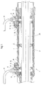
- FIGS. 1 and 2 the area of the cylinder 2 is shown in which a piston 3, which is arranged on a rack shaft 25, can be moved back and forth.
- the piston positions 4 and 5 in the respective end stop areas are shown in dashed lines in FIG. 1.
- the cylinder is closed at both ends by a seal 6, 7.
- the rack shaft 25 is designed in one direction in a manner not shown as a rack and is connected to the pinion of a power steering valve. At both outer ends of the rack shaft, it is connected in a manner not shown to joints of a steering system, not shown.
- a pressure connection 8, 9 is formed at both ends of the cylinder 2, which is formed in a housing. In the exemplary embodiments shown, this is accommodated in an extension 26 which is hood-shaped.
- the pressure lines 18, 19 are inserted into the threaded bores 8, 9 with conventional screw connections. Both sides of the piston can now be pressurized.
- a parallel bore 10, 11 is formed next to each pressure connection 8, 9 in each case to the center of the cylinder and is connected to the pressure connection 8, 9 by a connecting bore 12, 13. If the piston 3 is pressurized via the pressure line 19 and the pressure connection 9, which each lead into the right cylinder chamber, it moves in the image plane seen to the left.
- the pressure port 8 and thus the discharge pressure line 18 is connected to the right cylinder chamber via the parallel bore 10 and the connecting bore 12. This results in partial pressure equalization and the piston moves to the end stop position with reduced pressure.
- the piston By reversing the pressure guide, the piston can be pressurized on the left side and then moves into the right end stop position shown in FIG. 1.
- the parallel and connecting bores 10, 11, 12, 13 are shown tapered in the lower area, i. H. designed as so-called aperture bores 20.
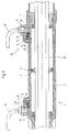
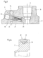
- a check valve 21 is inserted into the connecting bore 12 and the connecting bore 13. This detail is shown in FIG. 3 using the right pressure connection bore 9.
- the check valve opens in the event that the piston moves over the parallel bore 11 when moving into the right stop position shown in FIG. 1.
- the pressure supplied via the pressure line 18 is then returned to the pressure line 19 via the pressure connection 9. If the piston is pressurized on the right side, i. H. Via the pressure line 19 and the pressure connection 9, the check valve 1 closes and the piston approach is fully supported hydraulically, as in steering gears without limit stop device.
- the bores designed as an aperture bore 20, all of which are otherwise closed with closure means known per se, are run over on the inner wall of the cylinder by the piston with its outer seals.
- 4 shows an embodiment.
- this consists of an outer sealing ring 23 and a inner sealing ring 24 is formed, the inner sealing ring applying radial spring forces to bring the outer sealing ring 23 into a stop against the inner wall of the cylinder 2.
- the wide design of the sealing ring is particularly important, which prevents the seals from being damaged by driving over the orifice holes.
- the extension 26 shown in the exemplary embodiment shown is designed in one piece with the housing and rises like a hood or dome around the pressure connections 8 and 9.
- This extension can also be formed by additionally applied and sealingly connected shell elements, the threaded holes, longitudinal and Has cross holes and the like. In this case, bores can also be formed by milled grooves in the extension shell.
Abstract
Description
Die Erfindung betrifft eine hydraulische Zahnstangenlenkung, bei welcher ein Arbeitskolben in einen Hydraulikzylinder geführt ist, welcher eine Endanschlagbegrenzung aufweist, durch welche in einer Endstellung des Arbeitskolbens für das den Arbeitskolben über Druckmittelbohrungen zugeführte Druckmittel ein Weg von dem druckbeaufschlagten Arbeitsraum zu einem Raum geringeren Drucks gebildet wird.The invention relates to a hydraulic rack and pinion steering, in which a working piston is guided into a hydraulic cylinder which has an end stop limitation, by means of which, in an end position of the working piston, a path from the pressurized working space to a lower pressure space is formed for the pressure medium supplied to the working piston via pressure medium bores .
Zahnstangenlenkungen der beschriebenen Art sind aus dem Stand der Technik bekannt.Rack and pinion steering systems of the type described are known from the prior art.
Bei herkömmlichen hydraulischen Zahnstangenlenkungen ohne eine Endanschlagbegrenzung wird der Arbeitskolben durch die Druckbeaufschlagung solange in eine Richtung bewegt, bis irgendwo ein mechanischer Anschlag erreicht ist, beispielsweise ein im Bereich eines Spurstangen-Axialgelenkes und des Lenkungsgehäuses gebildeter Anschlag. Die Lenkung muß daher insgesamt auf eine höhere Belastung ausgelegt werden, was ein hohes Gewicht und entsprechende Produktionskosten zur Folge hat. Darüber hinaus gibt es durch den harten Endanschlag Geräuschentwicklungen, sowie eine hohe Belastung der Hydraulikpumpe.In conventional hydraulic rack and pinion steering systems without an end stop limitation, the working piston is moved in one direction by the pressurization until a mechanical stop is reached somewhere, for example a stop formed in the area of a tie rod axial joint and the steering housing. The steering must therefore be designed overall for a higher load, which has a high weight and corresponding production costs. In addition, there are noises due to the hard end stop, as well as a high load on the hydraulic pump.
Im Stand der Technik sind eine Reihe von Maßnahmen bekannt, die sich unter dem Oberbegriff Kraftausgleichshilfen zusammenfassen lassen. Derartige Vorrichtungen sind bekannt aus der US-PS 4828068, bei welcher eine Bypassleitung die beiden Arbeitsräume des Hydraulikzylinders miteinander verbindet. Weiterhin gehört dazu die DE 3721826 C1, in welcher sowohl ein Servolenkventil als auch die Arbeitsräume des Hydraulikzylinders mit einer Drosselstellenanordnung verbunden sind. Schließlich gehört dazu die DE 3929572 A1, bei welcher ebenfalls die beiden Arbeitsräume mittels einer Längsbohrung verbunden sind, die an beiden Enden gegenläufig gesteuerte Rückschlagventile aufweist. Alle genannten Vorrichtungen dienen dem Zweck, insbesondere die Lenkunterstützung in der Endanschlagposition zu verringern.A number of measures are known in the prior art which can be summarized under the generic term force balancing aids. Such devices are known from US-PS 4828068, in which a bypass line connects the two working spaces of the hydraulic cylinder with each other. This also includes DE 3721826 C1, in which both a Power steering valve and the working spaces of the hydraulic cylinder are connected to a throttle valve arrangement. Finally, this includes DE 3929572 A1, in which the two working spaces are likewise connected by means of a longitudinal bore which has check valves which are controlled in opposite directions at both ends. All the devices mentioned serve the purpose, in particular to reduce the steering assistance in the end stop position.
Die genannten Vorrichtungen können jedoch die beschriebenen Endanschlagsprobleme nicht beheben.However, the devices mentioned cannot solve the described end stop problems.
Aus der GB-PS 766784 ist eine gattungsgemäße hydraulische Zahnstangenlenkung bekannt, bei welcher der Arbeitskolben im Endanschlagsbereich in in der Innenwandung des Hydraulikzylinders angeordnete vertiefte Nutenbereiche hineinläuft, so daß die hydraulische Dichtung zwischen Kolben und Zylinderwandung aufgehoben wird. Aus der DE 1967046 ist es bekannt, die Druckanschlußbereiche einerseits an den Enden des Zylinders anzuordnen, andererseits auch parallel nahe zur Mitte. Überläuft der Kolben den jeweiligen mittleren Anschlußbereich, können Drucksteuerungen eingreifen und so den Kolben im Endanschlag begrenzen. Aus der DE 4221459 A1 ist eine gattungsgemäße hydraulische Zahnstangenlenkung bekannt, bei welcher entweder ebenfalls die bereits bekannten nutartigen Vertiefungen oder im Gehäuseinneren ausgeführte Sackloch- bzw. Verbindungsbohrungen ausgeführt sind, um zwei zueinander parallele Druckmittelzuführungen von jedem einzelnen Druckmittelanschluß auszuführen.From GB-PS 766784 a generic hydraulic rack and pinion steering is known, in which the working piston in the end stop area runs into recessed groove areas arranged in the inner wall of the hydraulic cylinder, so that the hydraulic seal between the piston and the cylinder wall is broken. From DE 1967046 it is known to arrange the pressure connection areas on the one hand at the ends of the cylinder, and on the other hand also parallel to the center. If the piston overflows the respective middle connection area, pressure controls can intervene and limit the piston in the end stop. From DE 4221459 A1 a generic hydraulic rack and pinion steering system is known, in which either the already known groove-like recesses or blind holes or connection bores made inside the housing are also designed in order to carry out two mutually parallel pressure medium feeds from each individual pressure medium connection.
Alle genannten Vorrichtungen machen aufwendige Gehäusegestaltungen und insbesondere auch aufwendige Bearbeitungen im Inneren des Hydraulikzylinders erforderlich. Die nutenartigen Vertiefungen müssen sorgfältig an der inneren Zylinderwandung ausgebildet werden. Die vorbekannten Bohrungen müssen von innen mit großem Aufwand ausgeführt werden. Die aus der DE 1967046 bekannten Verbindungsleitungen befinden sich im Äußeren und stellen als Bypassleitungen zusätzliche Bauteile dar.All of the devices mentioned make complex housing designs and, in particular, complex machining operations inside the hydraulic cylinder necessary. The groove-like depressions must be carefully formed on the inner cylinder wall. The known bores must be carried out from the inside with great effort. The connecting lines known from DE 1967046 are located on the outside and represent additional components as bypass lines.
Insgesamt sind die vorbekannten hydraulischen Zahnstangenlenkungen in der Herstellung und im Materialbedarf aufwendig. Darüber hinaus können keine Abdichtungs- und Führungsprobleme an der Zylinderinnenwandung berücksichtigt werden. Werden beispielsweise von der Innenwandung aus Bohrungen ausgeführt, so können diese Bohrungen scharfkantig sein, so daß die Dichtungen der Kolben ungewöhnlich schnell abgearbeitet oder gar beschädigt werden, so daß die Standzeit herkömmlicher Zahnstangenlenkungen unbefriedigend ist.All in all, the previously known hydraulic rack and pinion steering systems are complex to manufacture and use of materials. Beyond that, none Sealing and guiding problems on the inner wall of the cylinder must be taken into account. If, for example, bores are made from the inner wall, these bores can be sharp-edged, so that the seals of the pistons are processed unusually quickly or even damaged, so that the service life of conventional rack and pinion steering systems is unsatisfactory.
Ausgehend von diesem Stand der Technik liegt der vorliegenden Erfindung die Aufgabe zugrunde, eine Zahnstangenlenkung der gattungsgemäßen Art dahingehend zu verbessern, daß diese mit geringem wirtschaftlichen Aufwand einfach herstellbar ist.Starting from this prior art, the present invention has for its object to improve a rack and pinion steering of the generic type in such a way that it is easy to manufacture with little economic effort.
Zur technischen Lösung dieser Aufgabe wird eine gattungsgemäße Zahnstangenlenkung weiterentwickelt durch wenigstens eine von der Gehäuseaußenseite ausführbare und verschließbare und über eine Verbindungsleitung mit dem jeweiligen Druckanschluß verbindbare Bohrung im Bereich jeder Druckanschlußbohrung.To solve this problem technically, a generic rack and pinion steering system is further developed by at least one hole in the area of each pressure connection hole that can be executed and closed from the outside of the housing and can be connected to the respective pressure connection via a connecting line.
Durch die erfindungsgemäße Weiterbildung wird die Möglichkeit geschaffen, einfach aufgebaute Gehäuse durch von außen angebrachte Bohrungen mit einer entsprechenden Endanschlagbegrenzung zu versehen. Die Bohrungen werden dann wieder an der Gehäuseaußenseite verschlossen und können im Inneren liegend entsprechende Verbindungssysteme bilden.The further development according to the invention creates the possibility of providing a simply constructed housing with a corresponding end stop limitation by means of holes drilled from the outside. The bores are then closed again on the outside of the housing and can form corresponding connection systems lying on the inside.
Gemäß einem Vorschlag der Erfindung umfaßt die erfindungsgemäße Zahnstangenlenkung eine jeweils zur jeweiligen Druckanschlußbohrung im wesentlichen parallele Bohrung, die in Richtung des jeweils anderen Druckanschlusses versetzt ist. Diese zwei zueinanderliegenden Bohrungen, über den Zylinder der Zahnstangenlenkung also insgesamt vier Bohrungen, liegen im wesentlichen zueinander parallel. Die zwei jeweils außenliegenden, d. h. zum Ende des Zylinders liegenden Bohrungen dienen dem Anschluß der Druckzuführleitungen. Die beiden innenliegenden Bohrungen können mit entsprechenden Verbindungsleitungen mit den Druckanschlüssen verbunden werden. Überläuft der Kolben die jeweils innere Bohrung, werden somit beide Druckanschlüsse miteinander verbunden, so daß eine hydraulische Endanschlagbegrenzung bereitgestellt ist. In vorteilhafter Weise ist der Abstand zwischen den inneren Bohrungen und den Druckanschlußbohrungen jeweils zueinander größer als der Arbeitskolben breit ist. Der Endanschlag liegt dann vor der jeweiligen Druckanschlußbohrung, was eine Bewegung des Kolbens in entgegengesetzter Richtung vereinfacht.According to a proposal of the invention, the rack and pinion steering system according to the invention comprises a bore which is essentially parallel to the respective pressure connection bore and which is offset in the direction of the respective other pressure connection. These two mutually opposite bores, ie a total of four bores over the cylinder of the rack and pinion steering, are essentially parallel to one another. The two bores located on the outside, ie at the end of the cylinder, serve to connect the pressure supply lines. The two internal bores can be connected to the pressure connections using appropriate connecting lines. If the piston overflows the respective inner bore, both pressure connections are thus connected to one another, so that a hydraulic limit stop limitation is provided. Advantageously, the Distance between the inner bores and the pressure connection bores to each other is larger than the working piston is wide. The end stop is then in front of the respective pressure connection bore, which simplifies movement of the piston in the opposite direction.
Gemäß einem weiteren Vorteil der Erfindung wird die Verbindungsleitung im wesentlichen in Kolbenbewegungsrichtung verlaufend ausgebildet. In vorteilhafter Weise ist diese Verbindungsleitung ebenfalls eine von der Gehäuseaußenseite ausgeführte Bohrung.According to a further advantage of the invention, the connecting line is designed to run essentially in the direction of piston movement. Advantageously, this connecting line is also a hole made from the outside of the housing.
In besonders vorteilhafter Weise wird vorgeschlagen, daß die Bohrungen zum Zylinderinneren verjüngt sind. Diese Maßnahme bewirkt, daß die kolbenseitigen Dichtungen nur entlang sehr kleiner Kanten bewegt werden, so daß der Dichtungsverschleiß gering gehalten ist.It is proposed in a particularly advantageous manner that the bores are tapered towards the cylinder interior. This measure has the effect that the piston-side seals are only moved along very small edges, so that the seal wear is kept low.
Gemäß einem weiteren vorteilhaften Vorschlag der Erfindung weist das Gehäuse eine haubenartige Erweiterung im Druckanschlußbereich auf. Diese haubenartige Erweiterung dient der Ausbildung der gewünschten Bohrungen und kann mit einfachen Mitteln hergestellt werden. Diese haubenartige Erweiterung kann nach Ausbildung einer Vertikalbohrung auch nachträglich angesetzt werden und eine Horizontalleitung aufweisen. Der äußere Dichtungsbereich kann mit herkömmlichen Mitteln, Schweißen, Kleben oder dergleichen gebildet werden. Durch diese Maßnahme ist die Herstellung der erforderlichen Leitungen besonders einfach.According to a further advantageous proposal of the invention, the housing has a hood-like extension in the pressure connection area. This hood-like extension serves to form the desired holes and can be produced with simple means. This hood-like extension can also be retrofitted after forming a vertical bore and have a horizontal line. The outer seal area can be formed by conventional means, welding, gluing or the like. This measure makes the production of the necessary lines particularly easy.
Gemäß einem weiteren vorteilhaften Vorschlag der Erfindung ist in wenigstens einer der Bohrungen ein Rückschlagventil angeordnet. Durch die Anordnung des Rückschlagventiles können die unterschiedlichen Bewegungsrichtungen des Kolbens hydraulisch einfach realisiert werden.According to a further advantageous proposal of the invention, a check valve is arranged in at least one of the bores. The arrangement of the check valve makes it easy to implement the different directions of movement of the piston hydraulically.
Mit der Erfindung wird eine mit einfachen Mitteln und wirtschaftlich einfach herstellbare Zahnstangenlenkung vorgeschlagen, die über eine hydraulische Endanschlagbegrenzung verfügt, ohne die aus dem Stand der Technik bekannten Nachteile aufzuweisen.The invention proposes a rack and pinion steering system which can be produced with simple means and is economically simple and which has a hydraulic limit stop limitation without having the disadvantages known from the prior art.
Weitere Vorteile und Merkmale der Erfindung ergeben sich aus der folgenden Beschreibung anhand der Figuren. Dabei zeigen:
- Fig. 1
- eine teilgeschnittene Darstellung des Zylinderbereiches einer Zahnstangenlenkung gemäß einem ersten Ausführungsbeispiel;
- Fig. 2
- eine Darstellung gemäß Fig. 1 eines weiteren Ausführungsbeispiels;
- Fig. 3
- eine Darstellung des Details III in Fig. 2 und
- Fig. 4
- eine Detaildarstellung eines Kolbens.
- Fig. 1
- a partially sectioned representation of the cylinder area of a rack and pinion steering according to a first embodiment;
- Fig. 2
- a representation of FIG 1 of another embodiment.
- Fig. 3
- a representation of the detail III in Fig. 2 and
- Fig. 4
- a detailed representation of a piston.
Bei den in den Figuren 1 und 2 gezeigten Zahnstangenlenkungen 1 ist jeweils der Bereich des Zylinders 2 gezeigt, in welchem ein Kolben 3, welcher auf einer Zahnstangenwelle 25 angeordnet ist, hin und her beweglich ist. Gestrichelt sind die Kolbenpositionen 4 und 5 in den jeweiligen Endanschlagsbereichen in Fig. 1 gezeigt.In the rack and pinion steering systems 1 shown in FIGS. 1 and 2, the area of the
Der Zylinder ist an beiden Enden durch eine Dichtung 6, 7 verschlossen. Die Zahnstangenwelle 25 ist in einer Richtung in nicht gezeigter Weise als Zahnstange ausgebildet und steht mit dem Ritzel eines Servolenkventils in Verbindung. An beiden äußeren Enden der Zahnstangenwelle ist diese in nicht gezeigter Weise mit nicht gezeigten Gelenken eines Lenksystems in Verbindung.The cylinder is closed at both ends by a
An beiden Enden des Zylinders 2, der in einem Gehäuse ausgebildet ist, ist ein Druckanschluß 8, 9 ausgebildet. Dieser ist in den gezeigten Ausführungsbeispielen in einer Erweiterung 26, die haubenförmig ausgebildet ist, untergebracht. Die Druckleitungen 18, 19 werden mit herkömmlichen Schraubanschlüssen in die Gewindebohrungen 8, 9 eingesetzt. Beide Seiten des Kolbens können nunmehr mit Druck beaufschlagt werden. Jeweils zur Zylindermitte versetzt ist neben jedem Druckanschluß 8,9 eine Parallelbohrung 10, 11 ausgebildet, welche durch eine Verbindungsbohrung 12, 13 mit dem Druckanschluß 8,9 in Verbindung steht. Wird der Kolben 3 über die Druckleitung 19 und den Druckanschluß 9, welche jeweils in die rechte Zylinderkammer führen, mit Druck beaufschlagt, so wandert er in Bildebene gesehen nach links. Überläuft er die Parallelbohrung 10, wird über die Parallelbohrung 10 und die Verbindungsbohrung 12 der Druckanschluß 8 und damit die abführende Druckleitung 18 mit der rechten Zylinderkammer verbunden. Es kommt somit zu einem teilweisen Druckausgleich und der Kolben fährt mit reduziertem Druck in die Endanschlagsposition. Durch die Umkehr der Druckführung kann der Kolben auf der linken Seite mit Druck beaufschlagt werden und bewegt sich dann bis in die in Fig. 1 gezeigte rechte Endanschlagsposition.At both ends of the
Die Parallel- und Verbindungsbohrungen 10, 11, 12, 13 sind im unteren Bereich verjüngt dargestellt, d. h. als sogenannte Blendenbohrungen 20 ausgeführt.The parallel and connecting
In Fig. 2 ist zusätzlich zu dem in Fig. 1 gezeigten Ausführungsbeispiel in die Verbindungsbohrung 12 und die Verbindungsbohrung 13 jeweils ein Rückschlagventil 21 eingesetzt. In Fig. 3 ist dieses Detail anhand der rechten Druckanschlußbohrung 9 gezeigt. Das Rückschlagventil öffnet in dem Falle, daß der Kolben bei einer Bewegung in die in Fig. 1 gezeigte rechte Anschlagposition über die Parallelbohrung 11 hinwegläuft. Der über die Druckleitung 18 zugeführte Druck wird dann über den Druckanschluß 9 in die Druckleitung 19 zurückgeführt. Wird der Kolben auf der rechten Seite mit Druck beaufschlagt, d. h. über die Druckleitung 19 und den Druckanschluß 9, so schließt das Rückschlagventil 1 und die Kolbenanfahrt wird hydraulisch voll unterstützt wie bei Lenkgetrieben ohne Endanschlagsbegrenzungs-Einrichtung.In FIG. 2, in addition to the exemplary embodiment shown in FIG. 1, a
Die als Blendenbohrung 20 ausgeführten Bohrungen, die im übrigen sämtlich mit an sich bekannten Verschlußmitteln verschlossen sind, werden an der Zylinderinnenwandung von dem Kolben mit seinen äußeren Dichtungen überfahren. In Fig. 4 ist ein Ausführungsbeispiel dargestellt. Der Kolben 3, der so ausgestaltet ist, daß er einfach auf die Zahnstangenwelle 25 aufsetzbar ist, indem er mit seiner rechten Kante, in welcher eine Nutaussparung ausgebildet ist, auf einem auf die Zahnstangenwelle 25 aufgeschobenen Ring verrastet wird und mit seinem linken, nasenartig vorstehenden Ende in eine Nut einrastet, die in der Zahnstangenwelle 25 ausgebildet ist, weist am äußeren Ende eine Nut zur Aufnahme einer Kolbendichtung 22 auf. Dies ist im gezeigten Ausführungsbeispiel aus einem äußeren Dichtungsring 23 und einem inneren Dichtungsring 24 gebildet, wobei der innere Dichtungsring radiale Federkräfte aufbringt, um den äußeren Dichtungsring 23 in einen Anschlag zur Innenwandung des Zylinders 2 zu bringen. Besonders wesentlich ist dabei die breite Ausführung des Dichtringes, wodurch verhindert wird, daß die Dichtungen durch das Überfahren der Blendenbohrungen nicht beschädigt werden.The bores designed as an aperture bore 20, all of which are otherwise closed with closure means known per se, are run over on the inner wall of the cylinder by the piston with its outer seals. 4 shows an embodiment. The
Die im gezeigten Ausführungsbeispiel ausgeführt Erweiterung 26 ist einstückig mit dem Gehäuse ausgebildet und erhebt sich hauben- oder kuppelartig um die Druckanschlüsse 8 und 9. Diese Erweiterung kann auch durch zusätzlich aufgebrachte und dichtend mit dem Gehäuse verbundene Schalenelemente gebildet sein, die Gewindebohrungen, Längs- und Querbohrungen und dergleichen aufweist. Bohrungen können in diesem Falle auch durch gefräste Nuten in der Erweiterungsschale ausgebildet sein.The
- 11
- ZahnstangenlenkungRack and pinion steering
- 22nd
- Zylindercylinder
- 33rd
- Kolbenpiston
- 44th
- KolbenpositionPiston position
- 55
- KolbenpositionPiston position
- 66
- Dichtungpoetry
- 77
- Dichtungpoetry
- 88th
- DruckanschlußPressure connection
- 99
- DruckanschlußPressure connection
- 1010th
- ParallelbohrungParallel bore
- 1111
- ParallelbohrungParallel bore
- 1212th
- VerbindungsbohrungConnecting hole
- 1313
- VerbindungsbohrungConnecting hole
- 1414
- VerschlußClosure
- 1515
- VerschlußClosure
- 1616
- VerschlußClosure
- 1717th
- VerschlußClosure
- 1818th
- DruckleitungPressure line
- 1919th
- DruckleitungPressure line
- 2020th
- BlendenbohrungAperture hole
- 2121
- Rückschlagventilcheck valve
- 2222
- KolbendichtungPiston seal
- 2323
- AußenringOuter ring
- 2424th
- InnenringInner ring
- 2525th
- ZahnstangenwelleRack shaft
- 2626
- Erweiterungextension
Claims (7)
gekennzeichnet durch
wenigstens eine von der Gehäuseaußenseite ausführbare und verschließbare und über eine Verbindungsleitung mit dem jeweiligen Druckanschluß verbindbare Bohrung im Bereich jeder Druckanschlußbohrung.The invention relates to a hydraulic rack and pinion steering, in which a working piston is guided into a hydraulic cylinder which has an end stop limitation, by means of which, in an end position of the working piston, a path from the pressurized working space to a lower pressure space is formed for the pressure medium supplied to the working piston via pressure medium bores ,
marked by
at least one bore, which can be executed and closed from the outside of the housing and can be connected to the respective pressure connection via a connecting line, in the region of each pressure connection bore.
Applications Claiming Priority (2)
| Application Number | Priority Date | Filing Date | Title |
|---|---|---|---|
| DE19514244 | 1995-04-15 | ||
| DE19514244A DE19514244A1 (en) | 1995-04-15 | 1995-04-15 | Hydraulic rack and pinion steering |
Publications (3)
| Publication Number | Publication Date |
|---|---|
| EP0737610A2 true EP0737610A2 (en) | 1996-10-16 |
| EP0737610A3 EP0737610A3 (en) | 1997-02-12 |
| EP0737610B1 EP0737610B1 (en) | 2000-05-24 |
Family
ID=7759782
Family Applications (1)
| Application Number | Title | Priority Date | Filing Date |
|---|---|---|---|
| EP96104750A Expired - Lifetime EP0737610B1 (en) | 1995-04-15 | 1996-03-26 | Hydraulic rack-and-pinion steering |
Country Status (8)
| Country | Link |
|---|---|
| US (1) | US5868216A (en) |
| EP (1) | EP0737610B1 (en) |
| JP (1) | JPH0986428A (en) |
| KR (1) | KR960037476A (en) |
| BR (1) | BR9601371A (en) |
| CZ (1) | CZ103096A3 (en) |
| DE (2) | DE19514244A1 (en) |
| ES (1) | ES2146805T3 (en) |
Cited By (4)
| Publication number | Priority date | Publication date | Assignee | Title |
|---|---|---|---|---|
| WO2000027686A1 (en) * | 1998-11-11 | 2000-05-18 | Mercedes Benz Lenkungen Gmbh | Valve arrangement for power-assisted steering systems |
| WO2001056862A1 (en) * | 2000-02-05 | 2001-08-09 | Zf Lenksysteme Gmbh | Servo motor with a working piston, in particular for power-assisted steering gear for motor vehicles |
| WO2007045397A1 (en) * | 2005-10-19 | 2007-04-26 | Eaton Fluid Power Gmbh | Servo drive for power assisted steering |
| DE102008027734A1 (en) | 2008-06-11 | 2009-12-17 | Trw Automotive Gmbh | Cylinder/piston unit for active undercarriage stabilization system, has cylinder comprising two end stops for determining axial end stop position of piston, where piston covers opening of chamber in axial stop position |
Families Citing this family (8)
| Publication number | Priority date | Publication date | Assignee | Title |
|---|---|---|---|---|
| DE19725944C1 (en) * | 1997-06-19 | 1998-12-24 | Trw Fahrwerksyst Gmbh & Co | Hydraulic assist motor vehicle steering rack |
| KR20040015500A (en) * | 2002-08-13 | 2004-02-19 | 현대모비스 주식회사 | Rack bar of Power Steering Gearbox |
| FR2857324B1 (en) * | 2003-07-08 | 2006-09-15 | Koyo Steering Europe Kse | BEARING FOR POWER STEERING HYDRAULIC OF MOTOR VEHICLE |
| DE102006004724A1 (en) * | 2006-02-02 | 2007-08-09 | Bayerische Motoren Werke Ag | Booster cylinder for hydraulic power assisted steering system in motor vehicle, has piston at whose both sides working chamber is formed, and hydraulic connections are provided for supply and removal of hydraulic medium |
| KR101407822B1 (en) * | 2013-07-01 | 2014-06-18 | 구광모 | steering wheel hydraulic cylinder of a disinfectant sprinkler |
| DE102014117327A1 (en) * | 2014-11-26 | 2016-06-02 | Robert Bosch Automotive Steering Gmbh | A steering system for a motor vehicle and method for venting a steering system for a motor vehicle |
| WO2018222845A1 (en) * | 2017-05-31 | 2018-12-06 | R.H. Sheppard Co., Inc. | Plunger assembly for a power steering system |
| US20220355854A1 (en) * | 2021-05-04 | 2022-11-10 | Ronald Gene Timmons | Self-centering double ended hydraulic steering cylinder that uses no electronics |
Citations (3)
| Publication number | Priority date | Publication date | Assignee | Title |
|---|---|---|---|---|
| GB1444631A (en) * | 1973-09-04 | 1976-08-04 | Adwest Eng Ltd | Double-acting piston and cylinder means |
| DE1967046A1 (en) * | 1968-05-21 | 1976-09-23 | Southwire Co | PROCESS FOR MANUFACTURING AN ALUMINUM ALLOY WIRE WITH AN ELECTRICAL CONDUCTIVITY OF AT LEAST 61 PERCENT IACS |
| US4828068A (en) * | 1984-02-02 | 1989-05-09 | General Motors Corporation | Hydraulically power assisted steering gear with pressure relief stop |
Family Cites Families (6)
| Publication number | Priority date | Publication date | Assignee | Title |
|---|---|---|---|---|
| US2867129A (en) * | 1953-10-28 | 1959-01-06 | Gen Motors Corp | Fluid power steering valve |
| US3437166A (en) * | 1967-05-17 | 1969-04-08 | Jeffrey Galion Inc | Steering system for vehicles |
| DE1967046U (en) * | 1967-05-29 | 1967-08-24 | Vakutronik Wissenschaftlicher | PNEUMATIC DRIVE WITH DAMPING IN THE END POSITIONS. |
| DE3721826C1 (en) * | 1987-07-02 | 1988-11-17 | Daimler Benz Ag | Servo valve arrangement |
| DE3929572A1 (en) * | 1988-09-10 | 1990-03-15 | Zahnradfabrik Friedrichshafen | Actuating rod for power assisted steering - has non-return valves which allow oil to flow into pressure chambers but not in reverse direction |
| DE4221459A1 (en) * | 1992-06-30 | 1994-01-05 | Teves Gmbh Alfred | Hydraulic servo steering with overload protection - has direct connection between pressure-charged working chamber and pressure connection of other working chamber |
-
1995
- 1995-04-15 DE DE19514244A patent/DE19514244A1/en not_active Withdrawn
-
1996
- 1996-03-26 DE DE59605280T patent/DE59605280D1/en not_active Expired - Fee Related
- 1996-03-26 ES ES96104750T patent/ES2146805T3/en not_active Expired - Lifetime
- 1996-03-26 EP EP96104750A patent/EP0737610B1/en not_active Expired - Lifetime
- 1996-04-09 CZ CZ961030A patent/CZ103096A3/en unknown
- 1996-04-12 US US08/631,531 patent/US5868216A/en not_active Expired - Fee Related
- 1996-04-12 JP JP8091394A patent/JPH0986428A/en active Pending
- 1996-04-12 KR KR1019960010932A patent/KR960037476A/en not_active Application Discontinuation
- 1996-04-15 BR BR9601371A patent/BR9601371A/en not_active IP Right Cessation
Patent Citations (3)
| Publication number | Priority date | Publication date | Assignee | Title |
|---|---|---|---|---|
| DE1967046A1 (en) * | 1968-05-21 | 1976-09-23 | Southwire Co | PROCESS FOR MANUFACTURING AN ALUMINUM ALLOY WIRE WITH AN ELECTRICAL CONDUCTIVITY OF AT LEAST 61 PERCENT IACS |
| GB1444631A (en) * | 1973-09-04 | 1976-08-04 | Adwest Eng Ltd | Double-acting piston and cylinder means |
| US4828068A (en) * | 1984-02-02 | 1989-05-09 | General Motors Corporation | Hydraulically power assisted steering gear with pressure relief stop |
Cited By (5)
| Publication number | Priority date | Publication date | Assignee | Title |
|---|---|---|---|---|
| WO2000027686A1 (en) * | 1998-11-11 | 2000-05-18 | Mercedes Benz Lenkungen Gmbh | Valve arrangement for power-assisted steering systems |
| US6345682B1 (en) | 1998-11-11 | 2002-02-12 | Mercedes Benz Lenkungen Gmbh | Valve arrangement for power-assisted steering systems |
| WO2001056862A1 (en) * | 2000-02-05 | 2001-08-09 | Zf Lenksysteme Gmbh | Servo motor with a working piston, in particular for power-assisted steering gear for motor vehicles |
| WO2007045397A1 (en) * | 2005-10-19 | 2007-04-26 | Eaton Fluid Power Gmbh | Servo drive for power assisted steering |
| DE102008027734A1 (en) | 2008-06-11 | 2009-12-17 | Trw Automotive Gmbh | Cylinder/piston unit for active undercarriage stabilization system, has cylinder comprising two end stops for determining axial end stop position of piston, where piston covers opening of chamber in axial stop position |
Also Published As
| Publication number | Publication date |
|---|---|
| DE19514244A1 (en) | 1996-10-17 |
| CZ103096A3 (en) | 1996-10-16 |
| BR9601371A (en) | 1998-01-13 |
| DE59605280D1 (en) | 2000-06-29 |
| KR960037476A (en) | 1996-11-19 |
| ES2146805T3 (en) | 2000-08-16 |
| JPH0986428A (en) | 1997-03-31 |
| US5868216A (en) | 1999-02-09 |
| EP0737610A3 (en) | 1997-02-12 |
| EP0737610B1 (en) | 2000-05-24 |
Similar Documents
| Publication | Publication Date | Title |
|---|---|---|
| DE1775565C3 (en) | Shock absorber with adjustable damping characteristics | |
| EP0756552B1 (en) | Multi-axle steering system for vehicles | |
| DE3240105A1 (en) | PISTONLESS CYLINDER | |
| DE1074346B (en) | Piston valve | |
| DE102008059436B3 (en) | Hydraulic control valve for controlling double acting working cylinder, has annular channel formed in housing, and recess producing connection of contacts, where dimension of recess is twice larger than another recesse | |
| EP0737610B1 (en) | Hydraulic rack-and-pinion steering | |
| DE102005051324A1 (en) | Flush valve for a hydraulic circuit | |
| DE3013381A1 (en) | Power-assisted steering system ram - has cut=off valves in piston connecting pressure chambers with return connection | |
| EP0764241B1 (en) | Hydraulic power cylinder | |
| EP0049406B1 (en) | Arrangement and modeling of pressure fluid passages in cylinders | |
| EP0669469B1 (en) | Fluid driven rotary actuator | |
| DE4221459A1 (en) | Hydraulic servo steering with overload protection - has direct connection between pressure-charged working chamber and pressure connection of other working chamber | |
| DE3204112C2 (en) | Servo slide valve | |
| DE2747842C2 (en) | ||
| DE3024025C2 (en) | Power steering for vehicles with a servo cylinder with two working spaces | |
| DE2648608A1 (en) | Valve for single or multistage cylinder - has back pressure valve to keep smaller piston in rod of first moving | |
| DE3135098A1 (en) | Valve construction comprising a pump control or regulating valve and a relief arrangement | |
| DE2725538C3 (en) | Power-assisted rack and pinion steering for motor vehicles | |
| DE1755697B2 (en) | Hydraulic power steering device for motor vehicles | |
| EP1135614A1 (en) | Releasable check valve for very high system pressures | |
| DE3104989A1 (en) | SERVO CYLINDER | |
| DE102008059437B3 (en) | Hydraulic control valve for controlling operating cylinder, has control spools, where each spool is associated with linear variable differential transformer and hydraulic pilot controller coupled to system, for separate control of spools | |
| DE3204303A1 (en) | HYDRAULIC CYLINDER | |
| DE19757157C2 (en) | Hydraulic linear drive | |
| DE2519973C3 (en) | Relief valve |
Legal Events
| Date | Code | Title | Description |
|---|---|---|---|
| PUAI | Public reference made under article 153(3) epc to a published international application that has entered the european phase |
Free format text: ORIGINAL CODE: 0009012 |
|
| AK | Designated contracting states |
Kind code of ref document: A2 Designated state(s): DE ES FR GB IT SE |
|
| PUAL | Search report despatched |
Free format text: ORIGINAL CODE: 0009013 |
|
| AK | Designated contracting states |
Kind code of ref document: A3 Designated state(s): DE ES FR GB IT SE |
|
| 17P | Request for examination filed |
Effective date: 19970226 |
|
| 17Q | First examination report despatched |
Effective date: 19981130 |
|
| GRAG | Despatch of communication of intention to grant |
Free format text: ORIGINAL CODE: EPIDOS AGRA |
|
| GRAG | Despatch of communication of intention to grant |
Free format text: ORIGINAL CODE: EPIDOS AGRA |
|
| GRAH | Despatch of communication of intention to grant a patent |
Free format text: ORIGINAL CODE: EPIDOS IGRA |
|
| GRAH | Despatch of communication of intention to grant a patent |
Free format text: ORIGINAL CODE: EPIDOS IGRA |
|
| GRAA | (expected) grant |
Free format text: ORIGINAL CODE: 0009210 |
|
| AK | Designated contracting states |
Kind code of ref document: B1 Designated state(s): DE ES FR GB IT SE |
|
| REF | Corresponds to: |
Ref document number: 59605280 Country of ref document: DE Date of ref document: 20000629 |
|
| GBT | Gb: translation of ep patent filed (gb section 77(6)(a)/1977) |
Effective date: 20000612 |
|
| ET | Fr: translation filed | ||
| ITF | It: translation for a ep patent filed |
Owner name: RACHELI & C. S.R.L. |
|
| REG | Reference to a national code |
Ref country code: ES Ref legal event code: FG2A Ref document number: 2146805 Country of ref document: ES Kind code of ref document: T3 |
|
| PGFP | Annual fee paid to national office [announced via postgrant information from national office to epo] |
Ref country code: GB Payment date: 20010202 Year of fee payment: 6 |
|
| PGFP | Annual fee paid to national office [announced via postgrant information from national office to epo] |
Ref country code: FR Payment date: 20010301 Year of fee payment: 6 |
|
| PGFP | Annual fee paid to national office [announced via postgrant information from national office to epo] |
Ref country code: ES Payment date: 20010315 Year of fee payment: 6 |
|
| PG25 | Lapsed in a contracting state [announced via postgrant information from national office to epo] |
Ref country code: SE Free format text: LAPSE BECAUSE OF NON-PAYMENT OF DUE FEES Effective date: 20010327 |
|
| PLBE | No opposition filed within time limit |
Free format text: ORIGINAL CODE: 0009261 |
|
| STAA | Information on the status of an ep patent application or granted ep patent |
Free format text: STATUS: NO OPPOSITION FILED WITHIN TIME LIMIT |
|
| 26N | No opposition filed | ||
| EUG | Se: european patent has lapsed |
Ref document number: 96104750.3 |
|
| REG | Reference to a national code |
Ref country code: GB Ref legal event code: IF02 |
|
| PG25 | Lapsed in a contracting state [announced via postgrant information from national office to epo] |
Ref country code: GB Free format text: LAPSE BECAUSE OF NON-PAYMENT OF DUE FEES Effective date: 20020326 |
|
| PG25 | Lapsed in a contracting state [announced via postgrant information from national office to epo] |
Ref country code: ES Free format text: LAPSE BECAUSE OF NON-PAYMENT OF DUE FEES Effective date: 20020327 |
|
| GBPC | Gb: european patent ceased through non-payment of renewal fee |
Effective date: 20020326 |
|
| PG25 | Lapsed in a contracting state [announced via postgrant information from national office to epo] |
Ref country code: FR Free format text: LAPSE BECAUSE OF NON-PAYMENT OF DUE FEES Effective date: 20021129 |
|
| REG | Reference to a national code |
Ref country code: FR Ref legal event code: ST |
|
| REG | Reference to a national code |
Ref country code: ES Ref legal event code: FD2A Effective date: 20030410 |
|
| PG25 | Lapsed in a contracting state [announced via postgrant information from national office to epo] |
Ref country code: IT Free format text: LAPSE BECAUSE OF NON-PAYMENT OF DUE FEES;WARNING: LAPSES OF ITALIAN PATENTS WITH EFFECTIVE DATE BEFORE 2007 MAY HAVE OCCURRED AT ANY TIME BEFORE 2007. THE CORRECT EFFECTIVE DATE MAY BE DIFFERENT FROM THE ONE RECORDED. Effective date: 20050326 |
|
| PGFP | Annual fee paid to national office [announced via postgrant information from national office to epo] |
Ref country code: DE Payment date: 20090331 Year of fee payment: 14 |
|
| PG25 | Lapsed in a contracting state [announced via postgrant information from national office to epo] |
Ref country code: DE Free format text: LAPSE BECAUSE OF NON-PAYMENT OF DUE FEES Effective date: 20101001 |