EP0737579B1 - Tête à jet d'encre et son procédé de fabrication - Google Patents
Tête à jet d'encre et son procédé de fabrication Download PDFInfo
- Publication number
- EP0737579B1 EP0737579B1 EP96105736A EP96105736A EP0737579B1 EP 0737579 B1 EP0737579 B1 EP 0737579B1 EP 96105736 A EP96105736 A EP 96105736A EP 96105736 A EP96105736 A EP 96105736A EP 0737579 B1 EP0737579 B1 EP 0737579B1
- Authority
- EP
- European Patent Office
- Prior art keywords
- ink
- ink jet
- jet head
- top plate
- array
- Prior art date
- Legal status (The legal status is an assumption and is not a legal conclusion. Google has not performed a legal analysis and makes no representation as to the accuracy of the status listed.)
- Expired - Lifetime
Links
- 238000000034 method Methods 0.000 title claims description 10
- 238000003825 pressing Methods 0.000 claims description 23
- 238000005304 joining Methods 0.000 claims description 7
- 238000000465 moulding Methods 0.000 claims description 7
- 239000011347 resin Substances 0.000 claims description 5
- 229920005989 resin Polymers 0.000 claims description 5
- 239000006096 absorbing agent Substances 0.000 description 13
- 238000007639 printing Methods 0.000 description 9
- 229920001971 elastomer Polymers 0.000 description 7
- 239000003570 air Substances 0.000 description 6
- 230000033001 locomotion Effects 0.000 description 6
- 239000000853 adhesive Substances 0.000 description 5
- 230000001070 adhesive effect Effects 0.000 description 5
- 238000004140 cleaning Methods 0.000 description 5
- 238000007641 inkjet printing Methods 0.000 description 5
- 238000004519 manufacturing process Methods 0.000 description 5
- 238000010276 construction Methods 0.000 description 4
- 239000007788 liquid Substances 0.000 description 4
- 239000000463 material Substances 0.000 description 4
- 239000012260 resinous material Substances 0.000 description 4
- 239000000565 sealant Substances 0.000 description 4
- 238000003860 storage Methods 0.000 description 4
- 210000000078 claw Anatomy 0.000 description 3
- 238000004891 communication Methods 0.000 description 3
- 238000009826 distribution Methods 0.000 description 3
- 230000000694 effects Effects 0.000 description 3
- 238000011084 recovery Methods 0.000 description 3
- 230000002787 reinforcement Effects 0.000 description 3
- 230000017525 heat dissipation Effects 0.000 description 2
- 238000012856 packing Methods 0.000 description 2
- 229920002492 poly(sulfone) Polymers 0.000 description 2
- 238000007789 sealing Methods 0.000 description 2
- 239000000758 substrate Substances 0.000 description 2
- 238000003466 welding Methods 0.000 description 2
- 239000004695 Polyether sulfone Substances 0.000 description 1
- 239000004721 Polyphenylene oxide Substances 0.000 description 1
- 239000004743 Polypropylene Substances 0.000 description 1
- XAGFODPZIPBFFR-UHFFFAOYSA-N aluminium Chemical compound [Al] XAGFODPZIPBFFR-UHFFFAOYSA-N 0.000 description 1
- 229910052782 aluminium Inorganic materials 0.000 description 1
- 239000012080 ambient air Substances 0.000 description 1
- 230000005540 biological transmission Effects 0.000 description 1
- 238000009835 boiling Methods 0.000 description 1
- 229920005549 butyl rubber Polymers 0.000 description 1
- 230000015556 catabolic process Effects 0.000 description 1
- 239000012141 concentrate Substances 0.000 description 1
- 239000004020 conductor Substances 0.000 description 1
- 230000006378 damage Effects 0.000 description 1
- 238000006731 degradation reaction Methods 0.000 description 1
- 238000001514 detection method Methods 0.000 description 1
- 238000007599 discharging Methods 0.000 description 1
- 239000000428 dust Substances 0.000 description 1
- 238000002347 injection Methods 0.000 description 1
- 239000007924 injection Substances 0.000 description 1
- 239000012778 molding material Substances 0.000 description 1
- 239000002245 particle Substances 0.000 description 1
- 238000005192 partition Methods 0.000 description 1
- 229920006393 polyether sulfone Polymers 0.000 description 1
- 229920006380 polyphenylene oxide Polymers 0.000 description 1
- -1 polypropylene Polymers 0.000 description 1
- 229920001155 polypropylene Polymers 0.000 description 1
- 230000000750 progressive effect Effects 0.000 description 1
- 230000002940 repellent Effects 0.000 description 1
- 239000005871 repellent Substances 0.000 description 1
- 239000013464 silicone adhesive Substances 0.000 description 1
- 229920002379 silicone rubber Polymers 0.000 description 1
- 239000004945 silicone rubber Substances 0.000 description 1
- 239000000057 synthetic resin Substances 0.000 description 1
- 229920003002 synthetic resin Polymers 0.000 description 1
- 239000002699 waste material Substances 0.000 description 1
Images


Classifications
-
- B—PERFORMING OPERATIONS; TRANSPORTING
- B41—PRINTING; LINING MACHINES; TYPEWRITERS; STAMPS
- B41J—TYPEWRITERS; SELECTIVE PRINTING MECHANISMS, i.e. MECHANISMS PRINTING OTHERWISE THAN FROM A FORME; CORRECTION OF TYPOGRAPHICAL ERRORS
- B41J2/00—Typewriters or selective printing mechanisms characterised by the printing or marking process for which they are designed
- B41J2/005—Typewriters or selective printing mechanisms characterised by the printing or marking process for which they are designed characterised by bringing liquid or particles selectively into contact with a printing material
- B41J2/01—Ink jet
- B41J2/135—Nozzles
- B41J2/14—Structure thereof only for on-demand ink jet heads
- B41J2/14016—Structure of bubble jet print heads
- B41J2/14024—Assembling head parts
-
- B—PERFORMING OPERATIONS; TRANSPORTING
- B41—PRINTING; LINING MACHINES; TYPEWRITERS; STAMPS
- B41J—TYPEWRITERS; SELECTIVE PRINTING MECHANISMS, i.e. MECHANISMS PRINTING OTHERWISE THAN FROM A FORME; CORRECTION OF TYPOGRAPHICAL ERRORS
- B41J2/00—Typewriters or selective printing mechanisms characterised by the printing or marking process for which they are designed
- B41J2/005—Typewriters or selective printing mechanisms characterised by the printing or marking process for which they are designed characterised by bringing liquid or particles selectively into contact with a printing material
- B41J2/01—Ink jet
- B41J2/135—Nozzles
- B41J2/16—Production of nozzles
- B41J2/1601—Production of bubble jet print heads
- B41J2/1604—Production of bubble jet print heads of the edge shooter type
-
- B—PERFORMING OPERATIONS; TRANSPORTING
- B41—PRINTING; LINING MACHINES; TYPEWRITERS; STAMPS
- B41J—TYPEWRITERS; SELECTIVE PRINTING MECHANISMS, i.e. MECHANISMS PRINTING OTHERWISE THAN FROM A FORME; CORRECTION OF TYPOGRAPHICAL ERRORS
- B41J2/00—Typewriters or selective printing mechanisms characterised by the printing or marking process for which they are designed
- B41J2/005—Typewriters or selective printing mechanisms characterised by the printing or marking process for which they are designed characterised by bringing liquid or particles selectively into contact with a printing material
- B41J2/01—Ink jet
- B41J2/135—Nozzles
- B41J2/16—Production of nozzles
- B41J2/1621—Manufacturing processes
- B41J2/1623—Manufacturing processes bonding and adhesion
-
- B—PERFORMING OPERATIONS; TRANSPORTING
- B41—PRINTING; LINING MACHINES; TYPEWRITERS; STAMPS
- B41J—TYPEWRITERS; SELECTIVE PRINTING MECHANISMS, i.e. MECHANISMS PRINTING OTHERWISE THAN FROM A FORME; CORRECTION OF TYPOGRAPHICAL ERRORS
- B41J2/00—Typewriters or selective printing mechanisms characterised by the printing or marking process for which they are designed
- B41J2/005—Typewriters or selective printing mechanisms characterised by the printing or marking process for which they are designed characterised by bringing liquid or particles selectively into contact with a printing material
- B41J2/01—Ink jet
- B41J2/135—Nozzles
- B41J2/16—Production of nozzles
- B41J2/1621—Manufacturing processes
- B41J2/1632—Manufacturing processes machining
-
- B—PERFORMING OPERATIONS; TRANSPORTING
- B41—PRINTING; LINING MACHINES; TYPEWRITERS; STAMPS
- B41J—TYPEWRITERS; SELECTIVE PRINTING MECHANISMS, i.e. MECHANISMS PRINTING OTHERWISE THAN FROM A FORME; CORRECTION OF TYPOGRAPHICAL ERRORS
- B41J2/00—Typewriters or selective printing mechanisms characterised by the printing or marking process for which they are designed
- B41J2/005—Typewriters or selective printing mechanisms characterised by the printing or marking process for which they are designed characterised by bringing liquid or particles selectively into contact with a printing material
- B41J2/01—Ink jet
- B41J2/135—Nozzles
- B41J2/16—Production of nozzles
- B41J2/1621—Manufacturing processes
- B41J2/1637—Manufacturing processes molding
-
- B—PERFORMING OPERATIONS; TRANSPORTING
- B41—PRINTING; LINING MACHINES; TYPEWRITERS; STAMPS
- B41J—TYPEWRITERS; SELECTIVE PRINTING MECHANISMS, i.e. MECHANISMS PRINTING OTHERWISE THAN FROM A FORME; CORRECTION OF TYPOGRAPHICAL ERRORS
- B41J2202/00—Embodiments of or processes related to ink-jet or thermal heads
- B41J2202/01—Embodiments of or processes related to ink-jet heads
- B41J2202/11—Embodiments of or processes related to ink-jet heads characterised by specific geometrical characteristics
-
- Y—GENERAL TAGGING OF NEW TECHNOLOGICAL DEVELOPMENTS; GENERAL TAGGING OF CROSS-SECTIONAL TECHNOLOGIES SPANNING OVER SEVERAL SECTIONS OF THE IPC; TECHNICAL SUBJECTS COVERED BY FORMER USPC CROSS-REFERENCE ART COLLECTIONS [XRACs] AND DIGESTS
- Y10—TECHNICAL SUBJECTS COVERED BY FORMER USPC
- Y10T—TECHNICAL SUBJECTS COVERED BY FORMER US CLASSIFICATION
- Y10T29/00—Metal working
- Y10T29/49—Method of mechanical manufacture
- Y10T29/49401—Fluid pattern dispersing device making, e.g., ink jet
Definitions
- the present invention relates to an ink jet head and a method of producing the ink jet head. More particularly, the present invention is concerned with an ink jet head of the type which employs electro-thermal transducers as elements for generating discharge energy. Still more particularly, the present invention pertains to an improved construction for keeping a heater board having the electro-thermal transducers formed thereon and a top plate of the ink jet head in close and tight contact with each other at their joint surfaces.
- an ink jet head has been known in which electro-thermal transducers are used as the elements which generate energy for discharging ink.
- a wiring layer is formed on an exothermic resistor layer so that pairs of electrodes electrically connected to the exothermic resistors are formed.
- ink in each of a plurality of channels is heated by the heat from the associated exothermic element formed between the exothermic resistor layer and the electrodes, so that a bubble of ink is generated in the channel so as to eject an ink droplet from the ejection opening leading from the channel, thereby performing printing.
- One form of the ink heat head of the type described is fabricated by separately preparing a substrate (referred to also as “heater board") on which the plurality of exothermic resistors are formed and a top plate in which a plurality of grooves are formed, and the heater board and the top plate are joined with each other to make close contact with each other so that ink channels (referred to also as “nozzles") corresponding to the exothermic resistors are formed by the grooves in the top plate.
- a substrate referred to also as “heater board”
- nozzles ink channels
- a method of fabricating an ink jet head of the type described, disclosed in United States Patent No. 5095321, employs a heater board as a first member having electro-thermal transducers formed thereon and a top plate as a second member.
- the second member is placed on the first member such that the ink channels are positioned right above the wirings of the electro-thermal transducers, and pressure is applied by a pressing device such as springs so as to keep the first and second members in close contact with each other.
- a top plate 1300 is juxtaposed to a heater board 100 such that the ink channels are aligned with the electro-thermal transducers, and a pressing device such as a device incorporating springs applies pressure load to the top plate 1300 so as to keep these two members in close and right contact with each other.
- the top plate 1300 is made of a synthetic resinous material, because such a material provides a high efficiency of production and because the use of such a material eliminates any risk of rupture of the heater board 100.
- the described known structure suffers from a disadvantage in that it is extremely difficult to keep the initial high degree of flatness of the ink channels constituting the nozzle array, because the top plate 1300 after the forming tends to warp due to characteristic peculiar to the resinous material.
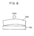
- Fig. 6 illustrates a top plate 1300 warping such that it is convex upward at mid portion of the nozzle array above the level of both end regions of the nozzle array.
- this top plate 1300 is juxtaposed to the heater board 100 and pressed onto the heater board with an adequate level of pressure, close contact between the top plate 1300 and the heater board 100 cannot be obtained at the middle portion of the nozzle array, allowing crosstalk between the adjacent nozzles, i.e., relieve of ejection energy from one to another nozzle, failing to provide high accuracy of ejection of the ink, resulting in serious degradation in the quality of the print.
- warping of the top plate formed from a synthetic resin is one of the factors which reduce the yield of the ink jet head.
- EP-A2-0 636 480 discloses an ink jet head according to the preamble of claim 1, and a method of producing an ink jet head according to the preamble of claim 4.
- an object of the present invention is to provide an ink jet head in which the first and second members mentioned above are held in optimum degree of closeness of contact with each other, so as to eliminate any crosstalk between ink channels, thus ensuring high accuracy of jetting of ink and consequent high quality of printing, thereby overcoming the above-described problems of the known art.
- Another object of the present invention is to provide a method of producing an ink jet head which ensures that the first and second member of the ink jet head are held in optimum closeness of contact with each other despite any warp of one of these members, thereby improving the yield of production of the ink jet head.
- an ink jet head comprising: a first member having a plurality of energy generating elements for generating energy necessary for ejecting ink; a second member having a plurality of grooves separated by land portions, the grooves being for constituting an array of ink channels leading to an array of ink ejecting openings and the land portions being for constituting ink channel walls separating the ink channels; and a pressing member for pressing the first member and the second member to each other thereby joining these members so that the ink channels are formed by cooperation between the first member and the grooves in the second member; wherein the height of the ink channel walls is smaller at both end regions of the array of ink channels than at the central regions of the array of ink channels, and characterized in that: said ink channel walls having smaller height are provided with a deformable projection formed thereon so as to be contactable with said first member.
- a method of producing an ink jet head comprising the steps of: preparing a first member having a plurality of energy generating elements for generating energy necessary for ejecting ink; preparing a second member having a plurality of grooves separated by land portions, the grooves being for constituting an array of ink channels leading to an array of ink ejecting openings and the land portions being for constituting ink channel walls separating the ink channels; preparing a pressing member for pressing the first member and the second member to each other; bringing the first member and the second member into contact with each other such that the energy generating elements are aligned with the grooves; pressing the first member and the second member to each other by the pressing member thereby joining these members so that the ink channels are formed by cooperation between the first member and the grooves in the second; wherein the height of the ink channel walls is smaller at both end regions of the array of ink channels than at the central regions of the array of ink channels, and characterized in that:
- the top plate can be formed with a greater margin or tolerance of warping, so that the yield is improved to reduce the cost of production of the ink jet head.
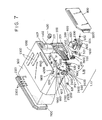
- Figs. 7 to 11 are illustrations of an ink jet system which incorporates an ink jet head embodying the present invention, showing an ink jet unit IJU, an ink jet head IJH, an ink tank IT, an ink jet cartridge IJC, an ink jet apparatus IJA and a carriage HC, as well as the relationship therebetween.
- the ink jet cartridge IJC is a disposable cartridge which is detachably fixed to and carried by the carriage HC which is installed in an ink jet apparatus IJA.
- the ink jet cartridge IJC is located on and fixed to the carriage HC by cooperation between the locating means of the carriage HC which will be described later and electrical contacts provided on the carriage HC.
- the ink jet unit is bubble jet type unit employing electro-thermal transducers which are activated to generate heat which cause film boiling of ink in accordance with electrical signals thereby performing printing.
- a heater board 100 has an Si substrate carrying a plurality of electro-thermal transducers (ejection heaters) disposed in the form of an array, the transducers being formed by a film-forming technic together with conductor wires such as of Al (aluminum) for supplying the transducers with electrical power.
- electro-thermal transducers ejection heaters
- conductor wires such as of Al (aluminum) for supplying the transducers with electrical power.
- a wiring board 200 has wirings corresponding to the wirings on the heater board 100 and connected thereto by, for example, wire bonding technic.
- the wiring board 200 also has pads 201 connected to the ends of the wirings and adapted to be supplied with electrical signals from the main part of an apparatus such as a printer.
- a grooved top plate 1300 has grooves which are to form ink channels and which are separated from land portions serving as ink channel walls.
- the top plate 1300 also has a recess which serves as a common ink chamber from which ink is supplied to the respective ink channels.
- the top plate 1300 is fabricated by molding an orifice plate 400 having orifice ports or ejection openings corresponding to the ink channels integrally with an ink filling port 1500 which receives ink from the ink tank IT and delivers the same to the above-mentioned common ink chamber.
- polysulfone is used as the material from which the top plate 1300 is integrally molded, although the invention does not exclude the use of other types of resin can be used as the molding material.
- a metallic support member 300 provides a back-up surface for supporting the wiring board 200, and serves as a bottom plate of the ink jet unit.
- Numeral 500 denotes a spring serving as a pressing member for pressing the heater board 100 into contact with the top plate 1300.
- the pressing spring 500 has a substantially M-shaped cross-section taken along a plane parallel to the arraying direction of the ink channels, with a mid portion projected towards the top plate so as to lightly press the portion of the top plate 1300 where the common ink chamber is formed.
- the pressing spring 500 also has a front tab portion 501 which exerts and concentrates pressure along a line on a region of the ink channel array, preferably a region in the vicinity of the ejection openings.
- the arrangement is such that the legs of the pressing spring 500 extend through the apertures 3121 formed in the supporting member 300 into engagement with the back side of the supporting member 300, whereby the heater board 100 and the top plate 1300 are securely joined with each other by the concentrated pressure exerted by the main part of the pressing spring 500 and the front tab 501.
- the supporting member 300 has locating holes 312, 1900 and 2000 for engagement with a pair of locating projections 1012 on the ink tank IT and locating/welding projections 1800, 1801 provided on the ink tank IT.
- the supporting member 300 is also provided at its back side with locating projections 2500 and 2600 for locating the carriage HC with respect to the ink jet apparatus IJA.
- the supporting member 300 is provided with a hole 320 adapted to be penetrated by a later-mentioned ink supply tube 2200 through which ink is supplied from the ink tank IT.
- the fixing of the wiring board 200 to the supporting member 300 is made by bonding using an adhesive or the like.
- Recesses 2400, 2400 are formed in the portions of the supporting member 300 adjacent to the locating projections 2500, 2600. In the assembled state of the ink jet cartridge IJC as shown in Fig. 8, these recesses 2400, 2400 are disposed on the extensions of parallel grooves 3000, 3001 formed in three sides of the head end region, and serve to prevent any foreign matter such as dust particles and ink from reaching the locating projections 2500, 2600.
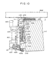
- a cover member 800 which, as will be seen from Fig. 10, constitutes an outer wall of the ink jet cartridge IJC and, in cooperation with the ink tank IT, defines a space for accommodating the ink jet unit IJU.
- the parallel grooves 3001 are formed in an ink supplying member 600.
- the ink supplying member 600 has an ink conduit 1600 communicating with the aforementioned ink supplying tube 2200 and cantilevered at the end adjacent to the ink supplying tube 2200.
- a sealing pin 602 is inserted in order to ensure the capillary action in the region between the fixed end of the ink conduit 1600 and the ink supplying tube 2200.
- Numeral 601 designates a packing which provides a seal in the junction between the ink tank IT and the ink supplying tube 2200, while 700 designates a filter provided in the end of the ink supplying tube 2200 adjacent to the ink tank IT.
- the ink supplying member 600 is formed by molding and, hence, can be produced at low cost with high dimensional precision, thus minimizing error in production.
- the cantilevered structure of the conduit 1600 eliminates any variation in the state of pressure contact between the free end of the conduit 1600 and the aforesaid ink filling port 1500, despite any slight dimensional error which may be caused when ink supplying member 600 is mass-produced.
- a liquid tight communication is achieved simply by supplying a sealant from the ink supplying member, while the free end of the conduit is held in pressure contact with the ink filling port 1500.
- the fixing of the ink supplying member 600 to the supporting member 300 can easily be achieved by setting the ink supplying member 600 on the supporting member 300 with the locating pins (not shown) on the back side of the ink supplying member 600 inserted into corresponding locating holes 1901, 1902 formed in the supporting member 300, and fusing and welding the portions of these pins projecting from the back surface of the supporting member 300.
- the fused ends of the pins slightly project from the back side of the supporting member 300 but such slight projections do not hamper correct positioning of the ink jet unit IJU because such projections are accommodated by recesses (not shown) formed in the ink jet unit mounting surface of the ink tank IT.
- the ink tank IT has a cartridge main structure 1000 having an ink jet unit mounting surface for mounting the ink jet unit IJU, the main structure 1000 being opened at its side opposite to the ink jet unit mounting surface.
- the ink tank IT further has an ink absorber 900 which is placed inside the main structure, and a cover member 1100 which closes the above-mentioned opening after the ink absorber is placed in the cartridge main structure 1000.
- the ink absorber 900 placed in the cartridge main structure 1000 is adapted to be impregnated with ink.
- Numeral 1200 denotes an ink supplying port for supplying the ink to the ink jet unit IJU composed of the aforementioned components 100 to 600.
- ribs 2300 are formed on the inner surface of the main structure 1000 and, at the same time, partial or discontinuous ribs 2301, 2302 are formed on the inner surface of the cover member 1100, so that an air space is formed inside the tank leading from the vent hole 1401 to the ink supplying port 1200 including the region which is remotest from the ink supplying port 1200.
- the filling of the tank with the ink i.e., supply of the ink to the absorber, is preferably executed through the ink supplying port 1200, in order to uniformly impregnate the absorber with the ink. This method is practically effective.
- ribs 2300 provided on the rear wall of the ink tank portion of the cartridge main structure 1000, so that the absorber is prevented from closely contacting the inner surface of the above-mentioned rear wall.
- the partial ribs 2301, 2302 are provided on the portions of the inner surface of the cover member 1100 which are on the extensions of the ribs 2300. Since these partial ribs are segmented, they provide grater volume of the air space than that provided by the ribs 2300.
- the partial ribs 2301, 2302 are distributed over an area which is not greater than half of the entire area of the cover member 1100.
- the ink can be stably induced by capillary action to the ink supplying port 1200, even from the corner region which is remotest from the ink supplying port 1200.
- vent hole 1401 provides communication between the interior of the ink tank and the ambient air.
- a liquid repellent member disposed inside the vent hole 1401 serves to prevent ink from spilling out from the vent hole 1400.
- the ink tank IT having the described construction defines therein a rectangular parallelopiped ink storage space, with the longer sides of the rectangle presenting the side faces of the tank.
- the above-described arrangement of the ribs therefore can be particularly effective.
- the ink storage space has its longer side extending in the direction of movement of the carriage, or when the same is cubic, it is advisable to provide the ribs on the entire area of the cover member 1100, in order to stabilize the supply of the ink from the absorber 900.
- the ink storage space has a rectangular parallelopiped configuration. When such a configuration is adopted, it is important that the ribs which perform the above-described function are provided on the portions of two surfaces adjacent each corner of the space, so that the stored ink can be fully used for the printing without waste.
- the internal ribs of the ink tank used in the described embodiment are disposed at a substantially constant spacing in the direction of thickness of the ink absorber which also has a rectangular parallelopiped configuration.
- Such an arrangement of the ribs is important in order that the atmospheric pressure is uniformly distributed over the entire part of the ink absorber so as to ensure that the ink is completely consumed away to the last drip thereof.
- An imaginary arc is drawn on the rectangular top plane of the rectangular parallelopiped configuration, centered at a point on which the ink supplying port 1200 is projected and with a radius which equals to the length of the longer side of the rectangle.
- the ribs are disposed on the portion of the ink tank inner surface which is outside the above-mentioned arc.
- the position of the vent hole may be changed from the illustrated position, provided that it can introduce air to the region where the ribs are disposed.
- the back face of the ink cartridge IJC opposite to the ink jet head IJH is flattened so as to minimize the space occupied by the ink jet cartridge IJC when the latter is mounted in the apparatus, while maximizing the ink storage capacity.
- This feature contributes to reduction in the size of the whole apparatus and reduces the frequency of renewal of the cartridge.
- the illustrated embodiment makes an effete use of the space behind the ink jet unit IJU secured to the ink tank IT. Namely, a projecting part in which the vent hole 1401 is formed is installed in this space. The internal cavity of this projecting part constitutes an atmospheric pressure supply chamber 1402 which spans the entire thickness of the absorber 900.
- the ink jet cartridge of this embodiment offers advantages which can never be achieved by known cartridges.
- the atmospheric pressure supply chamber 1402 in this embodiment is much greater in size than those in the known cartridges of the kind described. Since the atmospheric pressure communication port 1401 is disposed near the upper end of the atmospheric pressure supply chamber 1402, ink which has happened to flow out of the absorber due to any accident can be preserved in the atmospheric pressure supply chamber 1402 and then absorbed again by the absorber, without leaking to the exterior of the cartridge. It is thus possible to obtain a cartridge which can avoid wasting of the ink.
- Fig. 9 shows the surface of the ink tank IT on which the ink jet unit IJU is to be mounted.
- a straight line L1 is assumed to extend in parallel with the bottom surface of the tank IT or a reference plane on a surface of the carriage, past a point which is substantially midst the array of the ink ejection openings of the orifice plate 400.
- the aforementioned locating projections 1012 engaging the holes 312 formed in the supporting member 300 are positioned on this straight line L1.
- the height of the locating projections 1012 is slightly smaller than the thickness of the supporting member 300.
- the supporting member 300 is correctly located by the engagement between its holes 312 and the locating projections 1012.
- a claw 2100 for engagement with an orthogonal engaging surfaces 4002 of a locating hook 4001 on the carriage HC for locating the ink tank IT is provided on the extension of the above-mentioned line L1, so that the locating force for locating the ink tank with respect to the carriage acts on the planar region which contains this line L1 and which is parallel to the above-mentioned reference plane.
- This arrangement is effective in that the positioning precision of the ink tank IT as a single component is equivalent to the positional precision of the ejection openings of the ink jet head IJH, as will be explained later in connection with Fig. 10.
- the projections 1800 and 1801 provided on the ink tank IT corresponding to the fixing holes 1900 and 2000 formed in the supporting member 300 for fixing the supporting member 300 to a side wall of the ink tank, have a length greater than the length of the aforesaid projection 1012, so that the projections 1800 and 1801 penetrate the supporting member 300 to project therefrom.
- the portions of these projections projecting from the supporting member 300 is thermally fused and welded, whereby the supporting member 300 is fixed to the side face of the ink tank IT.
- Two lines perpendicular to the above-mentioned line L1 are assumed: namely, a line L3 which passes the projection 1800 and a line L2 which passes the projection 1801.
- a point which is substantially on the center of the aforesaid supplying port 1200 is positioned on the line L3. This positional relationship is preferred because it serves to stabilize the state of connection between the port 1200 of the supplying section and the supplying tube 2200, against any load which otherwise may act to disconnect the supplying tube due to application of impact such as by dropping of the cartridge.
- the lines L2 and L3 do not overlap, and the projections 1800 and 1801 are arranged around the projection 1012 which is provided at the ejecting side of the ink jet head IJH. These projections 1800 and 1801 therefore produce an effect to assist correct positioning of the ink jet head IJH with respect to the tank.
- a curve indicated by L4 represents the position of the outer wall of the ink supplying member 600 in the assembled state. Since the projections 1800 and 1801 are disposed along the curve L4, they provide strength and positional accuracy against the weight of the end portion of the ink jet head IJH.
- Numeral 2700 denotes a collar provided on an end of the ink tank IT and adapted to be received in an opening formed in a front panel 4000 of the carriage, so as to hold the ink tank IT against any extraordinary condition which may cause a large deviation of the ink tank.
- Numeral 2101 designates a stopper for preventing the ink jet cartridge IJC from coming off the carriage HC through engagement with a bar (not shown) provided on the carriage HC.
- the stopper 2101 is positioned below the bar on the carriage HC so that, when an unintentional upward force is applied to the ink jet cartridge IJC in the swung state, the stopper 2101 engages with the bar so as to serve as a protection member by preventing the ink jet cartridge IJC from coming off the carriage HC, whereby the ink cartridge IJC is held on the carriage HC without being therefrom.
- the cover 800 is attached to the ink tank IT after the mounting of the ink jet unit IJU, so that the ink jet unit IJU is encased except for the lower side which remains open.
- the ink jet cartridge IJC is placed on the carriage HC, the lower open end is positioned in the close proximity of the carriage HC, so that the ink jet unit IJU is materially encased in a closed space.
- the heat generated from the ink jet head IJH is effectively dissipated to the air in this closed space but such heat causes a slight rise of the air temperature in this space during long continuous use of the ink jet system.
- a slit 1700 of a width smaller than the width of this closed space is formed in the top wall of the ink jet cartridge IJC, whereby a uniform temperature distribution is achieved over the entire portion of the unit IJU without being affected by environment, while preventing excessive rise of temperature.
- the ink is supplied from the interior of the cartridge into the ink supplying tank 600, through the supply port 1200, opening 320 formed in the supporting member 300 and an inlet opening formed in the central rear surface of the supplying tank 600.
- the ink thus introduced into the supplying tank 600 is further introduced into the common liquid chamber through the outlet opening formed in the ink supplying tank, a suitable supplying tube, and an ink inlet opening 150 formed in the top plate 1300.
- Packings of suitable materials such as silicone rubber, butyl rubber and the like are arranged in the junctions between the above-mentioned portions constituting the path of supply of the ink, so as to provide liquid tight seals, whereby a sealed ink supplying passage is formed.
- the top plate 1300 is formed by molding in a mold integrally with the orifice plate 400, from a resinous material resistant to ink, such as polysulfone, polyethersulfone, polyphenylene oxide, polypropylene and so forth.
- a resinous material resistant to ink such as polysulfone, polyethersulfone, polyphenylene oxide, polypropylene and so forth.
- each of the ink supplying member 600, top plate/orifice plate assembly and the ink tank main structure 1000 is molded as a single part, so that the assembly precision is improved, as well as the product quality when the ink jet system is mass-produced. Furthermore, the number of the parts is reduced as compared with the conventional systems, so that the desired characteristics can be developed without difficulty.
- a slit S is formed between the top wall 603 of the ink supplying member 600 and the edge 4008 of the top panel of the ink tank IT having the slit 1700, and a similar slit (not shown) is formed between the bottom wall 604 of the ink supplying member 600 and the head-side edge 4011 of a thin plate member to which the lower cover 800 of the ink tank IT is bonded.
- These slits formed between the ink tank IT and the ink supplying member 600 serve to promote heat dissipation through the aforesaid slit 1700 and serves also as a buffer which prevents any external force applied to the ink tank IT from being directly transmitted to the ink supplying member 600 and, hence, to the ink jet unit IJU.
- a platen roller 5000 is adapted to guide a recording medium P towards the viewer who views the Figure.
- the carriage HC moves along the platen roller 5000.
- the carriage HC has a front plate 4000 of 2 mm thick, provided on the front face of the carriage HC so as to be positioned on the front side of the ink jet cartridge IJC, an electrical connection supporting plate 4003 carrying a flexible plate 4005 and a rubber pad sheet 4007, and the aforesaid locating hook 4001 for fixing the ink jet cartridge IJC to the recording position.
- the flexible sheet 4005 has pads 2011 corresponding to the pads 201 on the wiring board 200 of the ink jet cartridge IJC, and the rubber pad sheet 4007 serves to press the flexible sheet 4005 and, hence, the pads 2011, from the back side of the flexible sheet 4005.
- the front plate 400 has a pair of locating projected surfaces 4010 for engagement with the aforesaid locating projections 2500, 2600 of the supporting member 300 of the cartridge, so that, after the cartridge has been mounted, the front plate 400 bears the force acting on the locating projecting surfaces 4010 perpendicularly thereto.
- a plurality of reinforcement ribs are provided on the side of the front plate adjacent the platen roller, so as to extend in the direction of the above-mentioned force. These ribs serve to form a head protecting projection which projects by a small amount, e.g., about 0.1 mm, from the position L5 of the front face of the cartridge IJC in the mounted state.
- the electrical connection supporting plate 4003 has reinforcement ribs 4004 extending in vertical direction so as to project laterally and arrayed in the direction towards and away from the platen roller 5000.
- the height of lateral projection of the reinforcement ribs 4004 is progressively changed in the direction of the array such that the rib 4004 closest to the platen roller 5000 has the greatest height and the rib 4004 closest to the hook 4001 has the smallest height.
- Such progressive reduction of the projection height serves to enable the cartridge to be mounted with an inclination as illustrated.
- the supporting plate 4003 has a pair of locating surfaces 4006 disposed adjacent to the hook 4001 so as to correspond to the above-mentioned projecting surfaces 4010. These locating surfaces 4006 apply a force to the cartridge in the direction counter to the force exerted on the cartridge by the above-mentioned projecting surfaces 4010.
- the projecting surfaces 4010 and the locating surfaces 4006 cooperate with each other in defining therebetween a pad contact region.
- the rubber pad sheet 4007 mentioned before has rubber projections corresponding to the pads 2011. These locating surfaces serve to directly determine the amounts of deformation of the rubber projections. These locating surfaces make contact with the surface of the wiring board 300 when the ink jet cartridge IJC is fixed at the printing position.
- the pads 201 on the wiring board 300 are arranged in symmetry with respect to the aforementioned line L1, so that the amounts of the robber projections on the rubber pad sheet 4007 are equalized so as to stabilize the pressure of contact between the pads 2011 on the rubber pad sheet 4007 and the pads 201 on the wiring board.
- the pads 201 are arranged in two columns and in two lines at each of upper and lower regions.
- the hook 4001 has an elongated hole for engagement with a fixed shaft 4009. This engagement allows the hook 4001 to rotate counterclockwise from the illustrated position, by virtue of a relative movement of the fixed shaft 4009 with respect to the hook 4001 along the elongated hole.
- the hook 4001 rotated counterclockwise is then moved to the left along the platen roller 5000, thereby locating the ink jet cartridge IJC with respect to the carriage HC.
- Any suitable means can be used for causing the above-described motion of the hook 4001, although a mechanism using a lever action is preferred.
- the ink jet cartridge IJC During the rotation of the hook 4001, the ink jet cartridge IJC, while moving towards the platen roller, brings the locating projections 2500, 2600 to positions where they contact with the locating surfaces 4010. A further leftward movement of the hook 4001 brings the orthogonal hook surface 4002 into close contact with the orthogonal surface of the claw 2100 on the ink jet cartridge IJC and, while this close contact is maintained, the ink jet cartridge IJC is swung in the horizontal plane about the region of contact between the locating surfaces 2500 and 4010, whereby mutual contact between the pads 201 and the pads 2011 is commenced.
- the ink jet cartridge IJC When the hook 4001 is fixed to a predetermined fixing position, the ink jet cartridge IJC is correctly located and held on the carriage, while achieving complete contact between the pads 201 and 2011, complete areal contact between the locating surfaces 2500 and 4010, close contact between the orthogonal surface 4002 on the hook 4001 and the orthogonal surface of the claw 2100, and areal contact between the wiring board 300 and the locating surface 4006.
- Fig. 11 is a schematic perspective view of an internal structure of an ink jet printing apparatus embodying the present invention.
- a lead screw 5005 having a spiral groove 5004 is driven to rotate in one or the other direction by forward or backward operation of a drive motor 5013, through operations of power transmission gears 5011, 5009.
- the carriage HC has a pin (not shown) slidably received in the spiral groove 5004, so that the carriage HC is moved in the direction of the arrow a , or b , in accordance with the operation of the drive motor 5013.
- Numeral 5002 designates a sheet pressing plate which serves to press a paper sheet against the platen roller 5000 over the entire length of the paper sheet in the direction of movement of the carriage.
- a photocoupler is composed of two components 5007 and 5008.
- the photocoupler 5007, 5008 serves as a home position detecting means which, upon detection of a lever 5006 on the carriage, conducts switching of the direction of operation of the motor 5013.
- Numeral 5016 designates a member for supporting a cap member 5022 which caps the front face of the ink jet head IJH.
- a vacuum suction means 5015 induces air from the space concealed by the cap through an opening 5023, so as to apply vacuum to the ink ejecting openings of the ink jet head IJH, thereby performing sucking recovery operation for maintaining good condition of ink ejection from the head.
- Numeral 5017 designates a cleaning blade which is moved back and forth by a member 5019. These members 5017 and 5019 are supported by a main structure supporting plate 5018. Obviously, the illustrated configuration of the cleaning blade is illustrative and any type of known cleaning blades can be used in this embodiment in place of the illustrated cleaning blade 5017.
- Numeral 5012 designates a lever for triggering the sucking recovery operation. This lever is moved in accordance with movement of a cam 5020 which engages with the carriage and is controlled by power transmitted from the drive motor through the known power transmitting means including a clutch or the like.
- the arrangement is such that the capping operation, cleaning operation and sucking recovery operation are executed by the action of the lead screw 5005 when the carriage has been brought to positions which are suitable for the respective operations and which are in a region near the home position.
- This is only illustrative and any suitable mechanism or arrangement may be used to perform these operations at suitable timings.
- Fig. 1 is an enlarged sectional view of a portion of the ink jet head in accordance with the prior art EP-A2-0 636 480, showing particularly the joining surfaces of a top plate 1300 molded from a resinous material and a heater board 100 having an array of electro-thermal transducers which generate thermal energy.
- the top plate 1300 has grooves of a trapezoidal cross-section, so that, when the top plate 1300 and the heater board 100 are joined to each other, nozzles are formed by the grooves.
- Fig. 2 is a diagrammatic side elevational view of the ink jet head in the assembled state, with the top plate 1300 and the heater board 100 joined to each other.
- the grooves which are to form the ejection nozzles are denoted by numeral 11.
- the adjacent grooves 11 are separated from each other by a land portion 13 which serves as the ink channel wall.
- Numeral 12 denote dummy grooves which are formed in both end regions of the top plate 1300 and which do not take part in the ejection of the ink.
- Adjacent dummy grooves 12 are separated by land portions 14 the heights of which are smaller than the land portions which constitute the ink channel walls 13. According to this arrangement, even when the top plate 1300 has been warped such that the surface thereof having the grooves 11, 12 is convex at the central portion as illustrated in Fig.
- each ink channel wall 13 provides a liquid-tight seal between the adjacent ink channels which constitute the ink ejecting nozzles.
- the top plate 1300 having the lands of different heights can be obtained by, for example, molding a top plate blank having lands of uniform height, and then the land portions except for those providing the ink channel walls 13 are suitably ground or cut to have different heights.
- the top plate 1300 is fabricated by molding from a resin into the final configuration, by using a mold having a mold cavity defining land portions of different heights such that the land portions separating the dummy nozzles have heights smaller than those of the land portions which separate the channels or nozzles which actually perform ejection of the ink.
- the latter method enhances tolerance in regard to the warping of the molded top plate, thus offering remarkable increase in the yield of the ink jet head products which employ molded top plates.
- an array of nozzles each being 40 ⁇ m high, 58.5 ⁇ m wide and 400 ⁇ m long, was formed at a pitch of 70.5 ⁇ m.
- the nozzle array had 64 ink ejection nozzles 11 in the central region and 18 dummy nozzles arranged at each end region of the top plate.
- the land portions 13 of the top plate defining 16 dummy nozzles as counted from the outermost dummy nozzle at each end region were cut to reduce their height by 10 ⁇ m, whereby a region 14 where the top plate 1300 does not contact with the heater board 100 at each end of the top plate 1300.
- the top plate thus prepared was placed on the heater board 100 and pressed with moderate pressure load of about 1.5 kg, thus completing an ink jet head assembly.
- the ink jet head thus obtained was mounted on an ink jet printing apparatus embodying the present invention and was subjected to a test printing operation. High quality of print without any unevenness of thickness was confirmed.
- a test also was conducted by using a top plate 1300 warped such that the central crown portion is 20 ⁇ m higher than both ends of the nozzle array.
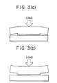
- the top plate 1300 was joined to the heater board 100 under moderate pressure load. In this case, as shown in Fig. 3A, close and tight contact was obtained without any substantial lift, in the region where the ink ejection nozzles are disposed. It was also confirmed that both end regions of the top plate were kept out of contact with the heater board, thus preventing distribution of the pressure load.
- a test was conducted by employing a top plate 1300 warped such that the central region of the plate is at a level of - 20 ⁇ m with respect to both end regions of the nozzle array.
- the top plate 1300 was joined to the heater board 100 under moderate pressure load.
- close and tight contact was obtained in the region where the ink ejection nozzles are disposed and both end regions of the top plate were kept away from the heater board.
- the second embodiment of the present invention employs a deformable projection provided on the end of the land portions having reduced height.
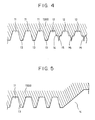
- Fig. 4 is a schematic sectional view of a nozzle forming member, i.e., the top plate 1300, constructed in accordance with the second embodiment of the present invention.
- the configuration and dimensions of the nozzles are the same as those in the first embodiment.
- the land portions defining 16 nozzles out of 18 as counted from the outermost nozzle in each end region were provided with deformable projections formed thereon so as to extend over the entire length of the land portions, i.e., 400 ⁇ m, along these land portions.
- the height of the deformable projections was 20 ⁇ m and the width of the same was not greater than 5 ⁇ m at the base end and not greater than 2 ⁇ m at the free end.
- These deformable projections were formed integrally with the top plate 1300 from a resin by molding.
- the top plate 1300 was placed on the heater board and joined to the same under moderate level of pressure load, whereby an ink jet head was assembled.
- the ink jet head thus assembled was mounted on an ink jet printing apparatus embodying the present invention, and was subjected to test printing. Print of high quality without any unevenness of thickness could be obtained.
- a sealant such as a silicone adhesive, which is used for the purpose of sealing the nozzles and ink chamber (not shown) formed by the top plate 1300 and the heater board 100 is prevented from coming into the nozzles even when the viscosity of the adhesive is very low.
- FIG. 5 is an illustration of the joining surface of a nozzle forming member, i.e., the top plate 1300, used in the third embodiment of the present invention. Shapes and dimensions of the nozzles formed by this nozzle forming member are the same as those of the first embodiment.
- two dummy nozzles are formed at each side of the ejection nozzle region and each end portion of the top plate 1300 outside these dummy nozzle is shaped such that the end extremity of the top plate is 80 ⁇ m apart from the joining surface of the heater board, thus providing a non-contact region where the top plate 1300 does not contact with the heater board 100, at each end of the top plate 1300.
- the top plate 1300 was placed on the heater board and joined to the same under moderate level of pressure load, whereby an ink jet head was assembled.
- the ink jet head thus assembled was mounted on an ink jet printing apparatus embodying the present invention, and was subjected to test printing. Print of high quality without any unevenness of thickness could be obtained.
Landscapes
- Engineering & Computer Science (AREA)
- Manufacturing & Machinery (AREA)
- Particle Formation And Scattering Control In Inkjet Printers (AREA)
Claims (6)
- Tête à jet d'encre comprenant :un premier élément (100) comportant une pluralité d'éléments de génération d'énergie pour générer une énergie nécessaire pour éjecter de l'encre ;un deuxième élément (1300) comportant une pluralité de gorges (11) séparées par des parties planes (13), lesdites gorges étant destinées à constituer un réseau de canaux d'encre conduisant à un réseau d'ouvertures d'éjection d'encre et lesdites parties planes étant destinées à constituer des parois de canal d'encre séparant les canaux d'encre ;un élément de compression pour comprimer ledit premier élément et ledit deuxième élément l'un contre l'autre afin de joindre ces éléments de telle sorte que lesdits canaux d'encre sont formés par coopération entre ledit premier élément et lesdites gorges dans ledit deuxième élément ;la hauteur desdites parois de canal d'encre étant inférieure au niveau des deux régions d'extrémité dudit réseau de canaux d'encre, à celle au niveau des régions centrales dudit réseau de canaux d'encre, et caractérisée en ce quelesdites parois de canal d'encre ayant une hauteur inférieure sont pourvues d'une saillie déformable (15) formée sur elles, de manière à pouvoir être mises en contact avec ledit premier élément (100).
- Tête à jet d'encre selon la revendication 1, dans laquelle les parois de canal d'encre ayant la hauteur inférieure sont disposées dans les régions où une éjection d'encre n'est pas effectuée.
- Tête à jet d'encre selon la revendication 2, dans laquelle ledit deuxième élément est formé à partir d'une résine.
- Procédé de production d'une tête à jet d'encre, comprenant les étapes de :préparation d'un premier élément (100) comportant une pluralité d'éléments de génération d'énergie pour générer une énergie nécessaire pour éjecter de l'encre ;préparation d'un deuxième élément (1300) comportant une pluralité de gorges (11) séparées par des parties planes (13), lesdites gorges étant destinées à constituer un réseau de canaux d'encre conduisant à un réseau d'ouvertures d'éjection d'encre et lesdites parties planes étant destinées à constituer des parois de canal d'encre séparant les canaux d'encre ;préparation d'un élément de compression pour comprimer ledit premier élément et ledit deuxième élément l'un contre l'autre ;mise en contact dudit premier élément et dudit deuxième élément l'un avec l'autre de telle sorte que lesdits éléments de génération d'énergie sont alignés avec lesdites gorges ;compression dudit premier élément et dudit deuxième élément l'un contre l'autre par ledit élément de compression afin de joindre ces éléments de telle sorte que lesdits canaux d'encre sont formés par coopération entre ledit premier élément et lesdites gorges dans ledit deuxième élément ;la hauteur desdites parois de canal d'encre étant inférieure, au niveau des deux régions d'extrémité dudit réseau de canaux d'encre, à celle au niveau des régions centrales dudit réseau de canaux d'encre, et caractérisé en ce quelesdites parois de canal d'encre ayant une hauteur inférieure sont pourvues d'une saillie déformable (15) formée sur elles, de manière à pouvoir être mises en contact avec ledit premier élément (100).
- Procédé de production d'une tête à jet d'encre selon la revendication 4, dans lequel les parois de canal d'encre ayant la hauteur inférieure sont disposées dans les régions où une éjection d'encre n'est pas effectuée.
- Procédé de production d'une tête à jet d'encre selon la revendication 4, dans lequel ledit deuxième élément est formé de manière intégrale par moulage à partir d'une résine.
Applications Claiming Priority (3)
| Application Number | Priority Date | Filing Date | Title |
|---|---|---|---|
| JP7112329A JPH08281960A (ja) | 1995-04-13 | 1995-04-13 | インクジェット記録ヘッド |
| JP11232995 | 1995-04-13 | ||
| JP112329/95 | 1995-04-13 |
Publications (3)
| Publication Number | Publication Date |
|---|---|
| EP0737579A2 EP0737579A2 (fr) | 1996-10-16 |
| EP0737579A3 EP0737579A3 (fr) | 1997-06-11 |
| EP0737579B1 true EP0737579B1 (fr) | 2000-08-02 |
Family
ID=14583961
Family Applications (1)
| Application Number | Title | Priority Date | Filing Date |
|---|---|---|---|
| EP96105736A Expired - Lifetime EP0737579B1 (fr) | 1995-04-13 | 1996-04-11 | Tête à jet d'encre et son procédé de fabrication |
Country Status (4)
| Country | Link |
|---|---|
| US (1) | US6133926A (fr) |
| EP (1) | EP0737579B1 (fr) |
| JP (1) | JPH08281960A (fr) |
| DE (1) | DE69609549T2 (fr) |
Families Citing this family (5)
| Publication number | Priority date | Publication date | Assignee | Title |
|---|---|---|---|---|
| EP1666256B1 (fr) * | 2000-08-09 | 2007-05-23 | Sony Corporation | Tête d'impression, son procédé de fabrication et imprimante |
| TW491770B (en) * | 2001-08-13 | 2002-06-21 | Ind Tech Res Inst | Common module for ink-jet printing head |
| US20040021741A1 (en) * | 2002-07-30 | 2004-02-05 | Ottenheimer Thomas H. | Slotted substrate and method of making |
| US6666546B1 (en) | 2002-07-31 | 2003-12-23 | Hewlett-Packard Development Company, L.P. | Slotted substrate and method of making |
| JP6519391B2 (ja) * | 2015-07-31 | 2019-05-29 | セイコーエプソン株式会社 | 液体噴射ヘッドおよび液体噴射装置 |
Family Cites Families (9)
| Publication number | Priority date | Publication date | Assignee | Title |
|---|---|---|---|---|
| ES2076217T3 (es) * | 1988-10-31 | 1995-11-01 | Canon Kk | Aparato para la impresion por chorros de liquido. |
| US5208604A (en) * | 1988-10-31 | 1993-05-04 | Canon Kabushiki Kaisha | Ink jet head and manufacturing method thereof, and ink jet apparatus with ink jet head |
| EP0578329B1 (fr) * | 1989-09-18 | 1996-03-13 | Canon Kabushiki Kaisha | Tête d'enregistrement à jet d'encre et appareil à jet d'encre ayant celle-ci |
| AU6257490A (en) * | 1989-09-18 | 1991-08-01 | Canon Kabushiki Kaisha | An ink jet apparatus |
| EP0488675A1 (fr) * | 1990-11-28 | 1992-06-03 | Canon Kabushiki Kaisha | Méthode pour la production d'une tête d'enregistrement à jet d'encre et téte d'enregistrement à jet d'encre |
| JP2833875B2 (ja) * | 1991-04-16 | 1998-12-09 | キヤノン株式会社 | インクジェットヘッドの製造方法、及びその製造機 |
| US5432540A (en) * | 1992-02-25 | 1995-07-11 | Citizen Watch Co., Ltd. | Ink jet head |
| JP3168742B2 (ja) * | 1992-12-28 | 2001-05-21 | セイコーエプソン株式会社 | インクジェットヘッドの流路基板の成形金型、及びインクジェットヘッドの流路基板成形金型の製造方法 |
| JP3177100B2 (ja) * | 1993-07-29 | 2001-06-18 | キヤノン株式会社 | インクジェットヘッドおよびインクジェット装置ならびに前記ヘッドの製造方法および前記ヘッドの製造装置 |
-
1995
- 1995-04-13 JP JP7112329A patent/JPH08281960A/ja active Pending
-
1996
- 1996-04-10 US US08/630,751 patent/US6133926A/en not_active Expired - Lifetime
- 1996-04-11 EP EP96105736A patent/EP0737579B1/fr not_active Expired - Lifetime
- 1996-04-11 DE DE69609549T patent/DE69609549T2/de not_active Expired - Lifetime
Also Published As
| Publication number | Publication date |
|---|---|
| EP0737579A3 (fr) | 1997-06-11 |
| DE69609549T2 (de) | 2001-04-19 |
| US6133926A (en) | 2000-10-17 |
| EP0737579A2 (fr) | 1996-10-16 |
| JPH08281960A (ja) | 1996-10-29 |
| DE69609549D1 (de) | 2000-09-07 |
Similar Documents
| Publication | Publication Date | Title |
|---|---|---|
| EP0538842B1 (fr) | Procédé pour la fabrication d'une tête d'enregistrement à jet d'encre | |
| US6059400A (en) | Ink jet apparatus | |
| EP0419191B1 (fr) | Tête d'enregistrement à jet de liquide et appareil d'enregistrement à jet de liquide ayant celle-ci | |
| CA2025536C (fr) | Tete d'enregistrement a jet d'encre et appareil comportant cette tete | |
| US5189443A (en) | Recording head having stress-minimizing construction | |
| JPH07205427A (ja) | プリントヘッドアセンブリ及びその製造方法 | |
| JPH03175051A (ja) | 記録ヘッドカートリッジ、インクタンク及びインクジェット装置 | |
| EP0737579B1 (fr) | Tête à jet d'encre et son procédé de fabrication | |
| US5703632A (en) | Ink jet head orifice plate mounting arrangement | |
| JP3066911B2 (ja) | 記録ヘッド、その保管方法及びそれに用いられるキャップ | |
| JP2637569B2 (ja) | インクジェットヘッド、インクジェットユニット、インクジェットカートリッジ及びインクジェット装置 | |
| JP2660061B2 (ja) | インクジェットヘッド、インクジェットユニット、インクジェットカートリッジ及びインクジェット装置 | |
| JP2670456B2 (ja) | インクジェットヘッド及び該ヘッドを備えたインクジェットカートリッジ及び該カートリッジを搭載したインクジェット記録装置 | |
| JPH04250046A (ja) | インクジェットヘッドユニット,インクジェットヘッドカートリッジおよびインクジェット装置 | |
| JP2692983B2 (ja) | インクジェットヘッド及び該ヘッドを備えたインクジェットカートリッジ及び該カートリッジを搭載したインクジェット記録装置 | |
| JP2714174B2 (ja) | インク収納容器、インク収納容器一体型インクジェットヘッド及びこれを有するインクジェット記録装置 | |
| JPH03101952A (ja) | インクジェットヘッド及び該ヘッドを備えるインクジェットカートリッジ及び該カートリッジを有するインクジェット記録装置 | |
| JP2660062B2 (ja) | インクジェットヘッド、インクジェットユニット、インクジェットカートリッジ及びインクジェット装置 | |
| JP2608333B2 (ja) | インクジェット記録ヘッド | |
| JP2660063B2 (ja) | インクジェットヘッド、インクジェットユニット、インクジェットカートリッジ及びインクジェット装置 | |
| JP2714175B2 (ja) | インクジェット記録ヘッド | |
| EP0420469B1 (fr) | Cartouche pour imprimante à jet d'encre et dispositif à jet d'encre | |
| JP2660059B2 (ja) | インクジェットユニット及びインクジェットカートリッジ並びにインクジェット装置 | |
| JPH05138896A (ja) | インクジエツトヘツド,インクジエツトカートリツジおよびインクジエツト記録装置 | |
| JPH04247946A (ja) | インクジェット記録ヘッドおよびインクジェット記録装置 |
Legal Events
| Date | Code | Title | Description |
|---|---|---|---|
| PUAI | Public reference made under article 153(3) epc to a published international application that has entered the european phase |
Free format text: ORIGINAL CODE: 0009012 |
|
| AK | Designated contracting states |
Kind code of ref document: A2 Designated state(s): DE FR GB IT |
|
| PUAL | Search report despatched |
Free format text: ORIGINAL CODE: 0009013 |
|
| AK | Designated contracting states |
Kind code of ref document: A3 Designated state(s): DE FR GB IT |
|
| 17P | Request for examination filed |
Effective date: 19971028 |
|
| GRAG | Despatch of communication of intention to grant |
Free format text: ORIGINAL CODE: EPIDOS AGRA |
|
| 17Q | First examination report despatched |
Effective date: 19990712 |
|
| GRAG | Despatch of communication of intention to grant |
Free format text: ORIGINAL CODE: EPIDOS AGRA |
|
| GRAH | Despatch of communication of intention to grant a patent |
Free format text: ORIGINAL CODE: EPIDOS IGRA |
|
| GRAH | Despatch of communication of intention to grant a patent |
Free format text: ORIGINAL CODE: EPIDOS IGRA |
|
| GRAA | (expected) grant |
Free format text: ORIGINAL CODE: 0009210 |
|
| AK | Designated contracting states |
Kind code of ref document: B1 Designated state(s): DE FR GB IT |
|
| REF | Corresponds to: |
Ref document number: 69609549 Country of ref document: DE Date of ref document: 20000907 |
|
| ET | Fr: translation filed | ||
| ITF | It: translation for a ep patent filed | ||
| PLBE | No opposition filed within time limit |
Free format text: ORIGINAL CODE: 0009261 |
|
| STAA | Information on the status of an ep patent application or granted ep patent |
Free format text: STATUS: NO OPPOSITION FILED WITHIN TIME LIMIT |
|
| 26N | No opposition filed | ||
| REG | Reference to a national code |
Ref country code: GB Ref legal event code: IF02 |
|
| PGFP | Annual fee paid to national office [announced via postgrant information from national office to epo] |
Ref country code: FR Payment date: 20110607 Year of fee payment: 16 |
|
| PGFP | Annual fee paid to national office [announced via postgrant information from national office to epo] |
Ref country code: IT Payment date: 20110412 Year of fee payment: 16 |
|
| REG | Reference to a national code |
Ref country code: FR Ref legal event code: ST Effective date: 20121228 |
|
| PG25 | Lapsed in a contracting state [announced via postgrant information from national office to epo] |
Ref country code: FR Free format text: LAPSE BECAUSE OF NON-PAYMENT OF DUE FEES Effective date: 20120430 Ref country code: IT Free format text: LAPSE BECAUSE OF NON-PAYMENT OF DUE FEES Effective date: 20120411 |
|
| PGFP | Annual fee paid to national office [announced via postgrant information from national office to epo] |
Ref country code: GB Payment date: 20140414 Year of fee payment: 19 |
|
| PGFP | Annual fee paid to national office [announced via postgrant information from national office to epo] |
Ref country code: DE Payment date: 20140430 Year of fee payment: 19 |
|
| REG | Reference to a national code |
Ref country code: DE Ref legal event code: R119 Ref document number: 69609549 Country of ref document: DE |
|
| GBPC | Gb: european patent ceased through non-payment of renewal fee |
Effective date: 20150411 |
|
| PG25 | Lapsed in a contracting state [announced via postgrant information from national office to epo] |
Ref country code: GB Free format text: LAPSE BECAUSE OF NON-PAYMENT OF DUE FEES Effective date: 20150411 Ref country code: DE Free format text: LAPSE BECAUSE OF NON-PAYMENT OF DUE FEES Effective date: 20151103 |