EP0737117B1 - Verfahren und vorrichtung zum angiessen eines endabmessungsnahen metallbandes - Google Patents
Verfahren und vorrichtung zum angiessen eines endabmessungsnahen metallbandes Download PDFInfo
- Publication number
- EP0737117B1 EP0737117B1 EP95903251A EP95903251A EP0737117B1 EP 0737117 B1 EP0737117 B1 EP 0737117B1 EP 95903251 A EP95903251 A EP 95903251A EP 95903251 A EP95903251 A EP 95903251A EP 0737117 B1 EP0737117 B1 EP 0737117B1
- Authority
- EP
- European Patent Office
- Prior art keywords
- casting
- nozzle
- melt
- main chamber
- conveyor belt
- Prior art date
- Legal status (The legal status is an assumption and is not a legal conclusion. Google has not performed a legal analysis and makes no representation as to the accuracy of the status listed.)
- Expired - Lifetime
Links
- 238000000034 method Methods 0.000 title claims description 9
- 238000005058 metal casting Methods 0.000 title 1
- 238000005266 casting Methods 0.000 claims abstract description 31
- 239000002184 metal Substances 0.000 claims abstract description 20
- 239000000155 melt Substances 0.000 claims description 11
- 229910001338 liquidmetal Inorganic materials 0.000 claims description 3
- 238000002844 melting Methods 0.000 claims description 3
- 239000000463 material Substances 0.000 claims 1
- 230000000149 penetrating effect Effects 0.000 claims 1
- 239000000161 steel melt Substances 0.000 claims 1
- 229910000831 Steel Inorganic materials 0.000 abstract description 2
- 239000010959 steel Substances 0.000 abstract description 2
- 230000008018 melting Effects 0.000 description 2
- 230000004888 barrier function Effects 0.000 description 1
- 238000006073 displacement reaction Methods 0.000 description 1
- 239000007788 liquid Substances 0.000 description 1
- 230000000630 rising effect Effects 0.000 description 1
- 238000011144 upstream manufacturing Methods 0.000 description 1
Images


Classifications
-
- B—PERFORMING OPERATIONS; TRANSPORTING
- B22—CASTING; POWDER METALLURGY
- B22D—CASTING OF METALS; CASTING OF OTHER SUBSTANCES BY THE SAME PROCESSES OR DEVICES
- B22D41/00—Casting melt-holding vessels, e.g. ladles, tundishes, cups or the like
- B22D41/14—Closures
-
- B—PERFORMING OPERATIONS; TRANSPORTING
- B22—CASTING; POWDER METALLURGY
- B22D—CASTING OF METALS; CASTING OF OTHER SUBSTANCES BY THE SAME PROCESSES OR DEVICES
- B22D11/00—Continuous casting of metals, i.e. casting in indefinite lengths
- B22D11/06—Continuous casting of metals, i.e. casting in indefinite lengths into moulds with travelling walls, e.g. with rolls, plates, belts, caterpillars
- B22D11/0631—Continuous casting of metals, i.e. casting in indefinite lengths into moulds with travelling walls, e.g. with rolls, plates, belts, caterpillars formed by a travelling straight surface, e.g. through-like moulds, a belt
-
- B—PERFORMING OPERATIONS; TRANSPORTING
- B22—CASTING; POWDER METALLURGY
- B22D—CASTING OF METALS; CASTING OF OTHER SUBSTANCES BY THE SAME PROCESSES OR DEVICES
- B22D11/00—Continuous casting of metals, i.e. casting in indefinite lengths
- B22D11/06—Continuous casting of metals, i.e. casting in indefinite lengths into moulds with travelling walls, e.g. with rolls, plates, belts, caterpillars
- B22D11/0637—Accessories therefor
- B22D11/064—Accessories therefor for supplying molten metal
Definitions
- the invention relates to a method for casting a metal belt close to its final dimensions onto a belt casting device provided with a melt receptacle and a conveyor belt, in which a metal melt, in particular made of steel, via a closable, pressurizable pouring chamber and connected via a siphon to a pressurizable main chamber a pouring nozzle flows out.
- a metal melt in particular made of steel
- a closable, pressurizable pouring chamber and connected via a siphon to a pressurizable main chamber a pouring nozzle flows out.
- the invention has set itself the goal of demonstrating a method and the necessary device with which a safe displacement of the air is ensured during the start-up phase.
- the invention achieves this aim with the features of claims 1 and 4, respectively.
- the pouring nozzle is filled with liquid melt up to the shut-off located in the area of the mouth.
- Shut-off devices which allow controlled opening are used, in such a way that at the beginning of the opening there is a slot across the entire width of the pouring nozzle.
- the casting pressure is chosen so that the melt emerges at high speed during this first slit-shaped opening of the mouth of the pouring channel.
- the air below the barrier is entrained. This entrainment of the extremely small amounts of air in the region of the mouth of the pouring nozzle is further promoted by the trumpet-like design of the inside of the pouring nozzle facing away from the metal receptacle.
- the pressure resistance at the mouth of the nozzle increased by obstacles.
- the elements used for this are preferably self-consuming so that they can later Do not hinder the casting operation.
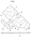
- Figure 1 shows schematically the start-up phase.
- the casting vessel having a main chamber 11 and a pouring chamber 12 is empty, a shut-off element 21 in the pouring nozzle 14 is closed, and the conveyor belt 31 is stationary.
- the main chamber 11 and the pouring chamber 12 are separated by a wall 13.
- the casting vessel is filled with melt in such a way that the melt level in the pouring chamber 12 is raised by negative pressure P o and a differential melting level of ⁇ h A is set in the main chamber.
- the differential level ⁇ h refers to the liquid metal level H that occurs during the casting operation on the conveyor belt or to the inside 16 of the pouring nozzle 14 inclined towards the conveyor belt 31.
- the conveyor belt 31 is put into operation and the shut-off element 21 is opened in the form of a slot.
- the liquid metal M emerges from the casting nozzle and is formed into a casting strand 5.
- the shut-off element 21 is continuously opened during this start-up phase.
- the differential melting level ⁇ h is reduced until it is brought to the operating level height ⁇ h G.
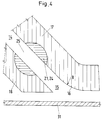
- FIGS. 2 to 4 show the lower section of the pouring nozzle 14 with differently configured shut-off elements 21. Shown in section are the mouth 15 of the wall 17 facing away from the main chamber and of the wall 18 inclined towards the main chamber.
- the inside 16 of the wall 17 is designed like a trumpet. It has a radius R that connects the approximately 45 ° inclined pouring nozzle to the side inclined parallel to the conveyor belt 31.
- an element 41 is arranged on the wall 17. The element 41 serves to increase the pressure resistance and projects into the space between the conveyor belt 31 and the inside 16.
- the shut-off element 21 is a knife gate valve 22 designed, which can be moved via a drive 29 is. In the closed position of the knife gate valve 22 this leans against a level 19 in the wall 18.
- the shut-off element 21 is designed as a flap 23. This leans against a step 19 in the wall 18 in the closed position. In the open position, the flap 23 is pivoted into the wall 17 via a drive (not shown in further detail) such that a plate side forms a plane with the inside 16.
- a shaft 24 is provided as the shut-off element 21, which has a recess 25 which, according to the rotational position of the shaft 24, releases the pouring nozzle unhindered.
- the walls 17 and 18 are for thermal purposes Adjust the same wall thickness.
Landscapes
- Engineering & Computer Science (AREA)
- Mechanical Engineering (AREA)
- Continuous Casting (AREA)
- Coating With Molten Metal (AREA)
- Filling Or Emptying Of Bunkers, Hoppers, And Tanks (AREA)
- Molds, Cores, And Manufacturing Methods Thereof (AREA)
- Treatment Of Steel In Its Molten State (AREA)
- Injection Moulding Of Plastics Or The Like (AREA)
Description
Beim Angießen einer Bandgießeinrichtung zum Herstellen von endabmessungsnahen Metallbändern führen Lufteinschlüsse in der Gießdüse zu erheblichen Behinderungen des Gießbetriebes.
Aus EP 0 534 174 sind Verfahren und die dazu erforderlichen Vorrichtungen bekannt, die ein Verdrängen der Luft aus der Gießdüse und dem vorgeschalteten Bereich bewirken sollen. Hierbei wird einmal vorgeschlagen, im Schmelzeverteiler anfänglich einen Füllstand einzustellen, der maximal der Transportbandebene entspricht und beim Angießen einen solchen Füllstand einzustellen, der die Schmelze aus einer U-förmig gekrümmten Gießdüse verdrängt.
In der Praxis hat sich gezeigt, daß im mittleren oberen Bereich der U-förmig nach unten gekrümmten Gießdüse sich Luft ansammelt. Dies führt im wesentlichen dazu, daß ein nichtkontrollierbarer Anfahrschwall auftritt, der ggf. ein Einfahren des Stranges verhindert.
In der gleichen Schrift wird daher auch noch vorgeschlagen, zwischen dem Schmelzeverteiler und der Gießdüse eine Eingießkammer vorzusehen und beim Angießen - bei gegenüber der Metallschmelze geschlossenem Einlauf der einem Saugheber nachgeschalteten Gießdüse - in der Eingießkammer einen Unterdruck aufzubauen und die Luft in der Gießdüse nach oben zu verdrängen.
Hierbei kommt es zu nicht kontrollierbaren Verengungen in Teilbereichen der Gießdüse, die wiederum nicht gewollten Einfluß auf die Ausbreitung der Metallschmelze auf dem Transportband bewirken.
Die Erfindung erreicht dieses Ziel jeweils mit den Merkmalen der Ansprüche 1 und 4.
Vor dem Anfahren wird die Gießdüse bis zu der sich im Bereich der Mündung befindenden Absperrung mit Flüssigschmelze gefüllt. Es werden Absperrorgane, die ein gesteuertes Öffnen zulassen, eingesetzt, und zwar in der Weise, daß zu Öffnungsbeginn über die gesamte Breite der Gießdüse ein Schlitz vorhanden ist. Der Gießdruck wird dabei so gewählt, daß bei diesem ersten schlitzförmigen Öffnen der Mündung des Gießkanals die Schmelze mit hoher Geschwindigkeit austritt. Hierbei wird die unterhalb der Sperrung sich befindende Luft mitgerissen. Dieses Mitreißen der äußerst geringen Luftmengen im Bereich der Mündung der Gießdüse wird darüber hinaus begünstigt durch die trompetenartige Ausgestaltung der im Metallaufnahmegefäß abgewandten Innenseite der Gießdüse.
Dabei zeigen die
Die Hauptkammer 11 und die Eingießkammer 12 sind durch einen Wall 13 getrennt. Kurz vor Gießbeginn wird das Gießgefäß mit Schmelze gefüllt, und zwar in der Weise, daß der Schmelzenspiegel in der Eingießkammer 12 durch Unterdruck Po angehoben wird und in der Hauptkammer ein Differenzschmelzpegel von ΔhA eingestellt wird. Der Differenzspiegel Δh nimmt Bezug auf den während des Gießbetriebes sich einstellenden Flüssigmetallspiegel H auf dem Transportband bzw. auf die dem Transportband 31 zugeneigte Innenseite 16 der Gießdüse 14.
Zum Gießbeginn wird das Transportband 31 in Betrieb gesetzt und das Absperrelement 21 wird schlitzförmig geöffnet.In einem starken Schwall tritt das Flüssigmetall M aus der Gießdüse aus und wird zu einem Gießstrang 5 ausgeformt. Während dieser Anfahrphase wird das Absperrelement 21 kontinuierlich geöffnet. In Abhängigkeit von der dem Hauptgefäß zugeführten Metallmenge wird der Differenzschmelzspiegel Δh verringert, bis er auf die Betriebspiegelhöhe ΔhG geführt ist.
Am Ende der Mündung 15 ist an der Wand 17 ein Element 41 angeordnet. Das Element 41 dient der Erhöhung des Druckwiderstandes und ragt in den Freiraum zwischen dem Transportband 31 und der Innenseite 16 hinein.
In der Figur 4 ist als Absperrelement 21 eine Welle 24 vorgesehen, welche eine Ausnehmung 25 aufweist, die entsprechend der Drehstellung der Welle 24 die Gießdüse unbehindert freigibt.
Claims (9)
- Verfahren zum Angießen eines endabmessungsnahen Metallbandes (S) auf einer mit einem Schmelzaufnahmegefäß (11,12) und einem Transportband (31) versehenen Bandgießeinrichtung, bei dem eine Metallschmelze, insbesondere aus Stahl, über eine verschließbare, in Unterdruck versetzbare und über einen Syphon mit einer unter Druck versetzbaren Hauptkammer (11) verbundenen Eingießkammer (12) über eine Gießdüse (14) auf das Transportband (31) ausfließt,
gekennzeichnet durch folgende Schritte:a) vor Gießbeginn wird die dem Transportband (31) zugewandte Mündung der Gießdüse (14) verschlossen,b) anschließend werden die Hauptkammer (11) und die Eingießkammer (12) mit Flussigmetall gefüllt, wobei Differenzpegel ΔhA und ΔhG auf einen Wert von ΔhA/ΔhG > 5 in der Hauptkammer bezogen auf den im stationären Betriebszustand auf dem Transportband (31) vorhandenen flüssigen Metallspiegels eingestellt werden,c) zum Gießbeginn wird die Gießdüse (14) auf der dem Hauptgefäß (11) zugeneigten Seite schlitzförmig so geöffnet, daß die abwärts gerichtete Gießgeschwindigkeit des Flüssigmetalls größer ist als die Auftriebsgeschwindigkeit der in der Schmelze eindringenden Gasblasen,d) bei gleichzeitigen kontinuierlichen Öffnen der Gießdüse (14) bis zur völligen Freigabe des Mündungsbereiches wird der Differenzschmelzpegel ΔhG in der Hauptkammer auf einen Wert geringfügig oberhalb des Flüssigmetallspiegels H auf dem Transportband nach dem Saugheberprinzip abgesenkt. - Verfahren zum Angießen nach Anspruch 1,
dadurch gekennzeichnet,daß in der Eingießkammer (12) ein Unterdruck erzeugt wird. - Verfahren zum Angießen nach Anspruch 2 oder 1,
dadurch gekennzeichnet,daß zumindest während des Angießens an der Düsenmündung (14) in Gegenfließrichtung zum Flüssigmetall der Druckwiderstand erhöht wird. - Einrichtung zum Bandgießen eines endabmessungsnahen Metallbandes (S), die ein Transportband (31) und ein aus einer Hauptkammer (11) und einer Eingießkammer (12), die ein den Zugang zug Gießdüse (14) verschließendes Absperrelement besitzt, bestehendes Metallaufnahmegefäß aufweist zur Durchführung des Verfahrens nach Anspruch 1,
dadurch gekennzeichnet,daß die Gießdüse (14) etwa 45° geneigt und im Bereich der Mündung (15) auf der der Hauptkammer (11) abgewandten Innenseite (16) trompetenartig ausgestaltet ist unddaß in der Nähe der Mündung (15) der Gießdüse (14) ein schlitzförmig offenbares Absperrelement (21) vorgesehen ist. - Einrichtung nach Anspruch 4,
dadurch gekennzeichnet,daß das Absperrelement (21) ein Plattenschieber (22) ist. - Einrichtung nach Anspruch 4,
dadurch gekennzeichnet,daß das Absperrelement (21) eine um eine seitlich angeordnete Achse schwenkbare Klappe (23) ist. - Einrichtung nach Anspruch 4,
dadurch gekennzeichnet,daß das Absperrelement (21) aus einer drehbaren Welle (24) aufgebaut ist, die im Bereich des Gießkanals eine mindestens die halbe Wellenquerschnittsfläche umfassende Ausnehmung 25 aufweist. - Einrichtung nach einem der vorgenannten Ansprüche,
dadurch gekennzeichnet,daß am Ausgang der Mündung 15 der der Hauptkammer 11 abgewandten Wand 17 ein Element 41 vorgesehen ist, das den Druckwiderstand in Gegenflußrichtung des Flüssigmetalls M erhöht. - Einrichtung nach Anspruch 8,
dadurch gekennzeichnet,daß das Druckerhöhungselement 41 aus thermisch aufzehrbarem Material, z.B. niedrigschmelzendem Metall, aufgebaut ist.
Applications Claiming Priority (3)
| Application Number | Priority Date | Filing Date | Title |
|---|---|---|---|
| DE4344953A DE4344953C2 (de) | 1993-12-27 | 1993-12-27 | Verfahren und Vorrichtung zum Angießen eines endabmessungsnahen Metallbandes |
| DE4344953 | 1993-12-27 | ||
| PCT/DE1994/001519 WO1995017987A1 (de) | 1993-12-27 | 1994-12-14 | Verfahren und vorrichtung zum angiessen eines endabmessungsnahen metallbandes |
Publications (2)
| Publication Number | Publication Date |
|---|---|
| EP0737117A1 EP0737117A1 (de) | 1996-10-16 |
| EP0737117B1 true EP0737117B1 (de) | 1998-05-20 |
Family
ID=6506515
Family Applications (1)
| Application Number | Title | Priority Date | Filing Date |
|---|---|---|---|
| EP95903251A Expired - Lifetime EP0737117B1 (de) | 1993-12-27 | 1994-12-14 | Verfahren und vorrichtung zum angiessen eines endabmessungsnahen metallbandes |
Country Status (12)
| Country | Link |
|---|---|
| US (1) | US5915459A (de) |
| EP (1) | EP0737117B1 (de) |
| JP (1) | JP3011460B2 (de) |
| KR (1) | KR100314990B1 (de) |
| CN (1) | CN1041498C (de) |
| AT (1) | ATE166265T1 (de) |
| AU (1) | AU680978B2 (de) |
| BR (1) | BR9408424A (de) |
| DE (2) | DE4344953C2 (de) |
| DK (1) | DK0737117T3 (de) |
| ES (1) | ES2116067T3 (de) |
| WO (1) | WO1995017987A1 (de) |
Families Citing this family (7)
| Publication number | Priority date | Publication date | Assignee | Title |
|---|---|---|---|---|
| DE19711116C2 (de) * | 1997-03-05 | 1999-05-12 | Mannesmann Ag | Verfahren und Vorrichtung zum Gießen von dünnen Strängen |
| DE19746728C1 (de) * | 1997-10-13 | 1998-10-29 | Mannesmann Ag | Verfahren zum Angießen eines endabmessungsnahen Metallbandes |
| DE19823440C1 (de) * | 1998-05-19 | 1999-12-09 | Mannesmann Ag | Verfahren und Vorrichtung zum endabmessungsnahen Gießen von Metall |
| DE10333589B9 (de) * | 2003-07-24 | 2010-06-10 | Federal-Mogul Wiesbaden Gmbh & Co. Kg | Verfahren zur Herstellung eines bandförmigen Verbundwerkstoffes für die Gleitlagerherstellung und Vorrichtung zur Durchführung des Verfahrens |
| EP2983658B1 (de) | 2013-03-11 | 2024-05-01 | Sciadonics, Inc. | Lipidzusammensetzungen mit bioaktiven fettsäuren |
| CN114101616B (zh) * | 2021-11-23 | 2023-03-10 | 江苏双友智能装备科技股份有限公司 | 一种全自动铝圆锭浇铸设备及负压铸造工艺 |
| CN114273641B (zh) * | 2021-12-28 | 2023-08-08 | 中科金龙金属材料开发有限公司 | 一种复合线材立式连铸系统及工艺 |
Family Cites Families (15)
| Publication number | Priority date | Publication date | Assignee | Title |
|---|---|---|---|---|
| US1180728A (en) * | 1915-05-08 | 1916-04-25 | Pressed Bearing Company | Method of making lined bearings. |
| FR1488313A (fr) * | 1966-04-22 | 1967-07-13 | Ct De Rech S De Pont A Mousson | Dispositif perfectionné de commande de poches de coulée de liquides |
| JPS5114826A (en) * | 1974-07-30 | 1976-02-05 | Mitsubishi Heavy Ind Ltd | Kono renzokuchuzohoho |
| JPS5829551A (ja) * | 1981-08-14 | 1983-02-21 | Kawasaki Steel Corp | 連続鋳造装置 |
| DE3440237C2 (de) * | 1984-11-03 | 1986-11-06 | Mannesmann AG, 4000 Düsseldorf | Vorrichtung zum Bandstranggießen von Metallen, insbesondere von Stahl |
| DE3521778A1 (de) * | 1985-06-19 | 1987-01-02 | Sundwiger Eisen Maschinen | Verfahren zum herstellen eines metallstranges, insbesondere in form eines bandes oder profils durch giessen und vorrichtung zur durchfuehrung dieses verfahrens |
| DE3810302A1 (de) * | 1988-03-24 | 1989-10-12 | Mannesmann Ag | Giesseinrichtung zur kontinuierlichen herstellung von metallband |
| JPH02155540A (ja) * | 1988-12-08 | 1990-06-14 | Kobe Steel Ltd | 金属薄板の連続鋳造用タンディッシュ |
| DE4000656A1 (de) * | 1990-01-11 | 1991-07-18 | Didier Werke Ag | Schliess- und/oder regelorgan |
| DE4012039A1 (de) * | 1990-04-11 | 1991-10-17 | Mannesmann Ag | Verfahren zur bestimmung und regulierung des badspiegels einer metallschmelze |
| US5063989A (en) * | 1990-06-22 | 1991-11-12 | Armco Inc. | Method and apparatus for planar drag strip casting |
| DE4039959C1 (de) * | 1990-12-14 | 1992-01-23 | Wieland-Werke Ag, 7900 Ulm, De | |
| SE9102022L (sv) * | 1991-07-01 | 1993-01-02 | Stiftelsen Metallurg Forsk | Saett och gjutmaskin foer kontinuerlig gjutning av metallband |
| DE4218587C1 (de) * | 1991-09-27 | 1993-11-04 | Wieland Werke Ag | Verfahren und vorrichtung zur herstellung eines endabmessungsnahen metallbandes |
| DE4319966A1 (de) * | 1993-06-17 | 1994-12-22 | Didier Werke Ag | Eintauchausguß |
-
1993
- 1993-12-27 DE DE4344953A patent/DE4344953C2/de not_active Expired - Fee Related
-
1994
- 1994-12-14 AU AU12186/95A patent/AU680978B2/en not_active Ceased
- 1994-12-14 ES ES95903251T patent/ES2116067T3/es not_active Expired - Lifetime
- 1994-12-14 EP EP95903251A patent/EP0737117B1/de not_active Expired - Lifetime
- 1994-12-14 WO PCT/DE1994/001519 patent/WO1995017987A1/de not_active Ceased
- 1994-12-14 JP JP7517720A patent/JP3011460B2/ja not_active Expired - Lifetime
- 1994-12-14 CN CN94194647A patent/CN1041498C/zh not_active Expired - Fee Related
- 1994-12-14 DK DK95903251T patent/DK0737117T3/da active
- 1994-12-14 AT AT95903251T patent/ATE166265T1/de active
- 1994-12-14 BR BR9408424A patent/BR9408424A/pt not_active Application Discontinuation
- 1994-12-14 DE DE59406056T patent/DE59406056D1/de not_active Expired - Lifetime
- 1994-12-14 US US08/666,512 patent/US5915459A/en not_active Expired - Lifetime
- 1994-12-14 KR KR1019960703414A patent/KR100314990B1/ko not_active Expired - Fee Related
Also Published As
| Publication number | Publication date |
|---|---|
| DE4344953C2 (de) | 1996-10-02 |
| ATE166265T1 (de) | 1998-06-15 |
| DE59406056D1 (de) | 1998-06-25 |
| EP0737117A1 (de) | 1996-10-16 |
| AU1218695A (en) | 1995-07-17 |
| BR9408424A (pt) | 1997-08-26 |
| DE4344953A1 (de) | 1995-06-29 |
| US5915459A (en) | 1999-06-29 |
| CN1041498C (zh) | 1999-01-06 |
| CN1139395A (zh) | 1997-01-01 |
| AU680978B2 (en) | 1997-08-14 |
| KR100314990B1 (ko) | 2002-02-19 |
| ES2116067T3 (es) | 1998-07-01 |
| DK0737117T3 (da) | 1998-10-07 |
| JPH09506551A (ja) | 1997-06-30 |
| WO1995017987A1 (de) | 1995-07-06 |
| JP3011460B2 (ja) | 2000-02-21 |
Similar Documents
| Publication | Publication Date | Title |
|---|---|---|
| DE69323474T2 (de) | Randleisten mit zwei Drähten für die Vorhangsbeschichtung | |
| DE2240643C3 (de) | Düsenstein für Gießpfannen an Metallverdüsungsanlagen | |
| DE69514956T2 (de) | Tauchgiessrohr zum Stranggiessen | |
| DE2902096C2 (de) | ||
| EP0737117B1 (de) | Verfahren und vorrichtung zum angiessen eines endabmessungsnahen metallbandes | |
| DE4218587C1 (de) | Verfahren und vorrichtung zur herstellung eines endabmessungsnahen metallbandes | |
| DE713702C (de) | Behaelter zur Aufnahme von geschmolzenem Glas | |
| DE3924001C2 (de) | Doppelrollen-Stranggießmaschine | |
| DE4322316C1 (de) | Einlaufsystem für eine Aluminiumstranggußanlage | |
| DE3638249C2 (de) | ||
| DE3323465C2 (de) | ||
| EP0320575B1 (de) | Verfahren zum Freihalten des Durchflusskanals von Schiebeverschlüssen an Stranggiessanlagen | |
| DE1458133A1 (de) | Metall-Stranggussverfahren und Einrichtung zu seiner Durchfuehrung | |
| EP0630711B1 (de) | Eintauchausguss | |
| DE3107503C2 (de) | Tiegel sowie zugehörige Tragvorrichtung | |
| DE3211787C2 (de) | ||
| DE2620073C2 (de) | ||
| EP0726113B1 (de) | Einlaufsystem für eine Aluminiumstranggussanlage | |
| DE10195658B4 (de) | Vorrichtung und Verfahren zum Zuführen von geschmolzenem Metall in eine Form beim Stranggießen | |
| DE2548585A1 (de) | Vorrichtung zum stranggiessen von stahl | |
| EP1432834B1 (de) | Verfahren zum betreiben eines kippbaren lichtbogenofens mit angebauten erker zum abstechen der schmelze | |
| DE69816193T2 (de) | Verfahren und Vorrichtung zur Erzeugung eines Überfangglasstroms | |
| CH671716A5 (de) | ||
| DE4439269C2 (de) | Lötmaschine mit angepaßtem Lötturm | |
| DE19746728C1 (de) | Verfahren zum Angießen eines endabmessungsnahen Metallbandes |
Legal Events
| Date | Code | Title | Description |
|---|---|---|---|
| PUAI | Public reference made under article 153(3) epc to a published international application that has entered the european phase |
Free format text: ORIGINAL CODE: 0009012 |
|
| 17P | Request for examination filed |
Effective date: 19960613 |
|
| AK | Designated contracting states |
Kind code of ref document: A1 Designated state(s): AT BE CH DE DK ES FR GB IT LI NL SE |
|
| 17Q | First examination report despatched |
Effective date: 19961014 |
|
| GRAG | Despatch of communication of intention to grant |
Free format text: ORIGINAL CODE: EPIDOS AGRA |
|
| GRAG | Despatch of communication of intention to grant |
Free format text: ORIGINAL CODE: EPIDOS AGRA |
|
| GRAH | Despatch of communication of intention to grant a patent |
Free format text: ORIGINAL CODE: EPIDOS IGRA |
|
| GRAH | Despatch of communication of intention to grant a patent |
Free format text: ORIGINAL CODE: EPIDOS IGRA |
|
| GRAA | (expected) grant |
Free format text: ORIGINAL CODE: 0009210 |
|
| AK | Designated contracting states |
Kind code of ref document: B1 Designated state(s): AT BE CH DE DK ES FR GB IT LI NL SE |
|
| PG25 | Lapsed in a contracting state [announced via postgrant information from national office to epo] |
Ref country code: IT Free format text: LAPSE BECAUSE OF FAILURE TO SUBMIT A TRANSLATION OF THE DESCRIPTION OR TO PAY THE FEE WITHIN THE PRE;WARNING: LAPSES OF ITALIAN PATENTS WITH EFFECTIVE DATE BEFORE 2007 MAY HAVE OCCURRED AT ANY TIME BEFORE 2007. THE CORRECT EFFECTIVE DATE MAY BE DIFFERENT FROM THE ONE RECORDED.SCRIBED TIME-LIMIT Effective date: 19980520 |
|
| REF | Corresponds to: |
Ref document number: 166265 Country of ref document: AT Date of ref document: 19980615 Kind code of ref document: T |
|
| ET | Fr: translation filed | ||
| REG | Reference to a national code |
Ref country code: CH Ref legal event code: EP |
|
| REF | Corresponds to: |
Ref document number: 59406056 Country of ref document: DE Date of ref document: 19980625 |
|
| REG | Reference to a national code |
Ref country code: ES Ref legal event code: FG2A Ref document number: 2116067 Country of ref document: ES Kind code of ref document: T3 |
|
| GBT | Gb: translation of ep patent filed (gb section 77(6)(a)/1977) |
Effective date: 19980807 |
|
| REG | Reference to a national code |
Ref country code: DK Ref legal event code: T3 |
|
| PG25 | Lapsed in a contracting state [announced via postgrant information from national office to epo] |
Ref country code: LI Free format text: LAPSE BECAUSE OF NON-PAYMENT OF DUE FEES Effective date: 19981231 Ref country code: CH Free format text: LAPSE BECAUSE OF NON-PAYMENT OF DUE FEES Effective date: 19981231 |
|
| PLBE | No opposition filed within time limit |
Free format text: ORIGINAL CODE: 0009261 |
|
| STAA | Information on the status of an ep patent application or granted ep patent |
Free format text: STATUS: NO OPPOSITION FILED WITHIN TIME LIMIT |
|
| 26N | No opposition filed | ||
| REG | Reference to a national code |
Ref country code: CH Ref legal event code: PL |
|
| PGFP | Annual fee paid to national office [announced via postgrant information from national office to epo] |
Ref country code: NL Payment date: 20011120 Year of fee payment: 8 |
|
| PGFP | Annual fee paid to national office [announced via postgrant information from national office to epo] |
Ref country code: SE Payment date: 20011203 Year of fee payment: 8 Ref country code: DK Payment date: 20011203 Year of fee payment: 8 |
|
| PGFP | Annual fee paid to national office [announced via postgrant information from national office to epo] |
Ref country code: FR Payment date: 20011211 Year of fee payment: 8 |
|
| PGFP | Annual fee paid to national office [announced via postgrant information from national office to epo] |
Ref country code: ES Payment date: 20011212 Year of fee payment: 8 |
|
| PGFP | Annual fee paid to national office [announced via postgrant information from national office to epo] |
Ref country code: BE Payment date: 20011220 Year of fee payment: 8 |
|
| REG | Reference to a national code |
Ref country code: GB Ref legal event code: IF02 |
|
| PG25 | Lapsed in a contracting state [announced via postgrant information from national office to epo] |
Ref country code: SE Free format text: LAPSE BECAUSE OF NON-PAYMENT OF DUE FEES Effective date: 20021215 |
|
| PG25 | Lapsed in a contracting state [announced via postgrant information from national office to epo] |
Ref country code: ES Free format text: LAPSE BECAUSE OF NON-PAYMENT OF DUE FEES Effective date: 20021216 |
|
| PG25 | Lapsed in a contracting state [announced via postgrant information from national office to epo] |
Ref country code: BE Free format text: LAPSE BECAUSE OF NON-PAYMENT OF DUE FEES Effective date: 20021231 |
|
| PG25 | Lapsed in a contracting state [announced via postgrant information from national office to epo] |
Ref country code: DK Free format text: LAPSE BECAUSE OF NON-PAYMENT OF DUE FEES Effective date: 20030131 |
|
| BERE | Be: lapsed |
Owner name: *MANNESMANN A.G. Effective date: 20021231 |
|
| PG25 | Lapsed in a contracting state [announced via postgrant information from national office to epo] |
Ref country code: NL Free format text: LAPSE BECAUSE OF NON-PAYMENT OF DUE FEES Effective date: 20030701 |
|
| EUG | Se: european patent has lapsed | ||
| REG | Reference to a national code |
Ref country code: DK Ref legal event code: EBP |
|
| NLV4 | Nl: lapsed or anulled due to non-payment of the annual fee |
Effective date: 20030701 |
|
| PG25 | Lapsed in a contracting state [announced via postgrant information from national office to epo] |
Ref country code: FR Free format text: LAPSE BECAUSE OF NON-PAYMENT OF DUE FEES Effective date: 20030901 |
|
| REG | Reference to a national code |
Ref country code: FR Ref legal event code: ST |
|
| REG | Reference to a national code |
Ref country code: ES Ref legal event code: FD2A Effective date: 20021216 |
|
| PGFP | Annual fee paid to national office [announced via postgrant information from national office to epo] |
Ref country code: DE Payment date: 20121220 Year of fee payment: 19 |
|
| PGFP | Annual fee paid to national office [announced via postgrant information from national office to epo] |
Ref country code: AT Payment date: 20131211 Year of fee payment: 20 Ref country code: GB Payment date: 20131219 Year of fee payment: 20 |
|
| REG | Reference to a national code |
Ref country code: DE Ref legal event code: R119 Ref document number: 59406056 Country of ref document: DE |
|
| REG | Reference to a national code |
Ref country code: DE Ref legal event code: R119 Ref document number: 59406056 Country of ref document: DE Effective date: 20140701 |
|
| PG25 | Lapsed in a contracting state [announced via postgrant information from national office to epo] |
Ref country code: DE Free format text: LAPSE BECAUSE OF NON-PAYMENT OF DUE FEES Effective date: 20140701 |
|
| REG | Reference to a national code |
Ref country code: GB Ref legal event code: PE20 Expiry date: 20141213 |
|
| PG25 | Lapsed in a contracting state [announced via postgrant information from national office to epo] |
Ref country code: GB Free format text: LAPSE BECAUSE OF EXPIRATION OF PROTECTION Effective date: 20141213 |
|
| REG | Reference to a national code |
Ref country code: AT Ref legal event code: MK07 Ref document number: 166265 Country of ref document: AT Kind code of ref document: T Effective date: 20141214 |