EP0736505A1 - Feuerfester Ziegel für Reaktoren für die Eisenerz-Reduktion - Google Patents
Feuerfester Ziegel für Reaktoren für die Eisenerz-Reduktion Download PDFInfo
- Publication number
- EP0736505A1 EP0736505A1 EP96105349A EP96105349A EP0736505A1 EP 0736505 A1 EP0736505 A1 EP 0736505A1 EP 96105349 A EP96105349 A EP 96105349A EP 96105349 A EP96105349 A EP 96105349A EP 0736505 A1 EP0736505 A1 EP 0736505A1
- Authority
- EP
- European Patent Office
- Prior art keywords
- refractory
- particles
- working surface
- silica
- iron
- Prior art date
- Legal status (The legal status is an assumption and is not a legal conclusion. Google has not performed a legal analysis and makes no representation as to the accuracy of the status listed.)
- Withdrawn
Links
- XEEYBQQBJWHFJM-UHFFFAOYSA-N Iron Chemical compound [Fe] XEEYBQQBJWHFJM-UHFFFAOYSA-N 0.000 title claims abstract description 122
- 239000011449 brick Substances 0.000 title claims abstract description 78
- 229910052742 iron Inorganic materials 0.000 title claims abstract description 59
- 230000009467 reduction Effects 0.000 title claims abstract description 42
- VYPSYNLAJGMNEJ-UHFFFAOYSA-N Silicium dioxide Chemical compound O=[Si]=O VYPSYNLAJGMNEJ-UHFFFAOYSA-N 0.000 claims abstract description 95
- 239000002245 particle Substances 0.000 claims abstract description 56
- 239000000377 silicon dioxide Substances 0.000 claims abstract description 34
- 238000000034 method Methods 0.000 claims abstract description 33
- 239000011819 refractory material Substances 0.000 claims abstract description 31
- 239000004576 sand Substances 0.000 claims abstract description 28
- 239000007789 gas Substances 0.000 claims description 22
- 239000011248 coating agent Substances 0.000 claims description 17
- 238000000576 coating method Methods 0.000 claims description 17
- 239000000919 ceramic Substances 0.000 claims description 11
- 238000010438 heat treatment Methods 0.000 claims description 10
- 239000000203 mixture Substances 0.000 claims description 10
- XLYOFNOQVPJJNP-UHFFFAOYSA-N water Substances O XLYOFNOQVPJJNP-UHFFFAOYSA-N 0.000 claims description 10
- 238000004519 manufacturing process Methods 0.000 claims description 9
- 239000000463 material Substances 0.000 claims description 9
- 230000004927 fusion Effects 0.000 claims description 8
- PNEYBMLMFCGWSK-UHFFFAOYSA-N aluminium oxide Inorganic materials [O-2].[O-2].[O-2].[Al+3].[Al+3] PNEYBMLMFCGWSK-UHFFFAOYSA-N 0.000 claims description 7
- QFXZANXYUCUTQH-UHFFFAOYSA-N ethynol Chemical group OC#C QFXZANXYUCUTQH-UHFFFAOYSA-N 0.000 claims description 4
- 239000011230 binding agent Substances 0.000 claims description 3
- 230000002411 adverse Effects 0.000 claims description 2
- 238000001035 drying Methods 0.000 claims description 2
- 239000005350 fused silica glass Substances 0.000 claims description 2
- 239000010419 fine particle Substances 0.000 claims 2
- 238000005524 ceramic coating Methods 0.000 claims 1
- 238000011109 contamination Methods 0.000 claims 1
- LIKBJVNGSGBSGK-UHFFFAOYSA-N iron(3+);oxygen(2-) Chemical compound [O-2].[O-2].[O-2].[Fe+3].[Fe+3] LIKBJVNGSGBSGK-UHFFFAOYSA-N 0.000 claims 1
- 230000007423 decrease Effects 0.000 abstract description 7
- 238000009434 installation Methods 0.000 abstract description 6
- 238000006722 reduction reaction Methods 0.000 description 34
- 239000008188 pellet Substances 0.000 description 9
- 239000000126 substance Substances 0.000 description 8
- 229910052593 corundum Inorganic materials 0.000 description 6
- 229910001845 yogo sapphire Inorganic materials 0.000 description 6
- 241000196324 Embryophyta Species 0.000 description 5
- HCHKCACWOHOZIP-UHFFFAOYSA-N Zinc Chemical compound [Zn] HCHKCACWOHOZIP-UHFFFAOYSA-N 0.000 description 5
- 230000007246 mechanism Effects 0.000 description 5
- 229910052725 zinc Inorganic materials 0.000 description 5
- 239000011701 zinc Substances 0.000 description 5
- 230000015572 biosynthetic process Effects 0.000 description 4
- 238000006243 chemical reaction Methods 0.000 description 4
- 229910052681 coesite Inorganic materials 0.000 description 4
- 239000000112 cooling gas Substances 0.000 description 4
- 229910052906 cristobalite Inorganic materials 0.000 description 4
- VNWKTOKETHGBQD-UHFFFAOYSA-N methane Chemical compound C VNWKTOKETHGBQD-UHFFFAOYSA-N 0.000 description 4
- 230000008569 process Effects 0.000 description 4
- 229910052682 stishovite Inorganic materials 0.000 description 4
- 229910052905 tridymite Inorganic materials 0.000 description 4
- 229910000831 Steel Inorganic materials 0.000 description 3
- 238000001816 cooling Methods 0.000 description 3
- 230000003247 decreasing effect Effects 0.000 description 3
- 239000000428 dust Substances 0.000 description 3
- 230000000694 effects Effects 0.000 description 3
- 230000004048 modification Effects 0.000 description 3
- 238000012986 modification Methods 0.000 description 3
- 239000010959 steel Substances 0.000 description 3
- 238000009628 steelmaking Methods 0.000 description 3
- IJGRMHOSHXDMSA-UHFFFAOYSA-N Atomic nitrogen Chemical compound N#N IJGRMHOSHXDMSA-UHFFFAOYSA-N 0.000 description 2
- CURLTUGMZLYLDI-UHFFFAOYSA-N Carbon dioxide Chemical compound O=C=O CURLTUGMZLYLDI-UHFFFAOYSA-N 0.000 description 2
- UGFAIRIUMAVXCW-UHFFFAOYSA-N Carbon monoxide Chemical compound [O+]#[C-] UGFAIRIUMAVXCW-UHFFFAOYSA-N 0.000 description 2
- CWYNVVGOOAEACU-UHFFFAOYSA-N Fe2+ Chemical compound [Fe+2] CWYNVVGOOAEACU-UHFFFAOYSA-N 0.000 description 2
- UFHFLCQGNIYNRP-UHFFFAOYSA-N Hydrogen Chemical compound [H][H] UFHFLCQGNIYNRP-UHFFFAOYSA-N 0.000 description 2
- GWEVSGVZZGPLCZ-UHFFFAOYSA-N Titan oxide Chemical compound O=[Ti]=O GWEVSGVZZGPLCZ-UHFFFAOYSA-N 0.000 description 2
- 239000000853 adhesive Substances 0.000 description 2
- 230000001070 adhesive effect Effects 0.000 description 2
- 238000005054 agglomeration Methods 0.000 description 2
- 230000002776 aggregation Effects 0.000 description 2
- HSFWRNGVRCDJHI-UHFFFAOYSA-N alpha-acetylene Natural products C#C HSFWRNGVRCDJHI-UHFFFAOYSA-N 0.000 description 2
- BYFGZMCJNACEKR-UHFFFAOYSA-N aluminium(i) oxide Chemical compound [Al]O[Al] BYFGZMCJNACEKR-UHFFFAOYSA-N 0.000 description 2
- 230000008901 benefit Effects 0.000 description 2
- 229910002091 carbon monoxide Inorganic materials 0.000 description 2
- 239000000498 cooling water Substances 0.000 description 2
- 230000001627 detrimental effect Effects 0.000 description 2
- 238000010586 diagram Methods 0.000 description 2
- 125000002534 ethynyl group Chemical group [H]C#C* 0.000 description 2
- 238000009499 grossing Methods 0.000 description 2
- 239000001257 hydrogen Substances 0.000 description 2
- 229910052739 hydrogen Inorganic materials 0.000 description 2
- 238000002844 melting Methods 0.000 description 2
- 230000008018 melting Effects 0.000 description 2
- 229910052751 metal Inorganic materials 0.000 description 2
- 239000002184 metal Substances 0.000 description 2
- 230000001681 protective effect Effects 0.000 description 2
- 239000007787 solid Substances 0.000 description 2
- 241000870659 Crassula perfoliata var. minor Species 0.000 description 1
- KKCBUQHMOMHUOY-UHFFFAOYSA-N Na2O Inorganic materials [O-2].[Na+].[Na+] KKCBUQHMOMHUOY-UHFFFAOYSA-N 0.000 description 1
- XUIMIQQOPSSXEZ-UHFFFAOYSA-N Silicon Chemical compound [Si] XUIMIQQOPSSXEZ-UHFFFAOYSA-N 0.000 description 1
- 230000001464 adherent effect Effects 0.000 description 1
- 230000004075 alteration Effects 0.000 description 1
- QVGXLLKOCUKJST-UHFFFAOYSA-N atomic oxygen Chemical compound [O] QVGXLLKOCUKJST-UHFFFAOYSA-N 0.000 description 1
- 230000005540 biological transmission Effects 0.000 description 1
- 229910052799 carbon Inorganic materials 0.000 description 1
- 229910002092 carbon dioxide Inorganic materials 0.000 description 1
- 239000001569 carbon dioxide Substances 0.000 description 1
- 229910010293 ceramic material Inorganic materials 0.000 description 1
- 230000008859 change Effects 0.000 description 1
- 239000003638 chemical reducing agent Substances 0.000 description 1
- 230000000052 comparative effect Effects 0.000 description 1
- 230000006835 compression Effects 0.000 description 1
- 238000007906 compression Methods 0.000 description 1
- 230000001186 cumulative effect Effects 0.000 description 1
- 230000003467 diminishing effect Effects 0.000 description 1
- 238000009826 distribution Methods 0.000 description 1
- 238000010891 electric arc Methods 0.000 description 1
- 229910052840 fayalite Inorganic materials 0.000 description 1
- 238000010304 firing Methods 0.000 description 1
- 230000004907 flux Effects 0.000 description 1
- 239000000446 fuel Substances 0.000 description 1
- 229910001691 hercynite Inorganic materials 0.000 description 1
- 229930195733 hydrocarbon Natural products 0.000 description 1
- 150000002430 hydrocarbons Chemical class 0.000 description 1
- 230000006872 improvement Effects 0.000 description 1
- 239000003345 natural gas Substances 0.000 description 1
- 229910052757 nitrogen Inorganic materials 0.000 description 1
- 239000007800 oxidant agent Substances 0.000 description 1
- 230000001590 oxidative effect Effects 0.000 description 1
- 239000001301 oxygen Substances 0.000 description 1
- 229910052760 oxygen Inorganic materials 0.000 description 1
- 239000004033 plastic Substances 0.000 description 1
- 239000011148 porous material Substances 0.000 description 1
- 239000011253 protective coating Substances 0.000 description 1
- 230000009257 reactivity Effects 0.000 description 1
- 238000010405 reoxidation reaction Methods 0.000 description 1
- 229910052710 silicon Inorganic materials 0.000 description 1
- 239000010703 silicon Substances 0.000 description 1
- 238000002791 soaking Methods 0.000 description 1
- 238000004901 spalling Methods 0.000 description 1
- 230000003746 surface roughness Effects 0.000 description 1
- 238000004381 surface treatment Methods 0.000 description 1
- 239000000725 suspension Substances 0.000 description 1
- 239000002562 thickening agent Substances 0.000 description 1
- 238000004017 vitrification Methods 0.000 description 1
Images


Classifications
-
- C—CHEMISTRY; METALLURGY
- C04—CEMENTS; CONCRETE; ARTIFICIAL STONE; CERAMICS; REFRACTORIES
- C04B—LIME, MAGNESIA; SLAG; CEMENTS; COMPOSITIONS THEREOF, e.g. MORTARS, CONCRETE OR LIKE BUILDING MATERIALS; ARTIFICIAL STONE; CERAMICS; REFRACTORIES; TREATMENT OF NATURAL STONE
- C04B41/00—After-treatment of mortars, concrete, artificial stone or ceramics; Treatment of natural stone
- C04B41/009—After-treatment of mortars, concrete, artificial stone or ceramics; Treatment of natural stone characterised by the material treated
-
- C—CHEMISTRY; METALLURGY
- C04—CEMENTS; CONCRETE; ARTIFICIAL STONE; CERAMICS; REFRACTORIES
- C04B—LIME, MAGNESIA; SLAG; CEMENTS; COMPOSITIONS THEREOF, e.g. MORTARS, CONCRETE OR LIKE BUILDING MATERIALS; ARTIFICIAL STONE; CERAMICS; REFRACTORIES; TREATMENT OF NATURAL STONE
- C04B41/00—After-treatment of mortars, concrete, artificial stone or ceramics; Treatment of natural stone
- C04B41/45—Coating or impregnating, e.g. injection in masonry, partial coating of green or fired ceramics, organic coating compositions for adhering together two concrete elements
- C04B41/50—Coating or impregnating, e.g. injection in masonry, partial coating of green or fired ceramics, organic coating compositions for adhering together two concrete elements with inorganic materials
- C04B41/5022—Coating or impregnating, e.g. injection in masonry, partial coating of green or fired ceramics, organic coating compositions for adhering together two concrete elements with inorganic materials with vitreous materials
-
- C—CHEMISTRY; METALLURGY
- C04—CEMENTS; CONCRETE; ARTIFICIAL STONE; CERAMICS; REFRACTORIES
- C04B—LIME, MAGNESIA; SLAG; CEMENTS; COMPOSITIONS THEREOF, e.g. MORTARS, CONCRETE OR LIKE BUILDING MATERIALS; ARTIFICIAL STONE; CERAMICS; REFRACTORIES; TREATMENT OF NATURAL STONE
- C04B41/00—After-treatment of mortars, concrete, artificial stone or ceramics; Treatment of natural stone
- C04B41/80—After-treatment of mortars, concrete, artificial stone or ceramics; Treatment of natural stone of only ceramics
- C04B41/81—Coating or impregnation
- C04B41/85—Coating or impregnation with inorganic materials
- C04B41/86—Glazes; Cold glazes
-
- C—CHEMISTRY; METALLURGY
- C04—CEMENTS; CONCRETE; ARTIFICIAL STONE; CERAMICS; REFRACTORIES
- C04B—LIME, MAGNESIA; SLAG; CEMENTS; COMPOSITIONS THEREOF, e.g. MORTARS, CONCRETE OR LIKE BUILDING MATERIALS; ARTIFICIAL STONE; CERAMICS; REFRACTORIES; TREATMENT OF NATURAL STONE
- C04B2111/00—Mortars, concrete or artificial stone or mixtures to prepare them, characterised by specific function, property or use
- C04B2111/00474—Uses not provided for elsewhere in C04B2111/00
- C04B2111/00482—Coating or impregnation materials
- C04B2111/00551—Refractory coatings, e.g. for tamping
-
- C—CHEMISTRY; METALLURGY
- C04—CEMENTS; CONCRETE; ARTIFICIAL STONE; CERAMICS; REFRACTORIES
- C04B—LIME, MAGNESIA; SLAG; CEMENTS; COMPOSITIONS THEREOF, e.g. MORTARS, CONCRETE OR LIKE BUILDING MATERIALS; ARTIFICIAL STONE; CERAMICS; REFRACTORIES; TREATMENT OF NATURAL STONE
- C04B2111/00—Mortars, concrete or artificial stone or mixtures to prepare them, characterised by specific function, property or use
- C04B2111/00474—Uses not provided for elsewhere in C04B2111/00
- C04B2111/0087—Uses not provided for elsewhere in C04B2111/00 for metallurgical applications
- C04B2111/00887—Ferrous metallurgy
Definitions
- the present invention relates to retractory bricks and to a method of manufacturing or treating refractory bricks useful for Direct Reduction reactors to produce direct reduced iron (DRI), or the like, and also to such reactors lined with bricks so treated, whereby some operational problems involving the buildup of adherent small metallic iron particles to the refractory lining of such a reduction reactor are minimized with a corresponding decrease in operating costs and decrease in "down" time (resulting in an increase in the productive availability of the DRI producing plant).
- DRI direct reduced iron
- the invention provides refractory materials with special characteristics for their utilization in iron ore reduction reactors, a method for treating refractory bricks before installation as well as for treating refractory linings already installed in existing iron ore reduction plants, a method of using reactors with bricks so treated, and such reactors per se.
- Direct reduction plants for producing DRI are currently operating in several countries of the world, mainly in places where natural gas is available at relatively low cost for industrial use.
- Direct reduction plants produce DRI by contacting a reducing gas, composed principally of hydrogen and carbon monoxide, at temperatures in the range from 850 to 1050°C, in reactors where the gas-solids contact is made in a moving bed, a fluidized bed, a fixed bed or a tumbling bed within a rotary kiln type reactor.
- the lower temperature is determined by, among other things, the need to have the desired chemical reducing reactions proceed and at a reasonable rate; while the upper temperature is limited by the need to avoid formation of agglomerates of the particles due to stickiness of the particles at such elevated temperatures. Examples of such processes are described for example in U.S. patents Nos.
- the present invention has been initially developed with respect to moving bed type reactors and consequently the following description of the invention is principally directed to moving bed reactors. However, in its broader aspects, the invention will also minimize operation problems in the other types of direct reduction reactors, or any other applications where similar conditions occur.
- Figure 3 of this reference shows an inverse relationship between the adhesive strength (kg/cm 2 ) and the relative increase in percentage of SiC (& decrease in % Al 2 O 3 ) in the composition of the refractory bricks.
- the adhesive strength was apparently measured from samples subjected to 1300°C and 1400°C temperatures for 3 hours. Their conclusion is that, if the bricks contain more SiC and less Al 2 O 3 , the strength of the adherence of the zinc-containing ferrous particles to the brick decreases.
- This reference (1) is not specific to SiO 2 , (2) does not teach or suggest that a brick with a high content of SiC (or of SiO 2 ) will produce less physical adherence, (3) does not address the influence of the presence of zinc (if any) on such adherence, and (4) does not teach any brick surface treatment per se , fused or otherwise.
- the present invention is particularly addressed to minimize the effects of the physical mechanism of adhesion to the reactor wall (in addition to possible chemical mechanism).
- This mechanism has been studied and modeled by the applicants in specialized laboratory scale equipment.
- DRI pellets are continuously rubbed across the surface of sample brick surfaces under DRI reactor conditions (i.e. in a reducing atmosphere at 900-950°C under 3 kg pressure [equivalent to the pressure of pellets on the wall of a typical DRI reactor in the vicinity of the reducing gas inlet]).
- the buildup of material rubbed off the pellets over given time was measured and compared for different brick surfaces.
- Manufacturers of refractory bricks do not include the roughness or rugosity of the work surface as a feature to be taken into account when said materials are selected for installation in direct reduction reactors.
- the normal quality characteristics considered for choosing the refractory materials to be installed in a reduction reactor are: Specific Weight (g/cm 3 ), Apparent Porosity (%), Compression Strength (kg/cm 2 ), Thermal Conductivity (Kcal/h ⁇ m ⁇ °C) at 1,000°C, and Tensile Strength (failure under load, etc.).
- the catalog identifies this brick as the “A.P. Green Semi-Silica” brick and states that is has "outstanding resistance to structural spalling [which] is primarily the result of a protective refractory glaze which forms on the surface of the brick in service” and further states that "This glaze is high in silica and . . . remains as a protective coating . . . [and] prolongs service life . . . by preventing further attack of active fluxes in the furnace gases.” Emphasis added. There is absolutely no mention of the coating diminishing the chemical or physical adhesion of iron bearing particles to the brick.
- refractory bricks are typically manufactured at temperatures (1550°C-1600°C) lower than would form such a glaze, so that a glaze would not result during initial manufacture either. Even if the Semi-Silica bricks were to be manufactured by generalized heating to the fusing temperature range, this likely would result in bricks with unacceptably altered properties, useless for their intended function.
- the brick recommended and actually installed in some typical moving bed DRI reactors are the KX-99 Super Duty firebrick (listed in the catalog on pages 14 and 16 and characterized as "specially recommended for applications with severe reducing atmospheres") .
- Super Duty (low silica content) brick was recommended over the Semi-Silica brick for the DRI furnace (thus, further teaching away from use of silica-containing brick in DRI manufacture).
- These KX-99 bricks characterized in the catalog as "highest quality," when used in a direct reduction reactor at higher temperatures (on the order of 950°C to 1000°C) are known to be subject to formation of the detrimental large slabs in actual service.
- applicant's inventive coating has been applied to these same bricks, applicants' laboratory comparative tests have shown that this modification is effective in significantly reducing the buildup of DRI material on the refractory brick surfaces even under equivalent DRI production conditions.
- refractory material such as refratory bricks
- a preferred method for treating refractory materials to be used in a portion of the internal lining of iron ore reduction reactors where hot reducing gases react with iron ore particles at a temperature in the range between 750 and 1,050°C comprising: coating the working surface of the refractory materials with an effective amount of a mixture of silica sand and water to fill the voids in said surface; drying the sand coating; removing, if necessary, any excess of silica sand; and subjecting the coated surface of said refractory materials to a temperature above 1,700°C (preferably through the impingement of a high temperature flame) for a time long enough to cause said sand coating to fuse onto the surface of said refractory materials and short enough to avoid generalized heating of said refractory materials.
- the sand should pass a -100 size mesh so as to fill the brick or other refractory material surface voids and cracks sufficiently to smooth the surface upon fusion to form a coating thereon preferably of thickness of 0.2 to 1 mm (which can include surfaces that are not gas tight).
- a more difficult, and thus less preferred, method according to broader aspects of this invention comprises subjecting the uncoated working surface (of refractory material for an iron ore direct reduction reactor) directly to a temperature sufficiently above 1,700°C through the impingement of a high temperature flame and for a time long enough to cause said working surface to at least partially fuse and smooth over the cracks, voids, and sharp protrusions in the working surface to a degree effective to inhibit the adhesion of iron particles to such working surface when used in an iron ore direct reduction reactor and short enough during such fusion to avoid generalized heating of said refractory materials.
- Tests indicate that effective bricks can be made by this direct firing of uncoated surfaces, but with difficulty due to the variability in the brick surfaces and content.
- Another preferred embodiment of the invention is an apparatus for treating refractory materials to be used in the internal lining of the portion of direct reduction reactors where hot reducing gases react with iron ore particles at a temperature in the range between 750 and 1,050°C, said apparatus comprising: a burner for producing a flame with a temperature above 1,700°C, said burner being positioned preferably within a distance no larger than 2 cm.
- the invention is its broader aspects includes the use of any of a number of effective ceramic particles in lieu of silica sand. These preferably include at least 20% silicon-containing ceramic particles with the majority of the balance being Al 2 O 3 . Of these, the -100 mesh silica and firebrick particles are superior for practicing the invention.
- the firebrick particles should be mainly composed of SiO and Al 2 O 3 (typically constituting together at least two-thirds of the particle composition), and often most of the remainder are small percentages of MgO, CaO, etc.
- Refractory brick particles of the KX-99 type have been tested and show usefulness almost as good as silica sand for practicing the invention, such brick particles have the following composition: SiO 2 52.4% Al 2 O 3 43.2% TiO 2 1.8% FeO 1.0% MgO 0.2% Na 2 O 0.4% Others 1.0% 100.0% ⁇ ⁇
- These applied ceramic materials should maintain the glaze integrity in use within a DRI reactor and not melt at the DRI reactor temperatures of 950°C-1050°C. Some ceramics do not test effectively for the invention. These include, for example, CaO.
- the invention includes refractory brick per se made according to the foregoing methods and the also the direct reduction reactor per se for production of sponge iron having an in the internal lining of refractory material treated according to the foregoing methods.
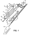
- Figure 1 shows schematically a preferred embodiment of the present invention, illustrating a diagram of the inventive process and apparatus for treating the working surface of refractory bricks before their installation in reactors.
- Figure 2 shows schematically another embodiment of the invention for treating the working surface of refractory bricks after they have been installed in a direct reduction reactor.
- Figure 3 shows an enlarged photomicrograph of the brick surface after treatment according to the invention.
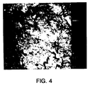
- Figure 4 shows an enlarged photomicrograph of the brick surface before treatment according to the invention.
- numeral 10 generally designates a refractory brick to be treated, having non-working surfaces 12 and a working surface 14 (i.e. the surface 14 that is exposed directly to the reactor's interior hot atmosphere).
- the working surface 14 of the brick 10 is coated with a mixture 17 of silica sand and water, preferably in a ratio of 4 parts of sand to 1 part of water by weight; said coating preferably having a thickness from 0.1 to 2 millimeters.
- Effective binders other than water could be used, but probably not as inexpensively.
- the sand utilized has preferably a grain size of up to -100 mesh, e.g. having openings of about 0.25 millimeters. The surface is then dried and any excess of sand removed, filling the voids in the brick and presenting a smooth surface.
- the surface to be treated is passed in front of a high temperature flame 16, having a temperature above 1,700°C, preferably above 2,000°C, produced for example by an oxy-acetylene burner 18 fed with standard piping for fuel and oxidant 22.
- the burner 18 is protected by a cooling sleeve 20 through which cooling water is passed in order to maintain the burner at allowable metal temperatures.
- Suitable piping 21 for cool water feeding and hot water removal are connected to said cooling sleeve 20.
- the burner nozzles are positioned at a close distance 15 (extending from their nozzle openings to the surface to be treated); so that the flame impinges directly on the sand grains and while fusing them the hot gases cause the resulting fused surface to present rounded angles as can be appreciated by reference to the Figure 3 photomicrograph.
- This distance (for an array of oxy-acetylene torch nozzles) is preferably maintained within 0.5 to 2 millimeters (depending on the flame shape, gas velocity, intensity, etc.).
- Suitable means are utilized to move the flame in relation to the surface treated, for example a moving platform 24 mounted on wheels which move on tracks 26.
- Driving means for example an endless screw 28 rotated by motor 30 moves the platform 24 back and forth by changing its direction of rotation.
- Micro switches 32 and 34 operated by the platform activate the change in direction of rotation the motor 30.
- An operator then replaces the already treated brick for an untreated brick at one or both of the ends of track 26. It is to be understood of course that the relative movement between the brick to be treated 10 and the burner 18 can be done by moving the burner instead of the brick, or using other means for causing said movement other than the platform 24.
- the translational velocity of the surface 14 relative to the flame 16 must be fast enough so that the sand grains coating said surface 16 melt down but not so slow as to permit heat transmission into the body of the brick which would cause the brick to be generally super heated and thereby develop internal stresses and other alterations in the quality characteristics of the brick.
- the gas velocity of the torch in the illustrated embodiment preferably is in the range from about 1 to about 2 cm/sec.
- the pressure of the gas flame can even be adjusted to cause a flow or smearing of the fused surface to aid in the smoothing thereof.
- the numeral 50 generally designates a direct reduction reactor of the type where a moving bed of iron ore particles, usually pellets, descend downwardly and are contacted with a reducing gas with a composition comprising principally hydrogen and carbon monoxide, plus carbon dioxide and methane, and minor amounts of other hydrocarbons and nitrogen, at a temperature in the range of about 850°C to about 1050°C.
- Such reducing gas is introduced to the reactor 50 at point 52 and is distributed through a plenum chamber 54 around the reactor so that the reducing gas enters from the periphery through nozzles 56 and is removed from the reactor through an outlet not shown located in the upper part of said reactor, in a manner already known in the art (see patents cited above).
- a conical section 58 which converges to at least one outlet, not shown, through which the already reduced ore or Direct Reduced Iron (DRI) is discharged.
- this lower zone 58 is used as a cooling zone for DRI, in order to cool it down to ambient temperature for its handling without reoxidation problems.
- a cooling gas stream is circulated countercurrently to the DRI.
- Such cooling gas is introduced at the lower part thereof, and is removed hot at the upper part thereof. Both the reducing gas and the cooling gas are recycled to the reactor.
- the cooling gas is not circulated through the lower zone 58 and is discharged hot.
- the hottest zone of the reactor 50 is that zone proximal to the entrance of the hot reducing gas, which is designated by numeral 60 and comprises about 2 meters above and below the level of the hot reducing gas nozzles 56.
- the refractory surface of this zone 60 is treated according to the invention in order to decrease the adhesion of iron ore particles to the refractory bricks.
- An oxy-acetylene flame having a temperature above 1,700°C, preferably above 2,000°C is produced in a burner 62 in known manner and is applied to the surface of the refractory bricks which will face the iron ore particles to be reduced.
- the connections of oxygen, acetylene, cooling water are not shown for simplicity of the schematic diagram.
- a scaffold 64 or a similar support is positioned inside the reactor in order to move the burner 62 relative to the reactor walls by means, for example, of a suspension system 66 (shown as a winch with a swing arm suspending burner 62 by a cable) which can be controlled by an operator so as to fuse the sand grains applied with water to the internal surface of the zone 60.
- a suspension system 66 shown as a winch with a swing arm suspending burner 62 by a cable
- Treatment of installed bricks is made in the same way as the treatment of individual bricks as illustrated in figure 1, namely: a mixture of silica sand and water is applied to the surface to be treated, said surface is then dried and the excess of sand removed and the high temperature flame is applied to said surface.
- the method is effective even on such vertical surfaces.
- Figure 4 is a photomicrograph of the surface of a refractory brick before being treated according to the invention.
- Figure 3 is a photomicrograph of the same surface after treatment.
- Figure 3 shows that certain areas have been fused and that the cracks and irregularities of the surface of the untreated brick have been greatly improved by filling, fusing, and smoothing.
- the treatment by direct heating of the silica coating to temperatures above the melting temperature of the silica sand will cause this sand to fuse and provide a smoother surface such that the iron ore particles will find less voids and peaks and in general less places suitable to physically sustain the build up of "slabs" and agglomerates on the surface of the bricks.
- the fused surface can be effective even if not uniformly smooth and even if somewhat porous. It is sufficient, if the cracks, voids, and sharp angles have been effectively filled and smoothed to reduce the adhesion and build up of aggragates and slabs in the iron ore reduction reactors in which the brick is used to the degree such that the special treatment of such surface is cost effective.
Applications Claiming Priority (2)
| Application Number | Priority Date | Filing Date | Title |
|---|---|---|---|
| US418832 | 1989-10-10 | ||
| US41883295A | 1995-04-07 | 1995-04-07 |
Publications (1)
| Publication Number | Publication Date |
|---|---|
| EP0736505A1 true EP0736505A1 (de) | 1996-10-09 |
Family
ID=23659730
Family Applications (1)
| Application Number | Title | Priority Date | Filing Date |
|---|---|---|---|
| EP96105349A Withdrawn EP0736505A1 (de) | 1995-04-07 | 1996-04-03 | Feuerfester Ziegel für Reaktoren für die Eisenerz-Reduktion |
Country Status (4)
| Country | Link |
|---|---|
| US (1) | US5766542A (de) |
| EP (1) | EP0736505A1 (de) |
| AU (1) | AU704094B2 (de) |
| ZA (1) | ZA962685B (de) |
Cited By (2)
| Publication number | Priority date | Publication date | Assignee | Title |
|---|---|---|---|---|
| ES2165779A1 (es) * | 1999-09-27 | 2002-03-16 | Refractarios Sevilla S A | Ladrillo refractario blanqueado y su procedimiento de fabricacion. |
| CN106435572A (zh) * | 2016-11-18 | 2017-02-22 | 无锡明盛纺织机械有限公司 | 一种循环流化床锅炉耐高温抗磨蚀涂层的制备方法 |
Families Citing this family (11)
| Publication number | Priority date | Publication date | Assignee | Title |
|---|---|---|---|---|
| CA2398266C (en) * | 2000-01-28 | 2009-02-03 | Pacific Edge Holdings Pty. Ltd. | Process for upgrading low rank carbonaceous material |
| US9242889B2 (en) * | 2005-11-18 | 2016-01-26 | Hoya Corporation | Method of manufacturing formed article, glass material, and method of determining shape of glass material and mold |
| EP1964819B1 (de) * | 2005-11-18 | 2017-05-10 | Hoya Corporation | Verfahren zur herstellung eines formkörpers |
| RU2416576C2 (ru) * | 2005-11-30 | 2011-04-20 | Хойа Корпорейшн | Способ производства формованного изделия, покрывающий элемент и формовочное устройство, содержащее таковой |
| JP5065662B2 (ja) * | 2005-12-15 | 2012-11-07 | 新日鉄エンジニアリング株式会社 | 高炉用保護一体カーボン質ブロックおよび高炉のカーボン質ブロックの築炉方法 |
| ITRE20060060A1 (it) * | 2006-05-15 | 2007-11-16 | Sacmi Forni Spa | Metodo per la realizzazione di piastre refrattarie, relativa piastra e forno a tunnel con dette piastre |
| JP5393664B2 (ja) * | 2008-05-30 | 2014-01-22 | Hoya株式会社 | レンズ用鋳型の製造方法 |
| EP2402132A4 (de) * | 2009-02-27 | 2014-10-15 | Hoya Corp | Vorrichtung zur herstellung einer form für eine linse und verfahren zur herstellung eines brillenglases |
| WO2010098137A1 (ja) * | 2009-02-27 | 2010-09-02 | Hoya株式会社 | レンズ用鋳型の製造方法および眼鏡レンズの製造方法 |
| CN106400008A (zh) * | 2016-11-18 | 2017-02-15 | 无锡明盛纺织机械有限公司 | 一种循环流化床锅炉耐高温抗磨蚀涂层的制备方法 |
| IT201800010817A1 (it) * | 2018-12-05 | 2020-06-05 | Danieli Off Mecc | Recipiente per contenere ferro di riduzione diretta (dri) |
Citations (9)
| Publication number | Priority date | Publication date | Assignee | Title |
|---|---|---|---|---|
| DE2105159A1 (de) * | 1970-02-13 | 1971-08-19 | United States Borax Chem | Verfahren zur Behandlung der Ober flache von Baumaterialien |
| DE2223142A1 (de) * | 1971-05-14 | 1972-11-30 | Hoeganaes Ab | Feuerfestes Auskleidungsmeterial und Auskleidungen auf der Grundlage von Siliciumdioxid,Aluminiumsilikat oder Aluminiumoxid |
| US3715228A (en) * | 1971-01-25 | 1973-02-06 | United States Borax Chem | Method for treating surfaces of building materials |
| GB1330298A (en) * | 1969-12-10 | 1973-09-12 | English Clays Lovering Pochin | Building elements |
| US4793856A (en) * | 1987-09-08 | 1988-12-27 | Hylsa, S.A. De C.V. | Process for the direct reduction of iron ores |
| EP0296981A2 (de) * | 1987-06-26 | 1988-12-28 | Vesuvius Crucible Company | Isolierbeschichtung für feuerfeste Körper, Beschichtungsverfahren und verwandte Artikel |
| DE3735444A1 (de) * | 1987-07-31 | 1989-02-16 | Stopinc Ag | Feuerfestes verschleissteil eines verschlussorganes fuer metallschmelze enthaltende behaelter |
| US5181954A (en) * | 1991-01-14 | 1993-01-26 | Hylsa S.A. De C.V. | Method for coating iron-bearing particles to be processed in a direct reduction process |
| EP0637571A2 (de) * | 1993-08-03 | 1995-02-08 | Hoechst CeramTec Aktiengesellschaft | Keramisches Bauteil mit einem korrosionsbeständigen Überzug |
Family Cites Families (13)
| Publication number | Priority date | Publication date | Assignee | Title |
|---|---|---|---|---|
| US1285244A (en) * | 1918-09-14 | 1918-11-19 | W W Lapham | Method of constructing furnaces and fire-bricks therefor. |
| US3330627A (en) * | 1963-09-09 | 1967-07-11 | Titanium Metals Corp | Corrosion resistant chlorinator lining |
| US3534946A (en) * | 1967-08-11 | 1970-10-20 | Volkswagenwerk Ag | Through-flow furnace |
| BE759927A (fr) * | 1969-12-10 | 1971-06-07 | Midland Ross Corp | Procede et appareil pour la reduction d'oxydes de fer dans une atmosphere gazeuse reductrice. |
| US3764123A (en) * | 1970-06-29 | 1973-10-09 | Midland Ross Corp | Method of and apparatus for reducing iron oxide to metallic iron |
| US3749386A (en) * | 1971-07-01 | 1973-07-31 | Midland Ross Corp | Method and means for reducing iron oxides in a gaseous reduction process |
| US4046557A (en) * | 1975-09-08 | 1977-09-06 | Midrex Corporation | Method for producing metallic iron particles |
| US4002422A (en) * | 1975-09-22 | 1977-01-11 | Midrex Corporation | Packed bed heat exchanger |
| US4375983A (en) * | 1979-04-26 | 1983-03-08 | Hylsa, S.A. | Method of making sponge metal |
| US4336063A (en) * | 1980-09-29 | 1982-06-22 | Hylsa, S.A. | Method and apparatus for the gaseous reduction of iron ore to sponge iron |
| US4428772A (en) * | 1981-12-02 | 1984-01-31 | Hylsa, S.A. | Method for reducing metal ore |
| US4556417A (en) * | 1983-05-17 | 1985-12-03 | Hylsa, S.A. | Process for the direct reduction of iron ores |
| US5078787A (en) * | 1990-06-01 | 1992-01-07 | Hylsa S.A. De C.V. | Method and apparatus for the production of hot direct reduced iron |
-
1996
- 1996-04-03 EP EP96105349A patent/EP0736505A1/de not_active Withdrawn
- 1996-04-03 ZA ZA962685A patent/ZA962685B/xx unknown
- 1996-04-09 AU AU50520/96A patent/AU704094B2/en not_active Ceased
-
1997
- 1997-04-30 US US08/848,325 patent/US5766542A/en not_active Expired - Fee Related
Patent Citations (9)
| Publication number | Priority date | Publication date | Assignee | Title |
|---|---|---|---|---|
| GB1330298A (en) * | 1969-12-10 | 1973-09-12 | English Clays Lovering Pochin | Building elements |
| DE2105159A1 (de) * | 1970-02-13 | 1971-08-19 | United States Borax Chem | Verfahren zur Behandlung der Ober flache von Baumaterialien |
| US3715228A (en) * | 1971-01-25 | 1973-02-06 | United States Borax Chem | Method for treating surfaces of building materials |
| DE2223142A1 (de) * | 1971-05-14 | 1972-11-30 | Hoeganaes Ab | Feuerfestes Auskleidungsmeterial und Auskleidungen auf der Grundlage von Siliciumdioxid,Aluminiumsilikat oder Aluminiumoxid |
| EP0296981A2 (de) * | 1987-06-26 | 1988-12-28 | Vesuvius Crucible Company | Isolierbeschichtung für feuerfeste Körper, Beschichtungsverfahren und verwandte Artikel |
| DE3735444A1 (de) * | 1987-07-31 | 1989-02-16 | Stopinc Ag | Feuerfestes verschleissteil eines verschlussorganes fuer metallschmelze enthaltende behaelter |
| US4793856A (en) * | 1987-09-08 | 1988-12-27 | Hylsa, S.A. De C.V. | Process for the direct reduction of iron ores |
| US5181954A (en) * | 1991-01-14 | 1993-01-26 | Hylsa S.A. De C.V. | Method for coating iron-bearing particles to be processed in a direct reduction process |
| EP0637571A2 (de) * | 1993-08-03 | 1995-02-08 | Hoechst CeramTec Aktiengesellschaft | Keramisches Bauteil mit einem korrosionsbeständigen Überzug |
Cited By (2)
| Publication number | Priority date | Publication date | Assignee | Title |
|---|---|---|---|---|
| ES2165779A1 (es) * | 1999-09-27 | 2002-03-16 | Refractarios Sevilla S A | Ladrillo refractario blanqueado y su procedimiento de fabricacion. |
| CN106435572A (zh) * | 2016-11-18 | 2017-02-22 | 无锡明盛纺织机械有限公司 | 一种循环流化床锅炉耐高温抗磨蚀涂层的制备方法 |
Also Published As
| Publication number | Publication date |
|---|---|
| ZA962685B (en) | 1996-07-25 |
| AU5052096A (en) | 1996-10-17 |
| AU704094B2 (en) | 1999-04-15 |
| US5766542A (en) | 1998-06-16 |
Similar Documents
| Publication | Publication Date | Title |
|---|---|---|
| US5766542A (en) | Refractory bricks for iron ore reduction reactors | |
| AU760611B2 (en) | Iron production method of operation in a rotary hearth furnace and improved furnace apparatus | |
| AU765530B2 (en) | Method of producing a reduced metal, and traveling hearth furnace for producing same | |
| CA2071370C (en) | Process and mixture for forming a coherent refractory mass on a surface | |
| US6749664B1 (en) | Furnace hearth for improved molten iron production and method of operation | |
| US4946806A (en) | Flame spraying method and composition | |
| JP2002097508A (ja) | 還元鉄製造方法および還元鉄製造装置 | |
| WO1999016914A1 (fr) | Four a sole mobile et son procede de fonctionnement | |
| US3900696A (en) | Charging an electric furnace | |
| CA1170838A (en) | Process for treating metallic starting materials for smelting plants, particularly iron sponge particles | |
| JP3086705B2 (ja) | セラミック物品を製造するための方法及び装置 | |
| KR20110054079A (ko) | 용광로에서의 철 생산율 증가방법 | |
| CA1142739A (en) | Process for coating the inner wall of a furnace or like apparatus | |
| JPS61253309A (ja) | 竪型炉を用いる直接製鉄方法 | |
| SU1716281A1 (ru) | Способ упрочнени футеровки вращающейс печи | |
| JP5055794B2 (ja) | 還元金属の製造方法 | |
| JP3451901B2 (ja) | 移動型炉床炉の操業方法 | |
| SU870465A1 (ru) | Способ термообработки железорудных окатышей | |
| JPS5917347B2 (ja) | 回転還元炉 | |
| JPS5942229B2 (ja) | 耐火物ライニングの火炎溶射補修層の強化方法 | |
| JPH1161217A (ja) | 還元鉄製造方法および装置 | |
| SU1138630A1 (ru) | Способ упрочнени футеровки вращающейс печи | |
| MXPA01004771A (en) | Iron production method of operation in a rotary hearth furnace and improved furnace apparatus | |
| SU954434A1 (ru) | Способ выплавки стали в дуговой электропечи | |
| Ghosh et al. | Gunniting—A Recent Technique |
Legal Events
| Date | Code | Title | Description |
|---|---|---|---|
| PUAI | Public reference made under article 153(3) epc to a published international application that has entered the european phase |
Free format text: ORIGINAL CODE: 0009012 |
|
| AK | Designated contracting states |
Kind code of ref document: A1 Designated state(s): DE GB |
|
| RIN1 | Information on inventor provided before grant (corrected) |
Inventor name: HERNANDES-OTERO, TOMAS GILBERTO Inventor name: FLORES-VERDUGO, MARCO AURELIO Inventor name: BERRUN-CASTANON, JORGE DOMINGO |
|
| 17P | Request for examination filed |
Effective date: 19970409 |
|
| 17Q | First examination report despatched |
Effective date: 19970624 |
|
| STAA | Information on the status of an ep patent application or granted ep patent |
Free format text: STATUS: THE APPLICATION IS DEEMED TO BE WITHDRAWN |
|
| 18D | Application deemed to be withdrawn |
Effective date: 19990716 |