EP0736282B1 - Dispositif de contrôle d'une soupape d'un appareil de cuisson sous pression - Google Patents
Dispositif de contrôle d'une soupape d'un appareil de cuisson sous pression Download PDFInfo
- Publication number
- EP0736282B1 EP0736282B1 EP96104703A EP96104703A EP0736282B1 EP 0736282 B1 EP0736282 B1 EP 0736282B1 EP 96104703 A EP96104703 A EP 96104703A EP 96104703 A EP96104703 A EP 96104703A EP 0736282 B1 EP0736282 B1 EP 0736282B1
- Authority
- EP
- European Patent Office
- Prior art keywords
- lid
- pressure cooker
- slider
- engaging
- cooker according
- Prior art date
- Legal status (The legal status is an assumption and is not a legal conclusion. Google has not performed a legal analysis and makes no representation as to the accuracy of the status listed.)
- Expired - Lifetime
Links
Images


Classifications
-
- A—HUMAN NECESSITIES
- A47—FURNITURE; DOMESTIC ARTICLES OR APPLIANCES; COFFEE MILLS; SPICE MILLS; SUCTION CLEANERS IN GENERAL
- A47J—KITCHEN EQUIPMENT; COFFEE MILLS; SPICE MILLS; APPARATUS FOR MAKING BEVERAGES
- A47J27/00—Cooking-vessels
- A47J27/08—Pressure-cookers; Lids or locking devices specially adapted therefor
- A47J27/09—Safety devices
Definitions
- the present invention relates to a pressure cooker comprising a device for controlling the working valve.
- Traditional pressure cookers generally comprise a container, whereon a closure lid is mounted, with the edge of the latter and the edge of the container which both have respective jutting projections, suitable for engaging reciprocally one with the other and for locking the lid on the container, following relative rotation between the lid and the container, and each comprising at least one respective handle, these two handles being mobile between an opening position of the lid, wherein they are angularly distanced, and a closure position wherein they are on top of each other.
- the lid of the cooker has an aperture at which a working valve is attached for releasing the steam produced by cooking, when the internal pressure has reached a predetermined level. Said working valve has a shutter for closing said aperture.
- the working valve In traditional cookers the working valve, generally of the gravity type, is usually arranged in a substantially central position of the lid, so that, when cooking has ended and the cooker has to be opened by manually acting on said valve to release the pressure inside the cooker, the user of the cooker risks burning his or her hand with the pressurised steam which is released from the cooker or by accidentally touching the boiling lid.
- Gravity valves for pressure cookers are likewise known which are suitable for allowing cooking at two different levels of pressure.
- the gravity element of the valve is simply replaced by another element of different weight according to cooking needs.
- Other types of valve have a lever for controlling the pressure setting which is located directly on the working valve arranged virtually in the centre of the lid.
- the user goes to actuate the valve to change the cooking pressure, he or she runs the risk of being burnt due to inopportune contact with the hot lid or due to reverberations of heat from the flames of the gas ring at the side of the cooker.
- Some types of pressure cookers currently in use have the handle of the lid which engages with the handle of the container, via a suitable rotation locking and engaging part, so as to lock, following a rotation, the lid on the container. They also have a passage in the lid through which a safety pin, for locking opening of the cooker, slides, which pin, when it rises through the effect of the pressure in the cooker, engages directly with the handle of the lid, preventing its relative rotation in relation to the handle of the cooker container, thus preventing opening of the cooker if the pressure inside the latter is still above a predetermined safety level.
- some pressure cookers of a known type have, on the handle attached to the lid, a pushbutton which controls the mechanism for engaging and locking of the relative rotation of the handles.
- Said control pushbutton in order to allow disengaging of the handles and opening of the pressure cooker, moves in a radial direction and is pushed by a preloaded spring into a backward position of locking the opening.
- the pushbutton In order to open the cooker the pushbutton has to be pressed hard with a finger, so as to push it towards the centre of the lid, while the rest of the hand is used to grasp the upper handle. At the same time the other hand is used to grasp the underlying handle and attempts are made to rotate the two handles one in relation to the other.
- the object of the present invention is that of providing a device for controlling a working valve of a pressure cooker such as to avoid the disadvantages shown by similar devices hitherto known, in particular of providing a mechanism for controlling the working valve whereby any risk of burning for the user of the cooker is avoided.
- Another object of the present invention is that of providing in a pressure cooker a centralised mechanism for controlling opening of the cooker and of the working valve. Yet another object is that of providing a centralised system for controlling opening of the working valve such that no opening of the cooker is possible if the cooker contains pressurised, overheated steam.
- the first object is achieved by providing a device for controlling the working valve of a pressure cooker which, according to the disclosure in the characterising part of claim 1, comprises, at said handle of the lid, a control pushbutton which is angularly mobile and which can be selectively positioned in predetermined angular positions of actuation, and, below the shutter of the valve, a cylindrical body, having a longitudinal axis, attached to said lid in order to rotate around said longitudinal axis and integral with said pushbutton to rotate with the latter, and a raising slider for said shutter of the valve, also cylindrical, coaxial and facing said cylindrical body, said raising slider being integral with said lid so as to be mobile axially in the direction of said longitudinal axis and cam means provided between said slider and said cylindrical body for driving the axial movement of said slider for raising the shutter following a rotation of said control pushbutton.
- the pushbutton is made to rotate and is positioned in the required angular position of working of the system and all the fingers of the hands can be used to act on the handles to open the cooker.
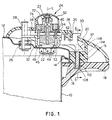
- the pressure cooker comprises in a traditional manner a container 10 whereon a lid 12 for closing the container 10 is mounted, whose respective edges both have respective jutting projections 14, 16 suitable for mutually engaging one with the other and for locking the lid 12 on the container 10 following a relative rotation between the lid 12 and the container 10.
- said container 10 and said lid 12 each have respective handles 18, 18' and 20, 20', of which handles 18 and 20 are intended to engage one with the other, by means of a suitable part for engaging and locking rotation 15, and to lock, following a rotation, the lid 12 onto the container 10.
- handles 20, 20' of the lid are mobile with the latter between a position of opening of the cooker, shown by a dotted line in Figure 2, wherein they are angularly distanced in relation to the handles 18, 18' of the cooker, and a position of closure shown by an unbroken line in said Figure 2, wherein they are arranged above said handles 18, 18' of the cooker.
- the lid of the cooker 12 also comprises an aperture 22 at which a working valve 24 is attached for releasing the steam produced by cooking, having a shutter 23 for closing said aperture 22, and a passage 26 wherein a safety pin 28 slides to lock opening of the cooker, suitable for preventing opening of the lid 12 when the internal pressure is still above a predetermined safety pressure.
- the device for actuating the valve of the pressure cooker comprises a control lever 30 angularly mobile and selectively positionable in predetermined angular positions of actuation, a cylindrical body 32 with a longitudinal axis L, attached rotatably to said lid 12 so as to rotate around said longitudinal axis and integral with said lever 30 to rotate with the latter, a slider 34 for raising said shutter 23 of the valve 24, also cylindrical, concentric and inside said cylindrical body 32.
- Said raising slider 34 is integral with said lid 12 so as to be mobile in the sole direction of said longitudinal axis L.
- suitable cam means are provided between said slider 34 and said cylindrical body 32, for driving the axial movement of said slider 34 following a rotation of said cylindrical body 32.
- said control lever 30 projects from the handle 20 of the lid 12 through an arched slit of the latter denoted by reference numeral 35 at which suitable reference indications marked by the letters "A” and “S” and by the numbers “1” and “2” are provided on the handle 20 to distinguish different ways of operating of the system and whose meaning will be further explained hereinbelow.
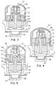
- said actuation body 32 is in the form of a hollow cylinder which has a radial arm 36 wherefrom said control lever 30 with a general "L" shape projects above and a block 37 for actuating said part for engaging and locking 15 together the handles 18, 20 projects below.
- a finger 38 projects radially and is angularly displaced in relation to the radial path described by said arm 36. Said finger 38, as shown in Figures 1 and 8, interferes during the movement of rotation of said cylindrical body 32 with the axial sliding path of said safety pin 28.
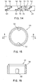
- a cylindrical stem 40 is provided, wherefrom a vent 42 extends above and wherein a central longitudinal hole 44 is formed, open at both ends.
- Said stem 40 is, in a traditional manner, firmly attached to said lid 12 by means of a perforated nut 45 which is screwed to the lower threaded portion 48 of said stem 40 projecting below the lid 12 through said aperture 22.
- said stem 40 defines a pivoting element for said actuation body 32 and also has on the two opposite sides of its external surface two vertical grooves 46 suitable for guiding the vertical movement of said slider 34.
- FIGS 10 and 11 also show that said cylindrical actuation body 32 has below an annular flange 49 for supporting said slider 34 and provided with holes 51 for the percolation of the condensate and of the cooking steam residues released from the working valve 24.
- Said flange 49 is longitudinally restrained by the annular shoulder 55 of the stem 40 whereon it rotates by means of its internal edge 49'.
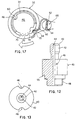
- Said slider 34 which is shown in greater detail in Figures 14 to 16, is in the form of a short, hollow and cylindrical element which has on its internal surface vertical ribs 50 which are suitable for insertion in the grooves 46 of said block 40, so that each rotation of the slider 34 is prevented but its free sliding along the longitudinal axis L is permitted.
- said slider 34 is placed coaxially to the interior of said actuation body 32 and has on its external lateral surface, as shown in Figure 14, three sliding grooves 52 in which three pintles 53 (shown in Figure 10) are inserted which extend radially from the lateral internal surface of said cylindrical body 32. Said grooves 52 and said pintles 53 define said cam means, allowing driving, following a rotation of said actuation body 32, of the axial movement of the slider 34.
- said pintles 53 are angularly distanced one from the other by 120°, while said sliding grooves 52 each have a first short horizontal section 54 situated at the lower edge of said slider 34 wherefrom an oblique section 56 for driving raising of said slider 34 extends.
- the cylindrical slider 34 also has an upper tapered edge 58 for engaging and raising said shutter of the valve.
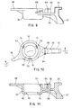
- Said means for stopping rotation of said lever 30 comprise, as shown in Figure 17, a flexible element 60 in the form of a shaped metal wire which has an end 62 for insertion in a vertical slot 64 formed in a protuberance 66 which extends upwards from said arm 36 of said actuation body and is arranged between said lever 30 and said cylindrical actuation body 32, as is shown more clearly also in the previously described Figures 9 to 11.
- said vertical grooves 70 which define sort of positioning notches, have a different height one from the other due to the fact that the slider 34 has in the various angular working positions a different height position.
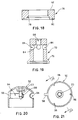
- first cylindrical extra weight 72 integral with the shutter 23 of said working valve 24 is a first cylindrical extra weight 72, shown more clearly in Figure 19, while a second extra weight 74, in the form of an annular element coaxial and external to said first extra weight 72 in respect whereof it is axially sliding and resting on the latter by means of respective and opposite annular and conical engaging bands 76 and 78 respectively, is shown in Figure 18.
- said second annular extra weight 74 also has an annular housing 80 for engaging the upper edge 58 of said raising slider 34.
- the reference numeral 82 denotes the edge or upper annular face of said second annular weighting element 74, suitable for engaging portions of the external casing of the valve for raising the latter and the total opening of the valve itself, as will be explained further hereinunder.
- said first extra weight 72 has a series of radial holes 84 angularly distanced for the release of the steam, as well as a threaded hole 88 wherein the shutter 23 is screwed and which has correspondingly, as shown in Figure 20, external attachment threading 90.
- Said external protection casing 92 has horizontal slits 94 for the release of the steam and internally a series of fins or radial projections, more particularly three fins which are angularly distanced one from the other at 120°, denoted by reference numeral 96, whose lower edge can be engaged by the upper annular face or edge 82 of said second annular extra weight 74, when the latter is raised by the slider 34.
- the external extra weight 74 is also raised, which in turn raises the casing 92 and the shutter 23 of the working valve integral therewith, so as to allow complete release of the steam from inside the cooker.
- Said casing 92 also has an external fin 98 which extends radially and engages in a suitable housing 100 provided in the handle 20 of the lid, as shown in Figure 2, to prevent any undesirable rotation of said casing 92, and thus prevent one of the slits 94 from positioning turned towards the lever 30 and the release of steam through the latter from causing heating of said pushbutton and the risk of burning of the user.
- said handle 20 attached to the upper lid has a convex upper surface wherein a substantially circular hole 102 is formed in an approximately central position to house said working valve 24 and having a kind of serration defining said housing 100 for the fin 98 of the casing 92, and at the sides of the latter a smaller circular hole 104 for the passage of said safety pin 28 and an arched slit 106 for the passage of said control lever 30 respectively.
- Said engaging and locking part 15, as can be understood better by referring also to Figure 23, is in the form of a shaped plate having a tooth 108 which is inserted in a housing 110 of the handle 18 attached to the container of the cooker, shown in Figure 24, achieving locking of the handles of the cooker.
- Said engaging and locking part 15 has a hole 112 wherein, as shown in Figures 6 and 7, a pin 114 is inserted and which allows it to be pivoted to said handle 20 attached to the upper lid 12 and is also subjected to the action of a return spring 116 in a preloaded condition to maintain said tooth 108 of the engaging and locking part 15 inserted in the housing 110 of the lower handle 18 and maintain the lid 12 locked on the container 10.
- said engaging and locking part 15 has a trigger 118 whereon, following a rotation of the lever 30 and of the actuation body 32 integral therewith, the block 37 of said actuation body engages to remove said tooth 108 from the housing 110 and allow disengaging between the handles and opening of the cooker.
- the operation of the system provides, in short, four working conditions corresponding to four diferent angular working positions for the lever 30 distinguished on the handle 20 of the lid by the aforementioned references A, S, 1 and 2 which mean, respectively, the letter A, a condition of opening of the lid, the letter S, a condition of total release of steam from inside the cooker, the reference numeral 1, a first condition of cooking at a predetermined pressure for example 0.5 bar, and finally the reference numeral 2, a second condition of cooking for foods which require more intensive treatment wherein cooking takes place at a higher predetermined pressure than the previous one, for example 1 bar.
Landscapes
- Engineering & Computer Science (AREA)
- Food Science & Technology (AREA)
- Cookers (AREA)
- General Preparation And Processing Of Foods (AREA)
Claims (17)
- Autocuiseur du type comprénant un récipient (10), sur lequel est monté un couvercle (12) pour la fermeture du récipient, le bord du couvercle et le bord du récipient (10) tous les deux ayants des ressauts qui se chevauchent (14,16) de façon qu'ils s'engagent réciproquement l'un avec l'autre et bloquent le couvercle (12) sur le récipient (10), à la suite d'une rotation relative entre le couvercle (12) et le récipient (10), tous les deux comprennent au moins une poignée (18,20), les poignées susdites (18,20) étant mobiles entre une position d'ouverture du couvercle (12) , où elles sont espacées en angle , et une position de fermeture, où elles sont placées l'une au dessus de l'autre; le couvercle (12) comprenant une ouverture (22) où est attachée une soupape de surcharge (24) pour la discharge de la vapeur produisée par la cuisson, la soupape susdite (24) ayant un obturateur (23) qui ferme l'ouverture susdite (22); caractérisée par le fait qu'il comprend , à la poignée susdite (20) du couvercle (12), un levier de contrôle (30) qui est mobile en angle et qui peut être positionné sélectivement dans des positions angulaires prédéterminées de commande, au dessous de cet obturateur (23) de la soupape (24) un corps cylindrique (32) , ayant un axe longitudinal , fixé au susdit couvercle (12) de façon qu'il peut tourner autour de cet axe longitudinal et integral avec dit levier (30) pour tourner avec le dernier, un curseur de soulevement (34) pour l'obturateur (23) de la soupape (24), de plus cylindrique, coaxial et situé devant le corps cylindrique (32) , le courseur de soulevement (34) étant fixé pivotant par rapport au couvercle (12) , ainsi qu'il est mobile en sens axial dans la direction de l'axe longitudinal, et moyens de came entre le courseur de soulevement (34) et le corps cylindrique (32) qui permet le mouvement axial du courseur (34) pour soulever l'obturateur (23) à la suite d' une rotation du levier de contrôle (30).
- L'autocuisuer selon la revendication 1, où les poignées (18,20) de l'autocuiseur sont projetées pour s'engager l'une avec l'autre, au moyen d'une pièce destinée à la rotation (15) pour l'engagement et la fermeture et à la fermeture, suivante une rotation, du couvercle (12) sur le récipient (10); caractérisé par le fait qu'il comprend un bloc intégré avec le corps de contrôle (32), à la suite de la rotation du levier (30), de la pièce (15) pour engager et fermer ensemble les poignées (18,20), de façon d'engager et dégager respectivement , les poignées susdites (18,20) l'une par rapport à l'autre.
- L'autocuiseur selon la revendication 1 ou 2, où le couvercle (12) de l'autocuiseur comprend un passage (26) où glisse une cheville de sécurité (28) pour la bloquer l'ouverture de l'autocuiseur, projetée pour prévenir l'ouverture du couvercle (12) lorsque la pression intérieure est supérieure à une pression de sécurité prédéterminée; caractérisé par le fait qu'il comprend un cliquet (38) qui sort radiale du corps cylindrique (32), ce cliquet s'interposant pendant le mouvement de rotation du corps cylindrique (32) suivant la rotation du levier de contrôle (30) avec le parcours dé glissement axial de la cheville de sécurité (28) .
- L'autocuiseur selon n'importe quelle revendication précédente, caractérisé par le fait que l'obturateur (23) de la soupape (24) pour la fermeture de l'ouverture (22) est intégré avec un premier poids extra cylindrique (72), où un deuxième poids extra annulaire peut s'appuyer (74), coaxial et extérieur au premier poids extra cylindrique (72), et mobile axialement par rapport au deuxième poids extra annulaire extérieur (74), ayant une surface inferieure pour l'engagement du courseur de soulevement (34).
- L'autocuiseur selon la revendication 4, où la soupape (24) comprend une capsule protective extérieure (92) ayante fentes (94) pour l'échappement de la vapeur , à laquelle est rattaché l'obturateur (23),caractérisé par le fait que la capsule susdite (92) a à l'intérieur au moins un ressaut radial (96) pour engager et soulever le poids extra annulaire extérieur (74) par un bord supérieur (82).
- L'autocuiseur selon la revendication 4, caractérisé par le courseur (34) qui présente un bord supérieur conique ou bien pointu (58) destiné à s'engager dans une gorge annulaire (80), pourvue dans la surface inferieure du dit deuxième poids extra (74).
- L'autocuiseur selon la revendication 1, caractérisé par ces moyens de came qui comprenent au moins une première, une deuxième et une troisième cheville (53) espacées à 120° l'une de l'autre et qui sortent radiales du corps cylindrique (32) et sont insérées en correspondents gorges de glissenent (52) en substance hélicoidale, pourvues sur la surface laterale du courseur (34) situé devant le corps cylindrique (32), et de bandes verticales (50) pour prévenir les mouvements longitudinals et la rotation prévus sur le courseur (34), aptes à s'insérer dans correspondents gorges verticales (46) intégrals avec le couvercle (12).
- L'autocuiseur selon la revendication 7, caractérisé par le fait que les gorges de glissement substantiellement hélicoidales (52) ont chacune une petite section horizontale initial (54), située au bord inférieur du courseur (34), d'où s'étend une section oblique (56) pour le contrôle du soulèvement du courseur (34).
- L'autocuiseur selon la revendication 1, caractérisé par le fait qu'il comprend moyens pour arrêter la rotation du levier (30) dans des positions angulaires prédéterminées.
- L'autocuiseur selon la revendication 9, caractérisé par le fait que les moyens pour arrêter la rotation du levier (30) comprennent un élément flexible (62) ayant une extrémité (84) intégrée avec le levier susdit (30) et avec le corps cylindrique (32) , et une pièce (68) pour l'insertion dans les gorges verticales (70) espacées en angle l'une de l'autre et situées sur la face extérieure du courseur (34).
- L'autocuiseur selon la revendication 7, caractérisé par le fait que, à l'ouverture de passage (22), coaxiale et concentrique avec le corps cylindrique (32) et le courseur (34), on a prévu un arbre cylindrique (40) où il y a un trou central longitudinal ( 44) , ouvert aux deux bouts, cet arbre (40) etant fermement fixé au couvercle (12), constituant un élément oscillant pour le corps (32) et ayant sur sa surface extérieure dites gorges verticales (46) où sont librement insérés les bandes verticales (50) du courseur (34), glissentes en direction axiale.
- L'autocuiseur selon la revendication 2, caractérisé par le fait que dite pièce pour engager et fermer (15) est en forme de tôle profilée, ayante un déclencheur (118) pour un dent (108) à engager la poignée (18) fixée au récipient (10), dite pièce pour engager et fermer (15) etant pivotée à la poignée (20) fixée sur le couvercle (12) et etant sujette à l'action d'un moyen élastique préchargé (116) pour soutenir soutient la pièce susdite (15) pour engager et fermer les poignées ensemble dans une condition de engagement.
- L'autocuiseur selon la revendication 1, caractérisé par le fait que le corps cylindrique (32) a en bas une bride annulaire (49) pour le courseur (34), pourvue de trous pour la percolation de l'eau de condensation et des résidus de la vapeur de cuisson échappés de la soupape (24).
- L'autocuiseur selon la revendication 5, caractérisé par le fait que la capsule (92) a une ailette extérieure (98) qui sort radiale et s'engage dans un'enveloppe correspondante (100) dans la poignée (20) pour prévenir la rotation de la capsule (92).
- L'autocuiseur selon la revendication 1, caractérisé par le fait que la poignée fixée au couvercle (20), a une surface convexe où un trou substantiellement circulaire (102) a été dessiné pour accueillir la soupape (24) ayant un sorte de dent definant dite enveloppe (100) pour l'ailette extérieure (98) de la capsule (92) pour le passage de la cheville de sécureté (28), et une fente arquée (106) puor le passage du levier de contrôle (309).
- L'autocuiseur selon la revendication 15, caractérisé par la poignée (20), qui, à la fente arquée (106) pour le passage du levier de contrôle (30), a une série d'indications de référence pour définir les positions de travail du systhème.
- L'autocuiseur selon la revendication 12, caractérisé par la poignée fixée au récipient (18) qui a un'enveloppe (110) pour l'insertion du dent (108) de la pièce (15) pour engager et fermer les poignées (18,20) ensemble.
Applications Claiming Priority (2)
| Application Number | Priority Date | Filing Date | Title |
|---|---|---|---|
| ITMI950700 | 1995-04-06 | ||
| IT95MI000700A IT1275723B1 (it) | 1995-04-06 | 1995-04-06 | Dispositivo di comando della valvola di lavoro di una pentola a pressione |
Publications (2)
| Publication Number | Publication Date |
|---|---|
| EP0736282A1 EP0736282A1 (fr) | 1996-10-09 |
| EP0736282B1 true EP0736282B1 (fr) | 2000-06-07 |
Family
ID=11371232
Family Applications (1)
| Application Number | Title | Priority Date | Filing Date |
|---|---|---|---|
| EP96104703A Expired - Lifetime EP0736282B1 (fr) | 1995-04-06 | 1996-03-25 | Dispositif de contrôle d'une soupape d'un appareil de cuisson sous pression |
Country Status (3)
| Country | Link |
|---|---|
| EP (1) | EP0736282B1 (fr) |
| DE (1) | DE69608732T2 (fr) |
| IT (1) | IT1275723B1 (fr) |
Cited By (1)
| Publication number | Priority date | Publication date | Assignee | Title |
|---|---|---|---|---|
| CN101209179B (zh) * | 2006-12-28 | 2013-04-17 | Seb公司 | 结构改进的压力蒸煮器具及相应的制造方法 |
Families Citing this family (7)
| Publication number | Priority date | Publication date | Assignee | Title |
|---|---|---|---|---|
| PT102076B (pt) * | 1997-11-07 | 2003-11-28 | Cruzinox Ind Metalurgica Lda | Dispositivo de seguranca na abertura e fecho para um recipiente de cozedura sob pressao |
| DE19822905A1 (de) * | 1998-05-22 | 1999-11-25 | Baumgarten Heinrich Kg | Dampfdruckkochtopf mit einem Sicherheitsventil |
| FR2783686B1 (fr) | 1998-09-28 | 2000-11-17 | Seb Sa | Dispositif de securite a l'ouverture d'un appareil de cuisson sous pression a fermeture a baionnettes |
| ES1041853Y (es) * | 1998-12-07 | 2000-01-01 | Fagor S Coop | Olla expres con seguridad contra el giro de la tapa. |
| IT246614Y1 (it) * | 1999-03-29 | 2002-04-09 | Lagostina Spa | Dispositivo automatico di sicurezza per una pentola a pressione |
| ES1056370Y (es) * | 2003-12-15 | 2004-07-01 | Fagor S Coop | Valvula de regulacion en una olla a presion. |
| ES2689253B2 (es) * | 2017-05-09 | 2019-04-11 | Isogona S L | Olla a presion |
Family Cites Families (6)
| Publication number | Priority date | Publication date | Assignee | Title |
|---|---|---|---|---|
| ES290269Y (es) * | 1985-11-12 | 1988-11-01 | Radar,S.Coop. | Olla a presion con cierre de bayoneta y valvula de pesa |
| ES1011685Y (es) * | 1989-10-16 | 1990-11-16 | Fagor, S. Coop. Ltda. | Olla a presion perfeccionada. |
| DE4022004C2 (de) * | 1990-07-11 | 1994-09-01 | Fissler Gmbh | Dampfdruckkochtopf |
| DE4026166A1 (de) * | 1990-08-17 | 1992-02-20 | Amc Int Alfa Metalcraft Corp | Kochgefaess |
| DE4040489A1 (de) * | 1990-12-18 | 1992-07-16 | Silit Werke | Deckel fuer kochtoepfe mit umgelegtem rand |
| FR2700825B1 (fr) * | 1993-01-28 | 1995-04-14 | Seb Sa | Dispositif de commande automatique d'une soupape à limitation de flux. |
-
1995
- 1995-04-06 IT IT95MI000700A patent/IT1275723B1/it active IP Right Grant
-
1996
- 1996-03-25 EP EP96104703A patent/EP0736282B1/fr not_active Expired - Lifetime
- 1996-03-25 DE DE69608732T patent/DE69608732T2/de not_active Expired - Lifetime
Cited By (1)
| Publication number | Priority date | Publication date | Assignee | Title |
|---|---|---|---|---|
| CN101209179B (zh) * | 2006-12-28 | 2013-04-17 | Seb公司 | 结构改进的压力蒸煮器具及相应的制造方法 |
Also Published As
| Publication number | Publication date |
|---|---|
| EP0736282A1 (fr) | 1996-10-09 |
| DE69608732D1 (de) | 2000-07-13 |
| ITMI950700A1 (it) | 1996-10-06 |
| IT1275723B1 (it) | 1997-10-17 |
| ITMI950700A0 (it) | 1995-04-06 |
| DE69608732T2 (de) | 2001-02-22 |
Similar Documents
| Publication | Publication Date | Title |
|---|---|---|
| US11992145B2 (en) | Cooking appliance for cooking food with or without pressure | |
| US12089768B2 (en) | Electric cooking appliance provided with a removable heating device | |
| US20140013960A1 (en) | Cooking Utensil for Cooking Food Under Pressure that has an Improved Control Device | |
| US6394081B1 (en) | Safety knob for domestic gas apparatuses | |
| KR101083981B1 (ko) | 압력 조리기 리드 | |
| US6648162B1 (en) | Button actuated pressure release and locking device for pressure cookers | |
| EP0736282B1 (fr) | Dispositif de contrôle d'une soupape d'un appareil de cuisson sous pression | |
| US6523459B1 (en) | Safety device for opening a pressure cooker with lug-bayonet type closure | |
| EP0972478A2 (fr) | Dispositif d'évacuation de la vapeur pour ustensiles de cuisine | |
| CZ280338B6 (cs) | Varná nádoba | |
| JPS624125B2 (fr) | ||
| EP0916298B1 (fr) | Dispositif de sécurité pour fermer ou ouvrir un appareil de cuisson sous pression | |
| WO2007140547A1 (fr) | Presse et grille de cuisson | |
| US6375150B1 (en) | Knob for gas apparatus with safety button | |
| US10051996B2 (en) | Toaster oven control knob and method of controlling a toaster oven | |
| US5154511A (en) | Trouble-light with rotatable shield | |
| CA2648899A1 (fr) | Appareil de cuisson sous pression a tarage reglable et decompression maitrisee | |
| CA2311568A1 (fr) | Appareil de cuisson | |
| EP1582122A1 (fr) | Dispositif de securité pour autocuiseur | |
| KR100406347B1 (ko) | 압력솥뚜껑 안전개폐장치 | |
| JP3277134B2 (ja) | 加熱調理器の感温センサー | |
| JPH02271811A (ja) | 圧力鍋 | |
| RU2810044C1 (ru) | Кухонный прибор для варки пищевых продуктов под давлением или без давления | |
| KR100279189B1 (ko) | 전기압력솥의 안전장치 | |
| KR0126566Y1 (ko) | 전기압력밥솥의 뚜껑개폐 안전장치 |
Legal Events
| Date | Code | Title | Description |
|---|---|---|---|
| PUAI | Public reference made under article 153(3) epc to a published international application that has entered the european phase |
Free format text: ORIGINAL CODE: 0009012 |
|
| AK | Designated contracting states |
Kind code of ref document: A1 Designated state(s): BE DE FR IT |
|
| 17P | Request for examination filed |
Effective date: 19970327 |
|
| GRAG | Despatch of communication of intention to grant |
Free format text: ORIGINAL CODE: EPIDOS AGRA |
|
| 17Q | First examination report despatched |
Effective date: 19990318 |
|
| GRAG | Despatch of communication of intention to grant |
Free format text: ORIGINAL CODE: EPIDOS AGRA |
|
| GRAH | Despatch of communication of intention to grant a patent |
Free format text: ORIGINAL CODE: EPIDOS IGRA |
|
| GRAH | Despatch of communication of intention to grant a patent |
Free format text: ORIGINAL CODE: EPIDOS IGRA |
|
| GRAA | (expected) grant |
Free format text: ORIGINAL CODE: 0009210 |
|
| AK | Designated contracting states |
Kind code of ref document: B1 Designated state(s): BE DE FR IT |
|
| REF | Corresponds to: |
Ref document number: 69608732 Country of ref document: DE Date of ref document: 20000713 |
|
| ITF | It: translation for a ep patent filed | ||
| ET | Fr: translation filed | ||
| PLBE | No opposition filed within time limit |
Free format text: ORIGINAL CODE: 0009261 |
|
| STAA | Information on the status of an ep patent application or granted ep patent |
Free format text: STATUS: NO OPPOSITION FILED WITHIN TIME LIMIT |
|
| 26N | No opposition filed | ||
| PGFP | Annual fee paid to national office [announced via postgrant information from national office to epo] |
Ref country code: BE Payment date: 20070316 Year of fee payment: 12 |
|
| PGFP | Annual fee paid to national office [announced via postgrant information from national office to epo] |
Ref country code: IT Payment date: 20080327 Year of fee payment: 13 |
|
| BERE | Be: lapsed |
Owner name: *LAGOSTINA S.P.A. Effective date: 20080331 |
|
| PGFP | Annual fee paid to national office [announced via postgrant information from national office to epo] |
Ref country code: FR Payment date: 20080331 Year of fee payment: 13 |
|
| PG25 | Lapsed in a contracting state [announced via postgrant information from national office to epo] |
Ref country code: BE Free format text: LAPSE BECAUSE OF NON-PAYMENT OF DUE FEES Effective date: 20080331 |
|
| REG | Reference to a national code |
Ref country code: FR Ref legal event code: ST Effective date: 20091130 |
|
| PG25 | Lapsed in a contracting state [announced via postgrant information from national office to epo] |
Ref country code: FR Free format text: LAPSE BECAUSE OF NON-PAYMENT OF DUE FEES Effective date: 20091123 |
|
| PGFP | Annual fee paid to national office [announced via postgrant information from national office to epo] |
Ref country code: DE Payment date: 20100330 Year of fee payment: 15 |
|
| PG25 | Lapsed in a contracting state [announced via postgrant information from national office to epo] |
Ref country code: IT Free format text: LAPSE BECAUSE OF NON-PAYMENT OF DUE FEES Effective date: 20090325 |
|
| PG25 | Lapsed in a contracting state [announced via postgrant information from national office to epo] |
Ref country code: DE Free format text: LAPSE BECAUSE OF NON-PAYMENT OF DUE FEES Effective date: 20111001 |
|
| REG | Reference to a national code |
Ref country code: DE Ref legal event code: R119 Ref document number: 69608732 Country of ref document: DE Effective date: 20111001 |