EP0736282B1 - Device controlling the working valve of a pressure cooker - Google Patents
Device controlling the working valve of a pressure cooker Download PDFInfo
- Publication number
- EP0736282B1 EP0736282B1 EP96104703A EP96104703A EP0736282B1 EP 0736282 B1 EP0736282 B1 EP 0736282B1 EP 96104703 A EP96104703 A EP 96104703A EP 96104703 A EP96104703 A EP 96104703A EP 0736282 B1 EP0736282 B1 EP 0736282B1
- Authority
- EP
- European Patent Office
- Prior art keywords
- lid
- pressure cooker
- slider
- engaging
- cooker according
- Prior art date
- Legal status (The legal status is an assumption and is not a legal conclusion. Google has not performed a legal analysis and makes no representation as to the accuracy of the status listed.)
- Expired - Lifetime
Links
Images


Classifications
-
- A—HUMAN NECESSITIES
- A47—FURNITURE; DOMESTIC ARTICLES OR APPLIANCES; COFFEE MILLS; SPICE MILLS; SUCTION CLEANERS IN GENERAL
- A47J—KITCHEN EQUIPMENT; COFFEE MILLS; SPICE MILLS; APPARATUS FOR MAKING BEVERAGES
- A47J27/00—Cooking-vessels
- A47J27/08—Pressure-cookers; Lids or locking devices specially adapted therefor
- A47J27/09—Safety devices
Definitions
- the present invention relates to a pressure cooker comprising a device for controlling the working valve.
- Traditional pressure cookers generally comprise a container, whereon a closure lid is mounted, with the edge of the latter and the edge of the container which both have respective jutting projections, suitable for engaging reciprocally one with the other and for locking the lid on the container, following relative rotation between the lid and the container, and each comprising at least one respective handle, these two handles being mobile between an opening position of the lid, wherein they are angularly distanced, and a closure position wherein they are on top of each other.
- the lid of the cooker has an aperture at which a working valve is attached for releasing the steam produced by cooking, when the internal pressure has reached a predetermined level. Said working valve has a shutter for closing said aperture.
- the working valve In traditional cookers the working valve, generally of the gravity type, is usually arranged in a substantially central position of the lid, so that, when cooking has ended and the cooker has to be opened by manually acting on said valve to release the pressure inside the cooker, the user of the cooker risks burning his or her hand with the pressurised steam which is released from the cooker or by accidentally touching the boiling lid.
- Gravity valves for pressure cookers are likewise known which are suitable for allowing cooking at two different levels of pressure.
- the gravity element of the valve is simply replaced by another element of different weight according to cooking needs.
- Other types of valve have a lever for controlling the pressure setting which is located directly on the working valve arranged virtually in the centre of the lid.
- the user goes to actuate the valve to change the cooking pressure, he or she runs the risk of being burnt due to inopportune contact with the hot lid or due to reverberations of heat from the flames of the gas ring at the side of the cooker.
- Some types of pressure cookers currently in use have the handle of the lid which engages with the handle of the container, via a suitable rotation locking and engaging part, so as to lock, following a rotation, the lid on the container. They also have a passage in the lid through which a safety pin, for locking opening of the cooker, slides, which pin, when it rises through the effect of the pressure in the cooker, engages directly with the handle of the lid, preventing its relative rotation in relation to the handle of the cooker container, thus preventing opening of the cooker if the pressure inside the latter is still above a predetermined safety level.
- some pressure cookers of a known type have, on the handle attached to the lid, a pushbutton which controls the mechanism for engaging and locking of the relative rotation of the handles.
- Said control pushbutton in order to allow disengaging of the handles and opening of the pressure cooker, moves in a radial direction and is pushed by a preloaded spring into a backward position of locking the opening.
- the pushbutton In order to open the cooker the pushbutton has to be pressed hard with a finger, so as to push it towards the centre of the lid, while the rest of the hand is used to grasp the upper handle. At the same time the other hand is used to grasp the underlying handle and attempts are made to rotate the two handles one in relation to the other.
- the object of the present invention is that of providing a device for controlling a working valve of a pressure cooker such as to avoid the disadvantages shown by similar devices hitherto known, in particular of providing a mechanism for controlling the working valve whereby any risk of burning for the user of the cooker is avoided.
- Another object of the present invention is that of providing in a pressure cooker a centralised mechanism for controlling opening of the cooker and of the working valve. Yet another object is that of providing a centralised system for controlling opening of the working valve such that no opening of the cooker is possible if the cooker contains pressurised, overheated steam.
- the first object is achieved by providing a device for controlling the working valve of a pressure cooker which, according to the disclosure in the characterising part of claim 1, comprises, at said handle of the lid, a control pushbutton which is angularly mobile and which can be selectively positioned in predetermined angular positions of actuation, and, below the shutter of the valve, a cylindrical body, having a longitudinal axis, attached to said lid in order to rotate around said longitudinal axis and integral with said pushbutton to rotate with the latter, and a raising slider for said shutter of the valve, also cylindrical, coaxial and facing said cylindrical body, said raising slider being integral with said lid so as to be mobile axially in the direction of said longitudinal axis and cam means provided between said slider and said cylindrical body for driving the axial movement of said slider for raising the shutter following a rotation of said control pushbutton.
- the pushbutton is made to rotate and is positioned in the required angular position of working of the system and all the fingers of the hands can be used to act on the handles to open the cooker.
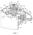
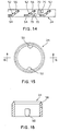
- the pressure cooker comprises in a traditional manner a container 10 whereon a lid 12 for closing the container 10 is mounted, whose respective edges both have respective jutting projections 14, 16 suitable for mutually engaging one with the other and for locking the lid 12 on the container 10 following a relative rotation between the lid 12 and the container 10.
- said container 10 and said lid 12 each have respective handles 18, 18' and 20, 20', of which handles 18 and 20 are intended to engage one with the other, by means of a suitable part for engaging and locking rotation 15, and to lock, following a rotation, the lid 12 onto the container 10.
- handles 20, 20' of the lid are mobile with the latter between a position of opening of the cooker, shown by a dotted line in Figure 2, wherein they are angularly distanced in relation to the handles 18, 18' of the cooker, and a position of closure shown by an unbroken line in said Figure 2, wherein they are arranged above said handles 18, 18' of the cooker.
- the lid of the cooker 12 also comprises an aperture 22 at which a working valve 24 is attached for releasing the steam produced by cooking, having a shutter 23 for closing said aperture 22, and a passage 26 wherein a safety pin 28 slides to lock opening of the cooker, suitable for preventing opening of the lid 12 when the internal pressure is still above a predetermined safety pressure.
- the device for actuating the valve of the pressure cooker comprises a control lever 30 angularly mobile and selectively positionable in predetermined angular positions of actuation, a cylindrical body 32 with a longitudinal axis L, attached rotatably to said lid 12 so as to rotate around said longitudinal axis and integral with said lever 30 to rotate with the latter, a slider 34 for raising said shutter 23 of the valve 24, also cylindrical, concentric and inside said cylindrical body 32.
- Said raising slider 34 is integral with said lid 12 so as to be mobile in the sole direction of said longitudinal axis L.
- suitable cam means are provided between said slider 34 and said cylindrical body 32, for driving the axial movement of said slider 34 following a rotation of said cylindrical body 32.
- said control lever 30 projects from the handle 20 of the lid 12 through an arched slit of the latter denoted by reference numeral 35 at which suitable reference indications marked by the letters "A” and “S” and by the numbers “1” and “2” are provided on the handle 20 to distinguish different ways of operating of the system and whose meaning will be further explained hereinbelow.
- said actuation body 32 is in the form of a hollow cylinder which has a radial arm 36 wherefrom said control lever 30 with a general "L" shape projects above and a block 37 for actuating said part for engaging and locking 15 together the handles 18, 20 projects below.
- a finger 38 projects radially and is angularly displaced in relation to the radial path described by said arm 36. Said finger 38, as shown in Figures 1 and 8, interferes during the movement of rotation of said cylindrical body 32 with the axial sliding path of said safety pin 28.
- a cylindrical stem 40 is provided, wherefrom a vent 42 extends above and wherein a central longitudinal hole 44 is formed, open at both ends.
- Said stem 40 is, in a traditional manner, firmly attached to said lid 12 by means of a perforated nut 45 which is screwed to the lower threaded portion 48 of said stem 40 projecting below the lid 12 through said aperture 22.
- said stem 40 defines a pivoting element for said actuation body 32 and also has on the two opposite sides of its external surface two vertical grooves 46 suitable for guiding the vertical movement of said slider 34.
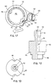
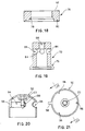
- FIGS 10 and 11 also show that said cylindrical actuation body 32 has below an annular flange 49 for supporting said slider 34 and provided with holes 51 for the percolation of the condensate and of the cooking steam residues released from the working valve 24.
- Said flange 49 is longitudinally restrained by the annular shoulder 55 of the stem 40 whereon it rotates by means of its internal edge 49'.
- Said slider 34 which is shown in greater detail in Figures 14 to 16, is in the form of a short, hollow and cylindrical element which has on its internal surface vertical ribs 50 which are suitable for insertion in the grooves 46 of said block 40, so that each rotation of the slider 34 is prevented but its free sliding along the longitudinal axis L is permitted.
- said slider 34 is placed coaxially to the interior of said actuation body 32 and has on its external lateral surface, as shown in Figure 14, three sliding grooves 52 in which three pintles 53 (shown in Figure 10) are inserted which extend radially from the lateral internal surface of said cylindrical body 32. Said grooves 52 and said pintles 53 define said cam means, allowing driving, following a rotation of said actuation body 32, of the axial movement of the slider 34.
- said pintles 53 are angularly distanced one from the other by 120°, while said sliding grooves 52 each have a first short horizontal section 54 situated at the lower edge of said slider 34 wherefrom an oblique section 56 for driving raising of said slider 34 extends.
- the cylindrical slider 34 also has an upper tapered edge 58 for engaging and raising said shutter of the valve.
- Said means for stopping rotation of said lever 30 comprise, as shown in Figure 17, a flexible element 60 in the form of a shaped metal wire which has an end 62 for insertion in a vertical slot 64 formed in a protuberance 66 which extends upwards from said arm 36 of said actuation body and is arranged between said lever 30 and said cylindrical actuation body 32, as is shown more clearly also in the previously described Figures 9 to 11.
- said vertical grooves 70 which define sort of positioning notches, have a different height one from the other due to the fact that the slider 34 has in the various angular working positions a different height position.
- first cylindrical extra weight 72 integral with the shutter 23 of said working valve 24 is a first cylindrical extra weight 72, shown more clearly in Figure 19, while a second extra weight 74, in the form of an annular element coaxial and external to said first extra weight 72 in respect whereof it is axially sliding and resting on the latter by means of respective and opposite annular and conical engaging bands 76 and 78 respectively, is shown in Figure 18.
- said second annular extra weight 74 also has an annular housing 80 for engaging the upper edge 58 of said raising slider 34.
- the reference numeral 82 denotes the edge or upper annular face of said second annular weighting element 74, suitable for engaging portions of the external casing of the valve for raising the latter and the total opening of the valve itself, as will be explained further hereinunder.
- said first extra weight 72 has a series of radial holes 84 angularly distanced for the release of the steam, as well as a threaded hole 88 wherein the shutter 23 is screwed and which has correspondingly, as shown in Figure 20, external attachment threading 90.
- Said external protection casing 92 has horizontal slits 94 for the release of the steam and internally a series of fins or radial projections, more particularly three fins which are angularly distanced one from the other at 120°, denoted by reference numeral 96, whose lower edge can be engaged by the upper annular face or edge 82 of said second annular extra weight 74, when the latter is raised by the slider 34.
- the external extra weight 74 is also raised, which in turn raises the casing 92 and the shutter 23 of the working valve integral therewith, so as to allow complete release of the steam from inside the cooker.
- Said casing 92 also has an external fin 98 which extends radially and engages in a suitable housing 100 provided in the handle 20 of the lid, as shown in Figure 2, to prevent any undesirable rotation of said casing 92, and thus prevent one of the slits 94 from positioning turned towards the lever 30 and the release of steam through the latter from causing heating of said pushbutton and the risk of burning of the user.
- said handle 20 attached to the upper lid has a convex upper surface wherein a substantially circular hole 102 is formed in an approximately central position to house said working valve 24 and having a kind of serration defining said housing 100 for the fin 98 of the casing 92, and at the sides of the latter a smaller circular hole 104 for the passage of said safety pin 28 and an arched slit 106 for the passage of said control lever 30 respectively.
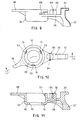
- Said engaging and locking part 15, as can be understood better by referring also to Figure 23, is in the form of a shaped plate having a tooth 108 which is inserted in a housing 110 of the handle 18 attached to the container of the cooker, shown in Figure 24, achieving locking of the handles of the cooker.
- Said engaging and locking part 15 has a hole 112 wherein, as shown in Figures 6 and 7, a pin 114 is inserted and which allows it to be pivoted to said handle 20 attached to the upper lid 12 and is also subjected to the action of a return spring 116 in a preloaded condition to maintain said tooth 108 of the engaging and locking part 15 inserted in the housing 110 of the lower handle 18 and maintain the lid 12 locked on the container 10.
- said engaging and locking part 15 has a trigger 118 whereon, following a rotation of the lever 30 and of the actuation body 32 integral therewith, the block 37 of said actuation body engages to remove said tooth 108 from the housing 110 and allow disengaging between the handles and opening of the cooker.
- the operation of the system provides, in short, four working conditions corresponding to four diferent angular working positions for the lever 30 distinguished on the handle 20 of the lid by the aforementioned references A, S, 1 and 2 which mean, respectively, the letter A, a condition of opening of the lid, the letter S, a condition of total release of steam from inside the cooker, the reference numeral 1, a first condition of cooking at a predetermined pressure for example 0.5 bar, and finally the reference numeral 2, a second condition of cooking for foods which require more intensive treatment wherein cooking takes place at a higher predetermined pressure than the previous one, for example 1 bar.
Landscapes
- Engineering & Computer Science (AREA)
- Food Science & Technology (AREA)
- Cookers (AREA)
- General Preparation And Processing Of Foods (AREA)
Description
- The present invention relates to a pressure cooker comprising a device for controlling the working valve.
- Traditional pressure cookers generally comprise a container, whereon a closure lid is mounted, with the edge of the latter and the edge of the container which both have respective jutting projections, suitable for engaging reciprocally one with the other and for locking the lid on the container, following relative rotation between the lid and the container, and each comprising at least one respective handle, these two handles being mobile between an opening position of the lid, wherein they are angularly distanced, and a closure position wherein they are on top of each other. The lid of the cooker has an aperture at which a working valve is attached for releasing the steam produced by cooking, when the internal pressure has reached a predetermined level. Said working valve has a shutter for closing said aperture.
- In traditional cookers the working valve, generally of the gravity type, is usually arranged in a substantially central position of the lid, so that, when cooking has ended and the cooker has to be opened by manually acting on said valve to release the pressure inside the cooker, the user of the cooker risks burning his or her hand with the pressurised steam which is released from the cooker or by accidentally touching the boiling lid.
- Gravity valves for pressure cookers are likewise known which are suitable for allowing cooking at two different levels of pressure. In some known valves the gravity element of the valve is simply replaced by another element of different weight according to cooking needs. Other types of valve have a lever for controlling the pressure setting which is located directly on the working valve arranged virtually in the centre of the lid. Here too, therefore, when the user goes to actuate the valve to change the cooking pressure, he or she runs the risk of being burnt due to inopportune contact with the hot lid or due to reverberations of heat from the flames of the gas ring at the side of the cooker.
- Some types of pressure cookers currently in use have the handle of the lid which engages with the handle of the container, via a suitable rotation locking and engaging part, so as to lock, following a rotation, the lid on the container. They also have a passage in the lid through which a safety pin, for locking opening of the cooker, slides, which pin, when it rises through the effect of the pressure in the cooker, engages directly with the handle of the lid, preventing its relative rotation in relation to the handle of the cooker container, thus preventing opening of the cooker if the pressure inside the latter is still above a predetermined safety level.
- In this way, hopefully, the lid cannot be opened if there is a minimum hazardous internal pressure. If this were to occur, the unexpected release of boiling steam contained in the cooker could burn an insufficiently cautious user.
- More particularly, some pressure cookers of a known type have, on the handle attached to the lid, a pushbutton which controls the mechanism for engaging and locking of the relative rotation of the handles. Said control pushbutton, in order to allow disengaging of the handles and opening of the pressure cooker, moves in a radial direction and is pushed by a preloaded spring into a backward position of locking the opening. In order to open the cooker the pushbutton has to be pressed hard with a finger, so as to push it towards the centre of the lid, while the rest of the hand is used to grasp the upper handle. At the same time the other hand is used to grasp the underlying handle and attempts are made to rotate the two handles one in relation to the other. During the whole opening operation, due to the preloaded spring acting on the opening control pushbutton, the pressure of the finger has to be maintained permanently on this pushbutton. The pressure exerted on the pushbutton must above all be of a certain extent given the considerable elastic reaction of this thrust spring. The opening manoeuvre in these traditional cookers is therefore particularly difficult and especially if the user of the cooker is an elderly person in poor physical conditions.
- In traditional pressure cookers, the abovementioned mechanism for safe opening of the cooker is completely separate from the working valve of the cooker.
- A further pressure cooker is described in EP-A-424 305.
- The object of the present invention is that of providing a device for controlling a working valve of a pressure cooker such as to avoid the disadvantages shown by similar devices hitherto known, in particular of providing a mechanism for controlling the working valve whereby any risk of burning for the user of the cooker is avoided.
- Another object of the present invention is that of providing in a pressure cooker a centralised mechanism for controlling opening of the cooker and of the working valve. Yet another object is that of providing a centralised system for controlling opening of the working valve such that no opening of the cooker is possible if the cooker contains pressurised, overheated steam.
- The first object is achieved by providing a device for controlling the working valve of a pressure cooker which, according to the disclosure in the characterising part of
claim 1, comprises, at said handle of the lid, a control pushbutton which is angularly mobile and which can be selectively positioned in predetermined angular positions of actuation, and, below the shutter of the valve, a cylindrical body, having a longitudinal axis, attached to said lid in order to rotate around said longitudinal axis and integral with said pushbutton to rotate with the latter, and a raising slider for said shutter of the valve, also cylindrical, coaxial and facing said cylindrical body, said raising slider being integral with said lid so as to be mobile axially in the direction of said longitudinal axis and cam means provided between said slider and said cylindrical body for driving the axial movement of said slider for raising the shutter following a rotation of said control pushbutton. - In this way it is possible, by acting on the pushbutton arranged at the handle in heat-insulating material, to actuate the working valve without any risk of burning.
- Moreover, without the elastic means acting on the control pushbutton, it is not necessary to maintain a pushing action permanently thereon. The pushbutton is made to rotate and is positioned in the required angular position of working of the system and all the fingers of the hands can be used to act on the handles to open the cooker.
- With the present invention definitely simple opening of the cooker without requiring excessive effort is provided.
- Basing on a system for controlling the valve constructed in this way, it is possible, according to a further innovative feature, to provide centralised control suitable for controlling both the working valve and the part for locking the handles. This is achieved according to the present invention, providing, according to the disclosure of the characterising part of
claim 2, a block integral with said actuation body for controlling, following a rotation of the control pushbutton, said part for engaging and locking the handles together, such as to engage and disengage respectively the handles one in respect of the other. - Moreover, according to a further innovative feature of the present invention, with this centralised control opening of the cooker can be prevented when there is still pressurised steam inside. This is obtained, according to the disclosure of the characterising part of claim 3, by providing a finger which extends radially from said cylindrical body, which finger interferes during the movement of rotation of said cylindrical body with the axial sliding path of said safety pin, in such a way that when the pressure inside the cooker is still high, the engaging of the finger with the safety pin in a raised position prevents further rotation of the cylindrical body and actuation by the control block of the respective part for locking the handles together.
- The present invention will in any case be made clearer on reading the following description, relating to a preferred embodiment of the invention, to be read with reference to the accompanying drawings, in which:
- Figure 1 is a partial view in longitudinal section of the pressure cooker whereon the system of the present invention is mounted;
- Figure 2 is a view from above of the pressure cooker whereon the system of the present invention is mounted;
- Figures 3 to 5 are sectioned views showing the working valve and the actuation device according to the preferred embodiment of the present invention, in three different working positions;
- Figures 6 and 7 are sectioned views taken along line 6-6 of Figure 1, showing in particular the part for engaging the handles of the cooker in two different working positions, i.e. in a position of locking together of the handles and in a position of disengaging of the handles respectively;
- Figure 8 is a view from above of the handle of the lid which indicates the different working positions of the device assumed by the device of the present invention;
- Figure 9 is a side view of the block comprising the cylindrical actuation body, the control pushbutton, the block for actuation of the part for engaging and locking the handles together and the finger for engaging the safety pin;
- Figure 10 is a view from above of the block of Figure 9;
- Figure 11 is a sectioned view taken along line 11-11 of Figure 10 relating to the block in Figures 9 and 10;
- Figure 12 is an elevated view, partially sectioned, of the central stem of the working valve;
- Figure 13 is a view from above of the stem of Figure 12;
- Figure 14 is a projected view of the lateral surface of the slider of the present invention;
- Figure 15 is a view from above of the slider of the present invention;
- Figure 16 is a sectioned view, taken along the line 16-16 of Figure 15, of the slider of the present invention;
- Figure 17 is a view from above of the actuation block alone, showing said positioning part of the present invention; Figure 18 is a sectioned view of the second extra weight of the valve of the device of the present invention;
- Figure 19 is a sectioned view of the first extra weight integral with the shutter of the valve of the present invention;
- Figure 20 is a sectioned view taken along line 20-20 of Figure 21 of the protective casing of the valve of the present invention;
- Figure 21 is a view from below again of the protective casing of the valve of the present invention;
- Figure 22 is a view from above of the upper handle attached to the lid of the cooker;
- Figure 23 is a side view of the part for engaging and locking together the handles of the cooker;
- Figure 24 is a view from above of the lower handle attached to the container of the pressure cooker.
-
- As shown in Figure 1, the pressure cooker comprises in a traditional manner a
container 10 whereon alid 12 for closing thecontainer 10 is mounted, whose respective edges both haverespective jutting projections lid 12 on thecontainer 10 following a relative rotation between thelid 12 and thecontainer 10. - With reference also to Figure 2, it can be seen that said
container 10 and saidlid 12 each haverespective handles rotation 15, and to lock, following a rotation, thelid 12 onto thecontainer 10. - These handles 20, 20' of the lid are mobile with the latter between a position of opening of the cooker, shown by a dotted line in Figure 2, wherein they are angularly distanced in relation to the
handles 18, 18' of the cooker, and a position of closure shown by an unbroken line in said Figure 2, wherein they are arranged above saidhandles 18, 18' of the cooker. - The lid of the
cooker 12 also comprises anaperture 22 at which a workingvalve 24 is attached for releasing the steam produced by cooking, having ashutter 23 for closing saidaperture 22, and apassage 26 wherein asafety pin 28 slides to lock opening of the cooker, suitable for preventing opening of thelid 12 when the internal pressure is still above a predetermined safety pressure. - According to the present invention, the device for actuating the valve of the pressure cooker comprises a
control lever 30 angularly mobile and selectively positionable in predetermined angular positions of actuation, acylindrical body 32 with a longitudinal axis L, attached rotatably to saidlid 12 so as to rotate around said longitudinal axis and integral with saidlever 30 to rotate with the latter, aslider 34 for raising saidshutter 23 of thevalve 24, also cylindrical, concentric and inside saidcylindrical body 32. Said raisingslider 34 is integral with saidlid 12 so as to be mobile in the sole direction of said longitudinal axis L. According to the invention, suitable cam means are provided between saidslider 34 and saidcylindrical body 32, for driving the axial movement of saidslider 34 following a rotation of saidcylindrical body 32. - As shown, said control lever 30 projects from the
handle 20 of thelid 12 through an arched slit of the latter denoted byreference numeral 35 at which suitable reference indications marked by the letters "A" and "S" and by the numbers "1" and "2" are provided on thehandle 20 to distinguish different ways of operating of the system and whose meaning will be further explained hereinbelow. - As shown also with reference to Figures 9 to 11, said
actuation body 32 is in the form of a hollow cylinder which has aradial arm 36 wherefrom saidcontrol lever 30 with a general "L" shape projects above and ablock 37 for actuating said part for engaging and locking 15 together thehandles radial arm 36 projects, afinger 38 projects radially and is angularly displaced in relation to the radial path described by saidarm 36. Saidfinger 38, as shown in Figures 1 and 8, interferes during the movement of rotation of saidcylindrical body 32 with the axial sliding path of saidsafety pin 28. - With reference also to Figures 12 and 13, at said
coaxial passage aperture 22 inside saidcylindrical actuation body 32 and said slider 34 acylindrical stem 40 is provided, wherefrom avent 42 extends above and wherein a centrallongitudinal hole 44 is formed, open at both ends. Saidstem 40 is, in a traditional manner, firmly attached to saidlid 12 by means of aperforated nut 45 which is screwed to the lower threadedportion 48 of saidstem 40 projecting below thelid 12 through saidaperture 22. In an innovative manner, as will be made clearer further on, saidstem 40 defines a pivoting element for saidactuation body 32 and also has on the two opposite sides of its external surface twovertical grooves 46 suitable for guiding the vertical movement of saidslider 34. - Figures 10 and 11 also show that said
cylindrical actuation body 32 has below anannular flange 49 for supporting saidslider 34 and provided withholes 51 for the percolation of the condensate and of the cooking steam residues released from the workingvalve 24. Saidflange 49 is longitudinally restrained by theannular shoulder 55 of thestem 40 whereon it rotates by means of its internal edge 49'. - Said
slider 34, which is shown in greater detail in Figures 14 to 16, is in the form of a short, hollow and cylindrical element which has on its internal surfacevertical ribs 50 which are suitable for insertion in thegrooves 46 of saidblock 40, so that each rotation of theslider 34 is prevented but its free sliding along the longitudinal axis L is permitted. - As shown in Figure 1, said
slider 34 is placed coaxially to the interior of saidactuation body 32 and has on its external lateral surface, as shown in Figure 14, three slidinggrooves 52 in which three pintles 53 (shown in Figure 10) are inserted which extend radially from the lateral internal surface of saidcylindrical body 32. Saidgrooves 52 and saidpintles 53 define said cam means, allowing driving, following a rotation of saidactuation body 32, of the axial movement of theslider 34. - As can be seen from examination of said figures, said
pintles 53 are angularly distanced one from the other by 120°, while said slidinggrooves 52 each have a first shorthorizontal section 54 situated at the lower edge of saidslider 34 wherefrom anoblique section 56 for driving raising of saidslider 34 extends. - The
cylindrical slider 34 also has an upper taperededge 58 for engaging and raising said shutter of the valve. - According to the invention, the presence of suitable means for stopping rotation of said
lever 30 in the various predetermined angular working positions of the system is also provided. - Said means for stopping rotation of said
lever 30 comprise, as shown in Figure 17, aflexible element 60 in the form of a shaped metal wire which has anend 62 for insertion in avertical slot 64 formed in aprotuberance 66 which extends upwards from saidarm 36 of said actuation body and is arranged between saidlever 30 and saidcylindrical actuation body 32, as is shown more clearly also in the previously described Figures 9 to 11. - The
opposite portion 68 of saidflexible element 60 is inserted, passing via a throughhole 69 formed on saidactuation body 32 invertical grooves 70 angularly distanced one from the other and formed on the external lateral face of said raisingslider 34, shown more clearly in Figure 14. - As shown, said
vertical grooves 70, which define sort of positioning notches, have a different height one from the other due to the fact that theslider 34 has in the various angular working positions a different height position. - As shown in Figure 1, integral with the
shutter 23 of said workingvalve 24 is a first cylindricalextra weight 72, shown more clearly in Figure 19, while a secondextra weight 74, in the form of an annular element coaxial and external to said firstextra weight 72 in respect whereof it is axially sliding and resting on the latter by means of respective and opposite annular and conicalengaging bands - As shown in said Figure 18, said second annular
extra weight 74 also has anannular housing 80 for engaging theupper edge 58 of said raisingslider 34. Thereference numeral 82 denotes the edge or upper annular face of said secondannular weighting element 74, suitable for engaging portions of the external casing of the valve for raising the latter and the total opening of the valve itself, as will be explained further hereinunder. - Moreover, as shown in Figure 19, said first
extra weight 72 has a series ofradial holes 84 angularly distanced for the release of the steam, as well as a threadedhole 88 wherein theshutter 23 is screwed and which has correspondingly, as shown in Figure 20, external attachment threading 90. - Said Figure 20, together with Figure 21, in turn shows, in greater detail, the
external casing 92 for protecting the valve in the form of a domed element inside whereof saidshutter 23 of the valve is attached. - Said
external protection casing 92 hashorizontal slits 94 for the release of the steam and internally a series of fins or radial projections, more particularly three fins which are angularly distanced one from the other at 120°, denoted byreference numeral 96, whose lower edge can be engaged by the upper annular face oredge 82 of said second annularextra weight 74, when the latter is raised by theslider 34. In this way, by raising saidslider 34 to its maximum height, the externalextra weight 74 is also raised, which in turn raises thecasing 92 and theshutter 23 of the working valve integral therewith, so as to allow complete release of the steam from inside the cooker. - Said casing 92 also has an
external fin 98 which extends radially and engages in asuitable housing 100 provided in thehandle 20 of the lid, as shown in Figure 2, to prevent any undesirable rotation of saidcasing 92, and thus prevent one of theslits 94 from positioning turned towards thelever 30 and the release of steam through the latter from causing heating of said pushbutton and the risk of burning of the user. - As shown also in Figure 22, said
handle 20 attached to the upper lid, has a convex upper surface wherein a substantiallycircular hole 102 is formed in an approximately central position to house said workingvalve 24 and having a kind of serration defining saidhousing 100 for thefin 98 of thecasing 92, and at the sides of the latter a smallercircular hole 104 for the passage of saidsafety pin 28 and anarched slit 106 for the passage of saidcontrol lever 30 respectively. - On the external surface of the
handle 20 near saidarched slit 106 for the passage of said control lever 30 a series of reference indications "A", "S", "1" and "2" are provided, defining the different working positions of the device of the present invention. - Said engaging and locking
part 15, as can be understood better by referring also to Figure 23, is in the form of a shaped plate having atooth 108 which is inserted in ahousing 110 of thehandle 18 attached to the container of the cooker, shown in Figure 24, achieving locking of the handles of the cooker. - Said engaging and locking
part 15 has ahole 112 wherein, as shown in Figures 6 and 7, apin 114 is inserted and which allows it to be pivoted to saidhandle 20 attached to theupper lid 12 and is also subjected to the action of areturn spring 116 in a preloaded condition to maintain saidtooth 108 of the engaging and lockingpart 15 inserted in thehousing 110 of thelower handle 18 and maintain thelid 12 locked on thecontainer 10. - In the figures it is also shown how said engaging and locking
part 15 has atrigger 118 whereon, following a rotation of thelever 30 and of theactuation body 32 integral therewith, theblock 37 of said actuation body engages to remove saidtooth 108 from thehousing 110 and allow disengaging between the handles and opening of the cooker. - The operation of the system provides, in short, four working conditions corresponding to four diferent angular working positions for the
lever 30 distinguished on thehandle 20 of the lid by the aforementioned references A, S, 1 and 2 which mean, respectively, the letter A, a condition of opening of the lid, the letter S, a condition of total release of steam from inside the cooker, thereference numeral 1, a first condition of cooking at a predetermined pressure for example 0.5 bar, and finally thereference numeral 2, a second condition of cooking for foods which require more intensive treatment wherein cooking takes place at a higher predetermined pressure than the previous one, for example 1 bar. - More particularly, when the
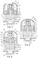
lever 30 is positioned, as shown by a dotted line in Figure 8, in the first working position at the reference "2" on the handle of the cooker, the various parts of the valve are positioned as shown in Figure 3. This Figure 3 shows how the external mobileextra weight 74 in this working condition rests on the internalextra weight 72 so that the weight of both the extra weights bears on theshutter 23, which thus closes theaperture 44 of thecentral stem 40. In this condition theslider 34 is completely lowered, while, as shown in Figure 6, theblock 37 is in the dotted line position denoted by 2 in Figure 6 and thetooth 108 of the lockingpart 15 is inserted in thehousing 110 of thelower handle 18 and saidhandles - In the second working position, wherein the
lever 30 is arranged at the reference "1" on thehandle 20 of the cooker, as shown by a dotted line in Figure 8, the parts of the valve are arranged as shown in Figure 4, where the externalextra weight 74 is raised from the support on the internalextra weight 72 by means of theslider 34 which rises into an intermediate position on command of said drive means following rotation of thecylindrical actuation body 32 caused by rotation of thelever 30 and cooking takes place at the minimum cooking pressure of 0.5 bar. In this working condition, as shown in Figure 6, theblock 37 is in the dotted line position denoted by 1 and thetooth 108 of the lockingpart 15 remains inserted in thehousing 110 of thelower handle 18 with saidhandles - In the third working position wherein the
lever 30, as shown by the unbroken line in Figure 8, is positioned at the reference "S" on thehandle 20 of the lid, the parts of the valve assume the positions indicated in Figure 5 with theactuation body 32 which, thanks to the aforementioned cam means, raises theslider 34 to its maximum height, which in turn raises the externalextra weight 74 which engages with itsupper edge 82 thefins 96, raising theprotective casing 92 which draws theshutter 23 and the firstextra weight 72 integral therewith, thus forcing the opening of theaperture 44 of thecentral stem 40 of the valve and connecting the interior of the cooker with the outside and causing the complete release of the steam. This is in fact the working condition known as total release. As shown in Figure 6, in this condition theblock 37 for actuating thepart 15 for engaging and locking the handles together is in the position indicated by an unbroken line and denoted by the reference S and does not therefore act on thetrigger 118 of the latter and thereturn spring 116 maintains thetooth 108 inserted in thehousing 110 of thehandle 18 of the cooker. In this condition too it is not possible to open the pressure cooker. - Now, if due to any malfunctioning of the valve or because the user has opened the cooker too soon and the pressure inside the cooker does not reach a safety level, for example of 0.04 bar, as shown in Figure 1 the
pin 28 remains raised and, due to the engaging against the latter by thefinger 38 integral with thebody 32, means that it is impossible to change from position "S" to position "A" and the cooker cannot be opened. Thus any risk of burning for the user of the cooker is avoided. - In the fourth working condition wherein the
lever 30 is arranged, as shown by the dotted line in Figure 8, at the reference "A" on thehandle 20 of the lid of the cooker, the various parts of the valve are positioned as in the previous position S and is again documented by Figure 5 with theactuation body 32 which maintains theslider 34 raised, which in turn holds the externalextra weight 74 raised and hence raises theprotective casing 92 and theshutter 23, leaving theaperture 44 of thecentral stem 40 open. In this condition, as shown in Figure 7, theblock 37, following further rotation of thelever 30, pushes thetrigger 118 and makes the engaging and lockingpart 15 rotate on thepin 114, opposing thereturn spring 116 and causing the release of thetooth 108 from thehousing 110 of thehandle 18. In this condition the twohandles - It is naturally understood that what has been written and shown in reference to the preferred embodiment of the present invention has been given purely by way of a non- limiting example of the principle claimed.
Claims (17)
- Pressure cooker of the type comprising a container (10) whereon a lid (12) is mounted for closure of the container (10), the edge of the latter and the edge of the container (10) both having respective jutting projections (14, 16) suitable for engaging reciprocally one with the other and for locking the lid (12) on the container (10) following a relative rotation between the lid (12) and the container (10), and each comprising at least one respective handle (18,20), said handles (18,20) being mobile between a position of opening of the lid (12), wherein they are angularly distanced, and a position of closure, wherein they are one on top of the other; the lid (12) comprising an aperture (22) at which a working valve (24) is attached for releasing the steam produced by cooking, said working valve (24) having a shutter (23) for closing said aperture (22); characterised in that it comprises, at said handle (20) of the lid (12), a control lever (30) which is angularly mobile and selectively positionable in predetermined angular actuation positions, and below said shutter (23) of the valve (24), a cylindrical body (32), having a longitudinal axis, attached to said lid (12) so as to rotate around said longitudinal axis and integral with said lever (30) to rotate with the latter, a raising slider (34) for said shutter (23) of the valve (24), also cylindrical, coaxial and facing said cylindrical body (32), said raising slider (34) being rotatably fixed with respect to said lid (12) so as to be axially mobile in the direction of said longitudinal axis and cam means provided between said slider (34) and said cylindrical body (32) for driving the axial movement of said slider (34) for raising the shutter (23) following a rotation of said control lever (30).
- Pressure cooker according to claim 1, wherein said handles (18, 20) of the pressure cooker are intended to engage one with the other, by means of a suitable part for engaging and locking rotation (15) and for locking, following a rotation, the lid (12) on the container (10); characterised in that it comprises a block (37) integral with said actuation body (32) for control, following rotation of the lever (30), of said part (15) for engaging and locking together the handles (18,20), such as to engage, and disengage respectively, said handles (18,20) one in respect of the other.
- Pressure cooker according to claim 1 or 2, wherein the lid (12) of the pressure cooker comprises a passage (26) wherein slides a safety pin for locking opening of the cooker (28), designed to prevent opening of the lid (12) when the internal pressure is still above a predetermined safety pressure; characterised in that it comprises a finger (38) which projects radially from said cylindrical body (32), said finger (38) interfering during the movement of rotation of said cylindrical body (32) following rotation of the control lever (30) with the axial sliding path of said safety pin (28).
- Pressure cooker according to any one of the previous claims, characterised in that said shutter (23) of said working valve (24) for the closure of said aperture (22) is integral with a first cylindrical extra weight (72), whereon a second annular extra weight (74) can be rested, coaxial and outside of said first cylindrical extra weight (72) and axially mobile in respect thereof, said second external annular extra weight (74) having a lower engaging surface for said raising slider (34).
- Pressure cooker according to claim 4, wherein said working valve (24) comprises an external protective casing (92) having slits (94) for the release of the steam whereto the shutter (23) is integral, characterised in that said casing (92) has internally at least one radial projection (96) for engaging and raising by an upper edge (82) of said external annular extra weight (74).
- Pressure cooker according to claim 4, characterised in that said slider (34) has an upper tapered or pointed edge (58) suitable for engaging in an annular groove (80) provided in the lower engaging surface of said second extra weight (74).
- Pressure cooker according to claim 1, characterised in that said cam means comprise at least a first, a second and a third pin (53), angularly distanced at 120° one from the other and which extend radially from said cylindrical body (32) and are inserted in corresponding sliding grooves (52), substantially helical, provided on the lateral surface of said slider (34) facing said cylindrical body (32), and vertical ribs (50) for preventing longitudinal sliding and rotation provided on said slider (34), suitable for inserting in corresponding vertical grooves (46) integral with said lid (12).
- Pressure cooker according to claim 7, characterised in that said substantially helical sliding grooves (52) each have an initial short horizontal section (54), situated at the lower edge of said slider (34), wherefrom an oblique section (56) extends for controlling raising of said slider (34).
- Pressure cooker according to claim 1, characterised in that it comprises means for stopping rotation of said lever (30) in the predetermined angularworking positions.
- Pressure cooker according to claim 9, characterised in that said means for stopping rotation of said lever (30) comprise a flexible element (62) having one end (64) integral with said lever (30) and with said cylindrical actuation body (32) and a portion (68) for insertion in vertical grooves (70) angularly distanced one from the other and formed on the external face of said raising slider (34).
- Pressure cooker according to claim 7, characterised in that at said passage aperture (22), coaxial and concentric with said cylindrical actuation body (32) and said slider (34), a cylindrical stem (40) is provided wherein a central longitudinal hole (44) is formed, open at both ends, said stem (40) being firmly attached to said lid (12), defining a pivoting element for said actuation body (32) and having on its external surface said vertical grooves (46) wherein said vertical ribs (50) of said slider (34) are freely inserted, sliding in an axial direction.
- Pressure cooker according to claim 2, characterised in that said engaging and locking part (15) is in the form of a shaped plate having an actuation trigger (118) for a tooth (108) for engaging said handle (18) attached to the container (10), said engaging and locking part (15) being pivoted to said handle (20) attached to the upper lid (12) and being subjected to the action of preloaded elastic means (116) for maintaining said part (15) for engaging and locking the handles together in an engaged condition.
- Pressure cooker according to claim 1, characterised in that said cylindrical actuation body (32) has below an annular support flange (49) for said slider (34) provided with holes (51) for percolation of the condensate and of the residues of the cooking steam released from the working valve (24).
- Pressure cooker according to claim 5, characterised in that said casing (92) has an external fin (98) which extends radially and engages in a suitable housing (100) provided in the handle (20) for preventing any rotation of said casing (92).
- Pressure cooker according to claim 1, characterised in that said handle attached to the upper lid (20) has a convex surface wherein a substantially circular hole (102) is formed for housing said working valve (24) having a sort of tooth (100) defining said housing for the external fin (98) of the casing (92) for the passage of said safety pin (28) and an arched slit (106) for the passage of said control lever (30).
- Pressure cooker according to claim 15, characterised in that said handle (20), at said arched slit (106) for the passage of said control lever (30), has a series of reference indications defining working positions of the system.
- Pressure cooker according to claim 12, characterised in that said handle attached to the container (18) has a housing (110) for inserting the tooth (108) of said part (15) for locking and engaging the handles (18,20) together.
Applications Claiming Priority (2)
| Application Number | Priority Date | Filing Date | Title |
|---|---|---|---|
| ITMI950700 | 1995-04-06 | ||
| IT95MI000700A IT1275723B1 (en) | 1995-04-06 | 1995-04-06 | CONTROL DEVICE OF THE WORKING VALVE OF A PRESSURE COOKER |
Publications (2)
| Publication Number | Publication Date |
|---|---|
| EP0736282A1 EP0736282A1 (en) | 1996-10-09 |
| EP0736282B1 true EP0736282B1 (en) | 2000-06-07 |
Family
ID=11371232
Family Applications (1)
| Application Number | Title | Priority Date | Filing Date |
|---|---|---|---|
| EP96104703A Expired - Lifetime EP0736282B1 (en) | 1995-04-06 | 1996-03-25 | Device controlling the working valve of a pressure cooker |
Country Status (3)
| Country | Link |
|---|---|
| EP (1) | EP0736282B1 (en) |
| DE (1) | DE69608732T2 (en) |
| IT (1) | IT1275723B1 (en) |
Cited By (1)
| Publication number | Priority date | Publication date | Assignee | Title |
|---|---|---|---|---|
| CN101209179B (en) * | 2006-12-28 | 2013-04-17 | Seb公司 | Pressure-cooking device with improved construction and corresponding manufacturing method |
Families Citing this family (7)
| Publication number | Priority date | Publication date | Assignee | Title |
|---|---|---|---|---|
| PT102076B (en) * | 1997-11-07 | 2003-11-28 | Cruzinox Ind Metalurgica Lda | SAFETY DEVICE ON OPENING AND CLOSING FOR A COOKING CONTAINER UNDER PRESSURE |
| DE19822905A1 (en) * | 1998-05-22 | 1999-11-25 | Baumgarten Heinrich Kg | Pressure cooker with a safety valve |
| FR2783686B1 (en) | 1998-09-28 | 2000-11-17 | Seb Sa | SAFETY DEVICE AT THE OPENING OF A PRESSURE COOKING APPARATUS WITH BAYONET CLOSURE |
| ES1041853Y (en) * | 1998-12-07 | 2000-01-01 | Fagor S Coop | POT EXPRESS WITH SECURITY AGAINST THE TURN OF THE LID. |
| IT246614Y1 (en) * | 1999-03-29 | 2002-04-09 | Lagostina Spa | AUTOMATIC SAFETY DEVICE FOR A PRESSURE COOKER |
| ES1056370Y (en) * | 2003-12-15 | 2004-07-01 | Fagor S Coop | REGULATION VALVE IN A PRESSURE COOKER. |
| ES2689253B2 (en) * | 2017-05-09 | 2019-04-11 | Isogona S L | PRESSURE COOKER |
Family Cites Families (6)
| Publication number | Priority date | Publication date | Assignee | Title |
|---|---|---|---|---|
| ES290269Y (en) * | 1985-11-12 | 1988-11-01 | Radar,S.Coop. | PRESSURE COOKER WITH BAYONET CLOSURE AND PESA VALVE |
| ES1011685Y (en) * | 1989-10-16 | 1990-11-16 | Fagor, S. Coop. Ltda. | PERFECT PRESSURE COOKER. |
| DE4022004C2 (en) * | 1990-07-11 | 1994-09-01 | Fissler Gmbh | Pressure cooker |
| DE4026166A1 (en) * | 1990-08-17 | 1992-02-20 | Amc Int Alfa Metalcraft Corp | COOKING TANK |
| DE4040489A1 (en) * | 1990-12-18 | 1992-07-16 | Silit Werke | COVER FOR COOKERS WITH FOLDED EDGE |
| FR2700825B1 (en) * | 1993-01-28 | 1995-04-14 | Seb Sa | Device for automatic control of a flow limitation valve. |
-
1995
- 1995-04-06 IT IT95MI000700A patent/IT1275723B1/en active IP Right Grant
-
1996
- 1996-03-25 EP EP96104703A patent/EP0736282B1/en not_active Expired - Lifetime
- 1996-03-25 DE DE69608732T patent/DE69608732T2/en not_active Expired - Lifetime
Cited By (1)
| Publication number | Priority date | Publication date | Assignee | Title |
|---|---|---|---|---|
| CN101209179B (en) * | 2006-12-28 | 2013-04-17 | Seb公司 | Pressure-cooking device with improved construction and corresponding manufacturing method |
Also Published As
| Publication number | Publication date |
|---|---|
| EP0736282A1 (en) | 1996-10-09 |
| DE69608732D1 (en) | 2000-07-13 |
| ITMI950700A1 (en) | 1996-10-06 |
| IT1275723B1 (en) | 1997-10-17 |
| ITMI950700A0 (en) | 1995-04-06 |
| DE69608732T2 (en) | 2001-02-22 |
Similar Documents
| Publication | Publication Date | Title |
|---|---|---|
| US11992145B2 (en) | Cooking appliance for cooking food with or without pressure | |
| US12089768B2 (en) | Electric cooking appliance provided with a removable heating device | |
| US20140013960A1 (en) | Cooking Utensil for Cooking Food Under Pressure that has an Improved Control Device | |
| US6394081B1 (en) | Safety knob for domestic gas apparatuses | |
| KR101083981B1 (en) | Pressure cooker lead | |
| US6648162B1 (en) | Button actuated pressure release and locking device for pressure cookers | |
| EP0736282B1 (en) | Device controlling the working valve of a pressure cooker | |
| US6523459B1 (en) | Safety device for opening a pressure cooker with lug-bayonet type closure | |
| EP0972478A2 (en) | Steam vent for cookware | |
| CZ280338B6 (en) | Pressure-cooker | |
| JPS624125B2 (en) | ||
| EP0916298B1 (en) | Opening and closing safety device for a pressure cooker | |
| WO2007140547A1 (en) | Cooking press and grill | |
| US6375150B1 (en) | Knob for gas apparatus with safety button | |
| US10051996B2 (en) | Toaster oven control knob and method of controlling a toaster oven | |
| US5154511A (en) | Trouble-light with rotatable shield | |
| CA2648899A1 (en) | Adjustable pressure cooking appliance with controlled decompression | |
| CA2311568A1 (en) | Cooking appliance | |
| EP1582122A1 (en) | Safety device for pressure cookers | |
| KR100406347B1 (en) | safty switchgear for pressure cooker | |
| JP3277134B2 (en) | Temperature sensor of cooking device | |
| JPH02271811A (en) | Pressure cooker | |
| RU2810044C1 (en) | Kitchen appliance for cooking food under pressure or without pressure | |
| KR100279189B1 (en) | Safety device of electric pressure cooker | |
| KR0126566Y1 (en) | Lid opening and closing safety device of electric pressure cooker |
Legal Events
| Date | Code | Title | Description |
|---|---|---|---|
| PUAI | Public reference made under article 153(3) epc to a published international application that has entered the european phase |
Free format text: ORIGINAL CODE: 0009012 |
|
| AK | Designated contracting states |
Kind code of ref document: A1 Designated state(s): BE DE FR IT |
|
| 17P | Request for examination filed |
Effective date: 19970327 |
|
| GRAG | Despatch of communication of intention to grant |
Free format text: ORIGINAL CODE: EPIDOS AGRA |
|
| 17Q | First examination report despatched |
Effective date: 19990318 |
|
| GRAG | Despatch of communication of intention to grant |
Free format text: ORIGINAL CODE: EPIDOS AGRA |
|
| GRAH | Despatch of communication of intention to grant a patent |
Free format text: ORIGINAL CODE: EPIDOS IGRA |
|
| GRAH | Despatch of communication of intention to grant a patent |
Free format text: ORIGINAL CODE: EPIDOS IGRA |
|
| GRAA | (expected) grant |
Free format text: ORIGINAL CODE: 0009210 |
|
| AK | Designated contracting states |
Kind code of ref document: B1 Designated state(s): BE DE FR IT |
|
| REF | Corresponds to: |
Ref document number: 69608732 Country of ref document: DE Date of ref document: 20000713 |
|
| ITF | It: translation for a ep patent filed | ||
| ET | Fr: translation filed | ||
| PLBE | No opposition filed within time limit |
Free format text: ORIGINAL CODE: 0009261 |
|
| STAA | Information on the status of an ep patent application or granted ep patent |
Free format text: STATUS: NO OPPOSITION FILED WITHIN TIME LIMIT |
|
| 26N | No opposition filed | ||
| PGFP | Annual fee paid to national office [announced via postgrant information from national office to epo] |
Ref country code: BE Payment date: 20070316 Year of fee payment: 12 |
|
| PGFP | Annual fee paid to national office [announced via postgrant information from national office to epo] |
Ref country code: IT Payment date: 20080327 Year of fee payment: 13 |
|
| BERE | Be: lapsed |
Owner name: *LAGOSTINA S.P.A. Effective date: 20080331 |
|
| PGFP | Annual fee paid to national office [announced via postgrant information from national office to epo] |
Ref country code: FR Payment date: 20080331 Year of fee payment: 13 |
|
| PG25 | Lapsed in a contracting state [announced via postgrant information from national office to epo] |
Ref country code: BE Free format text: LAPSE BECAUSE OF NON-PAYMENT OF DUE FEES Effective date: 20080331 |
|
| REG | Reference to a national code |
Ref country code: FR Ref legal event code: ST Effective date: 20091130 |
|
| PG25 | Lapsed in a contracting state [announced via postgrant information from national office to epo] |
Ref country code: FR Free format text: LAPSE BECAUSE OF NON-PAYMENT OF DUE FEES Effective date: 20091123 |
|
| PGFP | Annual fee paid to national office [announced via postgrant information from national office to epo] |
Ref country code: DE Payment date: 20100330 Year of fee payment: 15 |
|
| PG25 | Lapsed in a contracting state [announced via postgrant information from national office to epo] |
Ref country code: IT Free format text: LAPSE BECAUSE OF NON-PAYMENT OF DUE FEES Effective date: 20090325 |
|
| PG25 | Lapsed in a contracting state [announced via postgrant information from national office to epo] |
Ref country code: DE Free format text: LAPSE BECAUSE OF NON-PAYMENT OF DUE FEES Effective date: 20111001 |
|
| REG | Reference to a national code |
Ref country code: DE Ref legal event code: R119 Ref document number: 69608732 Country of ref document: DE Effective date: 20111001 |