EP0734923B1 - Einen Gurtstraffer aufweisende Sicherheitsgurtanordnung in Kraftfahrzeugen - Google Patents
Einen Gurtstraffer aufweisende Sicherheitsgurtanordnung in Kraftfahrzeugen Download PDFInfo
- Publication number
- EP0734923B1 EP0734923B1 EP96101132A EP96101132A EP0734923B1 EP 0734923 B1 EP0734923 B1 EP 0734923B1 EP 96101132 A EP96101132 A EP 96101132A EP 96101132 A EP96101132 A EP 96101132A EP 0734923 B1 EP0734923 B1 EP 0734923B1
- Authority
- EP
- European Patent Office
- Prior art keywords
- fluid
- safety belt
- pressure
- drive
- belt
- Prior art date
- Legal status (The legal status is an assumption and is not a legal conclusion. Google has not performed a legal analysis and makes no representation as to the accuracy of the status listed.)
- Expired - Lifetime
Links
- 238000007789 sealing Methods 0.000 claims abstract description 51
- 239000012530 fluid Substances 0.000 claims abstract description 39
- 230000001133 acceleration Effects 0.000 claims description 13
- 230000002093 peripheral effect Effects 0.000 claims description 12
- 238000004804 winding Methods 0.000 claims description 12
- 239000004033 plastic Substances 0.000 claims description 11
- 230000001960 triggered effect Effects 0.000 claims description 6
- 239000000843 powder Substances 0.000 claims description 5
- 229910000639 Spring steel Inorganic materials 0.000 claims description 3
- 230000001419 dependent effect Effects 0.000 claims 1
- 244000144992 flock Species 0.000 claims 1
- 229910052623 talc Inorganic materials 0.000 claims 1
- 235000012222 talc Nutrition 0.000 claims 1
- 239000000454 talc Substances 0.000 claims 1
- 239000002245 particle Substances 0.000 abstract description 16
- FPAFDBFIGPHWGO-UHFFFAOYSA-N dioxosilane;oxomagnesium;hydrate Chemical compound O.[Mg]=O.[Mg]=O.[Mg]=O.O=[Si]=O.O=[Si]=O.O=[Si]=O.O=[Si]=O FPAFDBFIGPHWGO-UHFFFAOYSA-N 0.000 abstract description 2
- 230000000694 effects Effects 0.000 description 13
- 239000007787 solid Substances 0.000 description 12
- 239000000835 fiber Substances 0.000 description 5
- 239000000203 mixture Substances 0.000 description 5
- 230000008901 benefit Effects 0.000 description 4
- 238000006073 displacement reaction Methods 0.000 description 3
- 239000000463 material Substances 0.000 description 3
- 238000010276 construction Methods 0.000 description 2
- 230000008878 coupling Effects 0.000 description 2
- 238000010168 coupling process Methods 0.000 description 2
- 238000005859 coupling reaction Methods 0.000 description 2
- 238000004880 explosion Methods 0.000 description 2
- 241000533950 Leucojum Species 0.000 description 1
- 230000009471 action Effects 0.000 description 1
- 239000011324 bead Substances 0.000 description 1
- 230000005540 biological transmission Effects 0.000 description 1
- 230000000295 complement effect Effects 0.000 description 1
- 238000005553 drilling Methods 0.000 description 1
- 239000003822 epoxy resin Substances 0.000 description 1
- 230000009969 flowable effect Effects 0.000 description 1
- 239000011888 foil Substances 0.000 description 1
- LNEPOXFFQSENCJ-UHFFFAOYSA-N haloperidol Chemical compound C1CC(O)(C=2C=CC(Cl)=CC=2)CCN1CCCC(=O)C1=CC=C(F)C=C1 LNEPOXFFQSENCJ-UHFFFAOYSA-N 0.000 description 1
- 230000012447 hatching Effects 0.000 description 1
- 230000003993 interaction Effects 0.000 description 1
- 238000000034 method Methods 0.000 description 1
- 229920000647 polyepoxide Polymers 0.000 description 1
- 230000008569 process Effects 0.000 description 1
- 238000007665 sagging Methods 0.000 description 1
- 238000009423 ventilation Methods 0.000 description 1
Images

Classifications
-
- B—PERFORMING OPERATIONS; TRANSPORTING
- B60—VEHICLES IN GENERAL
- B60R—VEHICLES, VEHICLE FITTINGS, OR VEHICLE PARTS, NOT OTHERWISE PROVIDED FOR
- B60R22/00—Safety belts or body harnesses in vehicles
- B60R22/34—Belt retractors, e.g. reels
- B60R22/46—Reels with means to tension the belt in an emergency by forced winding up
- B60R22/4628—Reels with means to tension the belt in an emergency by forced winding up characterised by fluid actuators, e.g. pyrotechnic gas generators
-
- B—PERFORMING OPERATIONS; TRANSPORTING
- B60—VEHICLES IN GENERAL
- B60R—VEHICLES, VEHICLE FITTINGS, OR VEHICLE PARTS, NOT OTHERWISE PROVIDED FOR
- B60R22/00—Safety belts or body harnesses in vehicles
- B60R22/34—Belt retractors, e.g. reels
- B60R22/46—Reels with means to tension the belt in an emergency by forced winding up
- B60R2022/468—Reels with means to tension the belt in an emergency by forced winding up characterised by clutching means between actuator and belt reel
Definitions
- the invention relates to a belt tensioner Seat belt arrangement in motor vehicles according to the preamble of claim 1.
- the dimensioning of the individual components is intended here be such that a minimum penalty length of the belt of 140 mm is achieved. However, a certain one is preferred additional feed length are available so that the Belt through the belt tensioner e.g. pulled in by a maximum of 205 mm or can be tightened.
- the aim of the invention is a belt tensioner to create the type mentioned, in which without expensive construction measures the effects of any leaks at least mitigated and preferably largely eliminated become.
- the idea of the invention can therefore be seen in the fact that one flowing into the pressurized subareas Fluid gives self-sealing properties, so when trying of the fluid, due to leaks at any point flow through, a self-sealing effect is achieved.
- the arrangement according to the invention is suitable for self-sealing especially because such a trigger responds only once in an accident or the like and is used so that it is sufficient if only within this extremely short period of action Self-sealing effect is guaranteed by the fluid.
- the fluid should preferably consist of finely divided Solid particles exist which are flowable as a whole and can be evenly distributed in a gas space.
- Fluid must not be sticky or sticky at least as long as long as there is no leak or a leak has occurred.
- compositions of the fluid can be found in the patent claims 2 to 8. Flakes are particularly preferred from tangles and / or plastic chips, because these Materials are particularly dangerous in the event of an explosion lay effectively in front of gaps and leaks and thus ensure optimal sealing of the pressure rooms.
- a compressed gas used in which when the pressure source is triggered the Fluid-forming solid particles similar to snowflakes fail which has the particular advantage that this a particularly even distribution of the fluid in the Pressure rooms is guaranteed. It is thus ensured that the solid particles forming the fluid adhere to that, if any Leakage or at any design-related gap and can develop their sealing effect there.
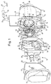
- FIG. 1 and 2 has a seat belt assembly one for example in the floor area of a passenger compartment Vehicle chassis 40 bracket 11 to be attached to the order a central axis 38 rotates a belt take-up reel 12 is attached, on which a seat belt 13 is wound is that which is only indicated by dashed lines in FIG. 1 Way via a buckle 39 and e.g. a wire rope 13 'too elsewhere in the vehicle chassis 40, wherein the seat belt 13 in the usual way to the shown body of a vehicle occupant. Further is indicated at the top right in Fig. 1 that the seat belt 13 is also part of a three-point belt arrangement can be.
- a conventional return spring assembly 14 in which a Retraction spring, not shown, is provided, which on the Belt take-up reel 12 has a light belt pull-in torque exercises so that the pulled out and put on by the vehicle occupant Seat belt so far on the belt take-up reel 12 rolls up that it lies loosely on the body of the vehicle occupant.
- a conventional return spring assembly 14 Located on one end of the belt take-up reel 12 a conventional return spring assembly 14 in which a Retraction spring, not shown, is provided, which on the Belt take-up reel 12 has a light belt pull-in torque exercises so that the pulled out and put on by the vehicle occupant Seat belt so far on the belt take-up reel 12 rolls up that it lies loosely on the body of the vehicle occupant.
- a conventional one, not shown Belt pull-out lock provided, which in the event of a sudden Tighten the seat belt 13 or in the event of an accident Accelerations takes effect and the belt take-up reel 12 in the then existing pull-in or pull-in position, so that pulling out the seat
- the return spring arrangement can also be connected to the one shown in FIG. 1 and 2 with 14 'designated end face of the belt winding roller 12 or the holder 11 may be provided, for which one in Fig. 1 indicated inner shaft 41 rotatable by appropriate central bores of a to be described below Additional drive 15 and a clutch 20 for the belt take-up reel 12 must extend and connected to this rotatably is.
- the arrangement of the return spring assembly at 14 ' has the advantage that both the normal spring drive and the additional drive of the belt take-up reel 12 of the same Face end.
- the auxiliary drive 15 includes a torque generating device 18, which one with the axis of rotation 38 of the belt take-up reel 12 coaxial drive shaft 19 comprises, on the concentrically a drive roller 22 rotatably is attached.
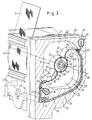
- a drive roller 22 On the drive roller 22 are in the view 1.3 anticlockwise two above each other Drawstrings made of spring steel sheet approximately 0.2 mm thick 21 wound up at fastening points 25 on the circumference the drive roller 22 are rotatably connected to this.
- the arcuate part of the drawstrings 21 lies with its concave surface in the starting position shown in Figure 3 of the belt tensioner curved in the radial direction trained sealing walls 29 to the housing 24 are integrally formed and crescent-shaped in essentially radially inward to the on the drive roller 22 wound layers of the drawstrings 21 and extend there each form a tapered sealing lip 31, the one Sealed connection with the wound tension bands 21 guaranteed.
- branch lines 27 and 28 by one common pressure chamber 17 originate from a pressure source 16 can be acted upon.
- the pressure source 16 is via an in 3 dashed control line 42 with a also only dashed-line acceleration sensor 43 connected, in the event of an accident-related vehicle acceleration ignites a pyrotechnic charge in the pressure source 16, so that a pressure builds up suddenly in the pressure chamber 17 can be.
- a pressure builds up suddenly in the pressure chamber 17 can be.
- branch lines 27, 28 open out at the strip running spaces 23 that they are on the circumference of the tape running spaces 23 across the mouth of the branch lines 27, 28 extending tension bands 21 can apply pressure.
- the torque generating device drives 18 when the pyrotechnic charge is ignited 16 the drive shaft 19, which is hollow for receiving the inner shaft 41 is in the belt winding direction.
- clutch 20 provided which is usually disengaged, for an unhindered interaction between the return spring assembly 14 'and the To ensure belt winding roller 12 via the inner shaft 41. Only when an accidental acceleration occurs and the torque generating device 18 the belt 13 should tighten suddenly, the clutch 20 must engage to the torque generated by the torque generating device 18 to be able to transfer to the belt take-up reel 12.
- the drive roller 22 is on its from the torque generating device 18 axially facing away with axially or radially projecting wedge cams 55, which in complementary peripheral slots 56 on the outer edge a central bore of a clutch disc 44 such intervene that in the circumferential direction a certain game between the wedge cams 55 and the peripheral edges of the Circumferential slots 56 exist, however, that the drive roller 22nd after overcoming this play, the clutch disc 44 to a rotational movement.
- the clutch disc 44 detects on its outer circumference Fig. 1 projecting radially outwards and over its circumference distributed retaining cams 50 on the rear of the clutch housing 58 radially inward into the receiving cavity 60 for the Grip clutch disc 44 projecting counter cams 57, such that the front of the drive roller 22 or an adapter attached to it in the direction of Belt take-up reel 12 advanced clutch disc 44 radially outside first of the counter cams 57 against axial displacement is held.
- the springy material in particular spring steel existing clutch disc 44 resiliently conically deformed.
- the clutch disc is located 44 normally in the disengaged position, so that the belt winding roller 12 is unhindered by the Drive roller 22 can rotate freely and only with the return spring arrangement 14 'cooperates via the inner shaft 41 which extends through the bore 67.
- the slider 48 has an operating rod 48 ′′ and below an enlarged piston area 48 'with a breakable Valve wall 59 on. Below the lower front of the piston area 48 'is the pyrotechnic charge 16. From the displacement recess 49 branches in the direction a pressure channel 61 from the torque generating device 18, which is in flow connection with the pressure chamber 17.
- the generally cylindrical pyrotechnic Charge 16 can according to FIG. 1 on the belt reel 12 facing side of the clutch 20 parallel to and below the belt winding roller 12 may be arranged. It is essential that with ignition of the pyrotechnic charge 16 initially only the slider 48 and only after engaging the clutch 20 the torque generating device 18 is pressurized becomes.
- the individual grains this powder should at least be slightly larger than the gap between the edges of the drawstrings 21 and the neighboring ones End faces 51, 52. Leaks can also between the web between the sub-spaces 23 "and the feed lines 27, 28 be present.
- the fluid 63 is therefore preferably from solid particles finely distributed in the compressed gas, whose dimensions are such that they are determined by the construction-related Column on the pressurized sub-rooms 23 'at least for the most part cannot pass through, i.e. when the compressed gas passes through these leaks and gaps are held and thus develop their sealing effect can.
- the fluid-forming solid particles are short fibers or Flakes from a tangle of fibers. You can go on with something special Advantage film or sheet-shaped plastic chips use, whose length dimensions are about 0.5 mm should.
- the individual foil or sheet-like particles of the Fluids then lay in front of any when the compressed gas expands Leaks or gaps and seal them with it optimally.
- the fluid also comes in finely divided form in the compressed gas Plastic balls with a diameter of the order of magnitude of 0.1 mm, as used, for example, as filling material for Find epoxy resins.
- the sealing effect is during a Compressed gas expansion is particularly effective because in Area of leaks or gaps an acceleration of the compressed gas takes place, which leads to a concentration of therein solid particles distributed in fluid at these points results in an optimal seal leads.
- the operating principle of the operated belt tensioner is as follows: If the acceleration sensor 43 (FIG. 3) detects an acceleration due to an accident on the vehicle, it triggers the pyrotechnic charge 16 via the control line 42. Thereupon, as shown in FIGS. 3 and 4 for the sake of illustration, this does not initially act on the torque generating device 18, but rather only on the piston region 48 'of the slide 48 according to FIG. 1, so that it is moved from the rest position into the coupling position and takes the clutch disc 44 to a rotary movement.
- the displacement of the slide 48 and the rotational movement of the Clutch disc 44 are calculated so that in the first stage the movement of the holding cams 50 and the counter cams 57 except Engage, whereupon the clutch disc 44 in the direction the front guide plate 47 snaps.
- the engagement cams 46 engage in the engagement recesses 45, if these two elements are randomly aligned axially should. If this is not already the case, lay the webs 69 of the clutch disc 44 to the engagement cams 46 on. Now the clutch disc 44 in one second stage of the movement of the slide 48 rotated further, until finally the engagement recesses 45 over the engagement cams Snap 46.
- the circumferential slots 56 must be one of the two stages of movement enabling rotation of the clutch disc 44 relative to the drive roller 22 or the wedge cam 55.
- the expansion gas from the pyrotechnic charge 16 accelerates also the powder in the feed lines 27, 28 63 or the plastic chips, fibers, Fibers, flakes or plastic balls, so that 4 completely into the pressurized Spread out subspaces 23 'fluidly and together with the expansion gas mixed with it due to any leaks try to step through.
- Solid particles due to the choice of grain or solid particle size according to the invention however at the entrance to the existing column hang and thereby lead to a sealing effect, which a substantial pressure increase in the sub-rooms 23 ' results in fast and effective belt tensioning favored.
- the sealing wall 29 faces the partial space 23 ' preferably an extension 29 '' so that the sealing lip 29 'is somewhat extended in the direction of the pressure chamber 23'.
- the extension 29 '' is flexible and could also be articulated to the actual sealing wall 29 and to be precise about a axis parallel to the drive shaft 19 Swivel axis. In this way, the sealing lip 29 'through the pressure in the subspace 23 'particularly well sealing against the Outer surface of the tension band wound on the drive roller 22 21 pressed.
- the Expansion gas supply line 27 formed storage pockets 64, in which the fluid-like powder, plastic bead mixture, flaky fiber tangle or plastic shredded mixture 63 is housed.
- the connection of the storage pockets 64 to the feed line 27 is such that when expansion gas flows out from the pressure chamber 17 through the supply line 27 in the pressurized compartment 23 'in the storage pockets 64 existing solid particles are taken away and in the way indicated in Fig. 5 completely with the expansion gas mix so that fluid gets anywhere where there are leaks to those places bring about a sealing effect according to the invention.
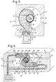
- FIG. 6 shows an embodiment similar to that of FIG. 3 and 4, however, similar to the embodiment 5 the flexible drawstrings 21 without reversing the Sense of curvature that they have on the drive roller 22, extend through the belt running spaces 23 to the peripheral wall 30 in order to there to be attached to the housing 24 at 26.
- the subspaces 23 "are on peripheral end through a vent hole 37 and then the vent duct 37 'to the surrounding atmosphere vented out.
- the expansion gas due to a suitable composition in the exhaust gas itself contains a fluid-like solid particle component 63 'which together with the expansion gas via the pressure chamber 17 through the supply lines 27, 28 into the pressurized Subspaces 23 'spreads to the feed lines 27, 28th and the pressurized compartments 23 'the desired To bring about a sealing effect.
- the main advantage of the embodiment according to FIG. 5 and 6 is that the pressure in the pressurized Subspace 23 'to the sealing lip 29' of the sealing wall or Sealing walls 29 can spread so that the freely through the Tape running spaces 23 and for the pressurization responsible traction generation area of the flexible drawstring 21 compared to the embodiment 3 and 4 significantly, in this case Embodiment around the diameter of the drive roller 22 is enlarged. At the same pressure, the the drive roller 22 moving tensile force of the flexible Drawstring 21 significantly increased.
- the flexible drawstring 21 is in solid lines shown at the beginning of a pressurization and in dashed lines in two more advanced stages a pressure release where the seat belt is already more streamlined.
- the longitudinal extent of the sealing walls 29 is particularly important essentially tangential to the drive roller 22.
- the sealing walls 29 flexible, d. H. in particular elastically resilient or, for example at 29 '' 'hinged to the housing 24, with slight spring forces on the sealing walls 29 in the direction the flexible drawstring wound on the drive roller 22 21 can be biased so that the sealing lips 29 ' slightly against the outer surface of the wound drawstring 21 be pressed.
- each pressurization leads to the subspaces 23 'facing surface of the sealing walls 29 to that this with its sealing lip 29 'against the outer surface of the pressed on the drive roller 22 wound tension band 21 be, whereby between the sealing lips 29 'and Drive roller 22 or the tension band 21 wound on it a sealing effect which increases with the pressure in the subspace 23 ' is achieved.
- the tension band 21 is advantageously by the it also applies pressure in the assigned subspace 23 ' pressed radially from the inside to the outside against the sealing lip 29 '.
Landscapes
- Engineering & Computer Science (AREA)
- Mechanical Engineering (AREA)
- Automotive Seat Belt Assembly (AREA)
- Connection Of Motors, Electrical Generators, Mechanical Devices, And The Like (AREA)
Description
- Fig. 1
- eine den Ausgangspunkt für die vorliegende Erfindung bildende, einen mit einer zündbaren, pyrotechnischen Ladung arbeitenden Gurtstraffer aufweisende Sicherheitsgurtanordnung in perspektivischer Explosionsdarstellung,
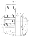
- Fig. 2
- eine etwas vergrößerte perspektivische Darstellung des gleichen Gurtstraffers in zusammengebautem Zustand in perspektivischer Ansicht von der entgegengesetzten Seite wie in Fig.1,
- Fig. 3
- eine mehr von der Seite des Zusatzantriebs her gesehene perspektivische Ansicht des gleichen, jedoch mit einem erfindungsgemäßen Fluid versehenen Gegenstandes, wobei jedoch zum Zwecke der Veranschaulichung die eine stirnseitige Abdeckung des Bandlaufraumes und die Rückzugsfederanordnung fortgelassen sind, und zwar in der Ausgangsposition unmittelbar nach dem Beginn der Zündung der pyrotechnischen Ladung,
- Fig. 4
- eine entsprechende Ansicht wie Fig. 3, jedoch während eines bereits in Gang befindlichen Gurtstraffvorganges,
- Fig. 5
- eine schematische Schnittansicht einer weiteren Ausführungsform eines Zusatzantriebes mit nur einem flexiblen Zugband, und
- Fig. 6
- eine schematische Schnittansicht analog Fig. 5 einer weiteren Ausführungsform mit zwei flexiblen Zugbändern.
Wenn der Beschleunigungssensors 43 (Fig. 3) eine unfallbedingte Beschleunigung am Fahrzeug feststellt, löst er über die Steuerleitung 42 die pyrotechnische Ladung 16 aus. Daraufhin beaufschlagt diese zunächst nicht, wie das in den Fig. 3 und 4 aus Veranschaulichungsgründen wiedergegeben ist, die Drehmomenterzeugungsvorrichtung 18, sondern nach Fig. 1 zunächst nur den Kolbenbereich 48' des Schiebers 48, so daß dieser aus der Ruheposition in die Einkupplungsposition verschoben wird und dabei die Kupplungsscheibe 44 zu einer Drehbewegung mitnimmt.
- 11
- Halter
- 12
- Gurtaufwickelrolle
- 13
- Sicherheitsgurt
- 13'
- Drahtseil
- 14
- Rückzugsfederanordnung
- 14'
- Rückzugsfederanordnung
- 15
- Zusatzantrieb
- 16
- Druckquelle
- 17
- Druckraum
- 18
- Drehmomenterzeugungsvorrichtung
- 19
- Antriebswelle
- 20
- Kupplung
- 21
- Zugband
- 22
- Antriebsrolle
- 22'
- Hohlsektor
- 22"
- Hohlsektor
- 23
- Bandlaufraum
- 23'
- druckbeaufschlagter Teilraum
- 23"
- nicht-druckbeaufschlagter Teilraum
- 24
- Gehäuse
- 24'
- Anschlag
- 25
- Befestigungsstelle an der Antriebsrolle 22
- 26
- Befestigungsstelle am Gehäuse 24
- 27
- Verzweigungsleitung
- 27'
- Zuleitung
- 28
- Verzweigungsleitung
- 29
- Dichtwand
- 29'
- Dichtlippe
- 29''
- Fortsatz
- 29"'
- Gelenk
- 30
- Umfangswand
- 31
- Dichtlippe
- 32
- Dichtelement
- 37
- Entlüftungsbohrung
- 37'
- Entlüftungskanal
- 38
- Achse
- 39
- Gurtschloß
- 40
- Fahrzeugchassis
- 41
- Innenwelle
- 42
- Steuerleitung
- 43
- Beschleunigungssensor
- 44
- Kupplungsscheibe
- 45
- Eingriffsausnehmung
- 46
- Eingriffsnocken
- 47
- Stirnführungsscheibe
- 48
- Schieber
- 48'
- Kolbenbereich
- 48"
- Betätigungsstange
- 49
- Verschiebeausnehmung
- 50
- Haltenocken
- 51
- Stirnwand
- 52
- Stirnwand
- 53
- Deckel
- 54
- Bohrung
- 55
- Keilnocken
- 56
- Umfangsschlitze
- 57
- Gegennocken
- 58
- Kupplungsgehäuse
- 59
- Ventilwand
- 60
- Aufnahmehohlraum
- 61
- Druckkanal
- 62
- Anschlag
- 63
- fluidartig verteilte Festteilchen
- 63'
- Festteilchenkomponente
- 64
- Vorratstasche
Claims (10)
- Einen Gurtstraffer aufweisende Sicherheitsgurtanordnung in Kraftfahrzeugen mit einem am Fahrzeugchassis zu befestigenden Halter (11), an dem drehbar eine Gurtaufwickelrolle (12) mit einem darauf aufgewickelten Sicherheitsgurt (13), eine Rückzugsfederanordnung (14, 14'), mittels der der Sicherheitsgurt (13) ständig in Einziehrichtung leicht so vorgespannt ist, daß er nur locker am von ihm gesicherten Fahrzeuginsassen anliegt, einer Feststellanordnung, insbesondere zwischen Gurtaufwickelrolle (12) und Halter (11) oder Fahrzeugchassis, welche den Sicherheitsgurt (13) bei plötzlichem Anziehen und/oder einer unfallbedingten Beschleunigung gegen Ausziehen sperrt, und mit einem über eine Kupplung (20) an die Gurtaufwickelrolle (12) angeschlossenen Zusatzantrieb (15), welcher normalerweise durch die ausgerückte Kupplung (20) von der Gurtaufwickelrolle (12) antriebsmäßig getrennt ist, jedoch bei einer unfallbedingten Beschleunigung schlagartig aktiviert und über die dann eingerückte Kupplung (20) drehfest mit der Gurtaufwickelrolle (12) gekuppelt wird, um den Sicherheitsgurt (13), noch bevor der von ihm gesicherte Fahrzeuginsasse in den Sicherheitsgurt (13) hineinfällt, um ein solches Wegstück aufzurollen, daß der Sicherheitsgurt straff am Fahrzeuginsassen anliegt, wobei der Zusatzantrieb (15) vorzugsweise eine beim unfallbedingten Ansprechen eines Beschleunigungssensors auslösbare bzw. zündbare, insbesondere pyrotechnische Druckquelle (16), welche bei Auslösung in einem Druckraum (17) schlagartig einen hohen Druck aufbaut, eine von dem Druck im Druckraum (17) beaufschlagte Drehmomenterzeugungsvorrichtung (18) und eine an diese angeschlossene Antriebswelle (19) bzw. Antriebsrolle (22) aufweist, die über die Kupplung (20) drehfest mit der Gurtaufwickelrolle (12) verbindbar ist, wobei die Drehmomenterzeugungsvorrichtung (18) wenigstens ein flexibles Zugband (21), welches insbesondere aus Federstahl besteht, aufweist, das einerseits am Umfang der Antriebswelle (19) oder einer konzentrisch darauf angebrachten Antriebsrolle (22) an einer ersten Befestigungsstelle (25) befestigt und teilweise auf die Antriebswelle (19) bzw. die Antriebsrolle (22) aufgewickelt ist und andererseits an der Umfangswand (30) eines um die Antriebswelle (19) bzw. die Antriebsrolle (22) herum angeordneten, eine der Breite des Zugbandes (21) entsprechende Breite aufweisenden Bandlaufraumes (23) innerhalb eines Gehäuses (24) an einer zweiten Befestigungsstelle (26) befestigt ist, derart, daß sich das Zugband (21) - den Bandlaufraum (23) in zwei voneinander abgedichtete Teilräume (23', 23") unterteilend - durch den Bandlaufraum (23) erstreckt, und wobei der Teilraum (23'), der bei Druckbeaufschlagung eine Abwicklung des Zugbandes (21) von der sich drehenden Antriebswelle (19) bzw. Antriebsrolle (20) bewirkt, an den Druckraum (17) angeschlossen und der andere Teilraum (23") vorzugsweise entlüftet (37) ist, und wobei zur druckmäßigen Entkopplung der Teilräume (23',23") wenigstens eine sich zwischen dem Gehäuse (24) und dem Umfang der Antriebswelle (19) bzw. der konzentrisch darauf angebrachten Antriebsrolle (22) bzw. dem darauf aufgewickelten flexiblen Zugband (21) erstreckende Dichtwand (29) vorgesehen ist,
dadurch gekennzeichnet,
daß in dem druckbeaufschlagten Teilraum (23') und vorzugsweise auch in den Zuleitungen (27, 28) zum druckbeaufschlagten Teilraum (23') ein Fluid (63) mit abdichtenden Eigenschaften angeordnet ist und/oder bei Auslösung der Druckquelle (16) dort eingebracht wird, derart, daß zu etwaigen Undichtigkeiten zwischen dem Zugband (21) bzw. den Zugbändern (21) einerseits und dem Gehäuse (24) bzw. gehäusefesten Flächen (51, 52) andererseits und gegebenenfalls auch im Bereich der Zuleitungen (27, 28) strömende Fluid die betreffende Undichtigkeit zumindest verkleinert und vorzugsweise zumindest weitgehend beseitigt. - Sicherheitsgurtanordnung nach Anspruch 1, dadurch gekennzeichnet, daß das Fluid ein Pulver (63) ist, wobei insbesondere das Pulver (63) Talkum ist, und/oder daß die Körner des Pulvers (63) zumindest teilweise und vorzugsweise größtenteils etwas größer dimensioniert sind als die vorhandenen Undichtigkeiten.
- Sicherheitsgurtanordnung nach Anspruch 1, dadurch gekennzeichnet, daß das Fluid aus kurzen Fasern besteht, welche deutlich länger als die Dimensionen der vorhandenen Undichtigkeiten sind und vorzugsweise auch einen größeren Durchmesser haben als die vorhandenen Undichtigkeiten.
- Sicherheitsgurtanordnung nach Anspruch 1, dadurch gekennzeichnet, daß das Fluid aus Flocken besteht, die durch ein Fasergewirr gebildet sind.
- Sicherheitsgurtanordnung nach Anspruch 1, dadurch gekennzeichnet, daß das Fluid aus Kunststoffschnitzeln besteht.
- Sicherheitsgurtanordnung nach Anspruch 5, dadurch gekennzeichnet, daß die Kunststoffschnitzel folien- bzw. blattförmig ausgebildet sind.
- Sicherheitsgurtanordnung nach Anspruch 6, dadurch gekennzeichnet, daß die Kunststoffschnitzel in ihrer Flächenausdehnung Längendimensionen von 0,2 bis 1,0, insbesondere 0,3 bis 0,8 mm und insbesondere etwa 0,5 mm aufweisen.
- Sicherheitsgurtanordnung nach Anspruch 1, dadurch gekennzeichnet, daß das Fluid aus kleinen Kunststoffkügelchen besteht, welche vorzugsweise eine Dimensionierung von 0,05 mm bis 0,15 mm und insbesondere etwa 0,1 mm aufweisen.
- Sicherheitsgurtanordnung nach einem der vorhergehenden Ansprüche, dadurch gekennzeichnet, daß das Fluid (63) in oder an der Zuleitung (27) bzw. den Zuleitungen (27, 28) derart angeordnet ist, daß es bei einer Auslösung der Druckquelle (16) in den druckbeaufschlagten Teilraum (23') strömt, wobei insbesondere neben den Zuleitungen (27, 28) wenigstens eine Vorratstasche (64) für das Fluid vorgesehen ist und Anordnung und Ausbildung der Vorratstasche (64) derart sind, daß das durch die Zuleitung (27, 28) strömende Gas aus der Druckquelle (16) das in der bzw. den Taschen (64) befindliche Fluid mitnimmt oder das Fluid (63') in der Druckquelle, d.h. dem Gasgenerator (16) angeordnet ist oder das Fluid (63') lose in den Zuleitungen (27, 28) angeordnet ist.
- Sicherheitsgurtanordnung nach einem der vorhergehenden Ansprüche, dadurch gekennzeichnet, daß das abdichtende Fluid (63) bei Auslösung der Druckquelle (16) entsteht und im Abgas der ausgelösten Druckquelle (16) enthalten ist.
Applications Claiming Priority (2)
| Application Number | Priority Date | Filing Date | Title |
|---|---|---|---|
| DE19503023A DE19503023A1 (de) | 1995-01-31 | 1995-01-31 | Einen Gurtstraffer aufweisende Sicherheitsgurtanordnung in Kraftfahrzeugen |
| DE19503023 | 1995-03-31 |
Publications (3)
| Publication Number | Publication Date |
|---|---|
| EP0734923A2 EP0734923A2 (de) | 1996-10-02 |
| EP0734923A3 EP0734923A3 (de) | 1998-03-18 |
| EP0734923B1 true EP0734923B1 (de) | 2000-05-03 |
Family
ID=7752749
Family Applications (1)
| Application Number | Title | Priority Date | Filing Date |
|---|---|---|---|
| EP96101132A Expired - Lifetime EP0734923B1 (de) | 1995-01-31 | 1996-01-26 | Einen Gurtstraffer aufweisende Sicherheitsgurtanordnung in Kraftfahrzeugen |
Country Status (3)
| Country | Link |
|---|---|
| EP (1) | EP0734923B1 (de) |
| AT (1) | ATE192389T1 (de) |
| DE (2) | DE19503023A1 (de) |
Families Citing this family (1)
| Publication number | Priority date | Publication date | Assignee | Title |
|---|---|---|---|---|
| DE102008038685B4 (de) * | 2008-08-12 | 2010-11-25 | Autoliv Development Ab | Gurtstraffer mit einem bistabil ausgelegten Kupplungselement |
Family Cites Families (9)
| Publication number | Priority date | Publication date | Assignee | Title |
|---|---|---|---|---|
| GB335980A (en) * | 1929-07-05 | 1930-10-06 | Percival George Masters | Improved means for use in sealing punctures in the inner tubes of pneumatic tyres |
| DE1084407B (de) * | 1958-07-01 | 1960-06-30 | Us Rubber Co | Selbstdichtende Masse fuer schlauchlose Reifen |
| DE6945600U (de) * | 1969-11-25 | 1970-10-22 | Winkelmann Hans-Georg | Kraftfahrzeug- und fahrradreifen. |
| DE2208401A1 (de) * | 1972-02-23 | 1973-08-30 | Bbc Brown Boveri & Cie | Feuchtigkeitssichere achsdurchfuehrung durch eine wand eines gehaeuses |
| NL7408109A (nl) * | 1974-06-18 | 1975-12-22 | Philips Nv | Afdichting tussen relatief roteerbare elementen. |
| DE2814550C2 (de) * | 1978-04-04 | 1986-12-04 | TRW Repa GmbH, 7077 Alfdorf | Rückstrammer mit pyrotechnischem Treibsatz für Sicherheitsgurtwickelautomaten |
| JPS55119649A (en) * | 1979-03-09 | 1980-09-13 | Matsushita Electric Ind Co Ltd | Tape winding method |
| FI76192C (fi) * | 1987-02-11 | 1988-09-09 | Tampella Oy Ab | Arrangemang foer taetning av en kammare som innehaoller tryckmedium. |
| DE4225218A1 (de) * | 1992-07-30 | 1994-02-03 | Takata Europ Gmbh | Gurtstraffer bei Sicherheitsgurtanordnungen in Kraftfahrzeugen |
-
1995
- 1995-01-31 DE DE19503023A patent/DE19503023A1/de not_active Withdrawn
-
1996
- 1996-01-26 EP EP96101132A patent/EP0734923B1/de not_active Expired - Lifetime
- 1996-01-26 DE DE59605096T patent/DE59605096D1/de not_active Expired - Fee Related
- 1996-01-26 AT AT96101132T patent/ATE192389T1/de not_active IP Right Cessation
Also Published As
| Publication number | Publication date |
|---|---|
| EP0734923A2 (de) | 1996-10-02 |
| DE59605096D1 (de) | 2000-06-08 |
| EP0734923A3 (de) | 1998-03-18 |
| ATE192389T1 (de) | 2000-05-15 |
| DE19503023A1 (de) | 1996-08-01 |
Similar Documents
| Publication | Publication Date | Title |
|---|---|---|
| DE19503150A1 (de) | Einen Gurtstraffer aufweisende Sicherheitsgurtanordnung in Kraftfahrzeugen | |
| DE4432594A1 (de) | Gurtstraffer bei Sicherheitsgurtanordnungen in Kraftfahrzeugen | |
| DE2510514C3 (de) | Aufwickelvorrichtung für Sicherheitsgurte mit pyrotechnisch angetriebener Schnelldreheinrichtung | |
| DE60105351T2 (de) | Sicherheitsgurtroller | |
| EP0093237B1 (de) | Aufwickelvorrichtung für Sicherheitsgurte in Fahrzeugen | |
| DE3215928C2 (de) | Aufwickelvorrichtung für Sicherheitsgurte | |
| EP0581288B1 (de) | Gurtstraffer bei Sicherheitsgurtanordnungen in Kraftfahrzeugen | |
| EP0808752B1 (de) | Gurtstraffer für ein Fahrzeuginsassen-Rückhaltesystem | |
| DE2300119A1 (de) | Anlage mit sicherheitsgurt fuer insassen von fahrzeugen, insbesondere kraftfahrzeugen | |
| DE60115579T2 (de) | Weich-Start-Betätigungskolben | |
| DE2421400C2 (de) | Rotationskraftelement | |
| DE10010379B4 (de) | Sicherheitsgurtsystem | |
| EP0529501A1 (de) | Rückstrammervorrichtung zum Straffen eines Sicherheitsgurtes in einem Kraftfahrzeug | |
| DE4444775A1 (de) | Gurtstraffer bei Sicherheitsgurtanordnungen in Kraftfahrzeugen | |
| DE69702438T2 (de) | Vorspannungsvorrichtung für sicherheitsgurte | |
| DE4000313C2 (de) | ||
| EP0734923A2 (de) | Einen Gurtstraffer aufweisende Sicherheitsgurtanordnung in Kraftfahrzeugen | |
| EP0875428B1 (de) | Gurtstraffer bei Sicherheitsgurtanordnungen in Kraftfahrzeugen | |
| DE10066249B4 (de) | Sicherheitsgurtsystem | |
| EP0635407B1 (de) | Sicherheitsgurtanordnung für Kraftfahrzeuge mit Straffervorrichtung | |
| DE4305596A1 (de) | Aufwickelvorrichtung für einen Sicherheitsgurt in Fahrzeugen | |
| DE102017221028B4 (de) | Gurtstraffer mit einem massekörperantrieb | |
| DE19961109A1 (de) | Sicherheitsgurtvorrichtung für Kraftfahrzeuge | |
| DE4422980C2 (de) | Gurtstraffer | |
| DE4432593C2 (de) | Gurtstraffer bei Sicherheitsgurtanordnungen in Kraftfahrzeugen |
Legal Events
| Date | Code | Title | Description |
|---|---|---|---|
| PUAI | Public reference made under article 153(3) epc to a published international application that has entered the european phase |
Free format text: ORIGINAL CODE: 0009012 |
|
| AK | Designated contracting states |
Kind code of ref document: A2 Designated state(s): AT DE ES FR GB IT SE |
|
| PUAL | Search report despatched |
Free format text: ORIGINAL CODE: 0009013 |
|
| AK | Designated contracting states |
Kind code of ref document: A3 Designated state(s): AT DE ES FR GB IT SE |
|
| 17P | Request for examination filed |
Effective date: 19980422 |
|
| GRAG | Despatch of communication of intention to grant |
Free format text: ORIGINAL CODE: EPIDOS AGRA |
|
| 17Q | First examination report despatched |
Effective date: 19990720 |
|
| GRAG | Despatch of communication of intention to grant |
Free format text: ORIGINAL CODE: EPIDOS AGRA |
|
| GRAH | Despatch of communication of intention to grant a patent |
Free format text: ORIGINAL CODE: EPIDOS IGRA |
|
| GRAH | Despatch of communication of intention to grant a patent |
Free format text: ORIGINAL CODE: EPIDOS IGRA |
|
| GRAA | (expected) grant |
Free format text: ORIGINAL CODE: 0009210 |
|
| AK | Designated contracting states |
Kind code of ref document: B1 Designated state(s): AT DE ES FR GB IT SE |
|
| PG25 | Lapsed in a contracting state [announced via postgrant information from national office to epo] |
Ref country code: IT Free format text: LAPSE BECAUSE OF FAILURE TO SUBMIT A TRANSLATION OF THE DESCRIPTION OR TO PAY THE FEE WITHIN THE PRE;WARNING: LAPSES OF ITALIAN PATENTS WITH EFFECTIVE DATE BEFORE 2007 MAY HAVE OCCURRED AT ANY TIME BEFORE 2007. THE CORRECT EFFECTIVE DATE MAY BE DIFFERENT FROM THE ONE RECORDED.SCRIBED TIME-LIMIT Effective date: 20000503 Ref country code: FR Free format text: LAPSE BECAUSE OF FAILURE TO SUBMIT A TRANSLATION OF THE DESCRIPTION OR TO PAY THE FEE WITHIN THE PRESCRIBED TIME-LIMIT Effective date: 20000503 Ref country code: ES Free format text: THE PATENT HAS BEEN ANNULLED BY A DECISION OF A NATIONAL AUTHORITY Effective date: 20000503 |
|
| REF | Corresponds to: |
Ref document number: 192389 Country of ref document: AT Date of ref document: 20000515 Kind code of ref document: T |
|
| REF | Corresponds to: |
Ref document number: 59605096 Country of ref document: DE Date of ref document: 20000608 |
|
| PG25 | Lapsed in a contracting state [announced via postgrant information from national office to epo] |
Ref country code: SE Free format text: LAPSE BECAUSE OF FAILURE TO SUBMIT A TRANSLATION OF THE DESCRIPTION OR TO PAY THE FEE WITHIN THE PRESCRIBED TIME-LIMIT Effective date: 20000803 |
|
| GBT | Gb: translation of ep patent filed (gb section 77(6)(a)/1977) |
Effective date: 20000717 |
|
| EN | Fr: translation not filed | ||
| PG25 | Lapsed in a contracting state [announced via postgrant information from national office to epo] |
Ref country code: AT Free format text: LAPSE BECAUSE OF NON-PAYMENT OF DUE FEES Effective date: 20010126 |
|
| PLBE | No opposition filed within time limit |
Free format text: ORIGINAL CODE: 0009261 |
|
| STAA | Information on the status of an ep patent application or granted ep patent |
Free format text: STATUS: NO OPPOSITION FILED WITHIN TIME LIMIT |
|
| 26N | No opposition filed | ||
| REG | Reference to a national code |
Ref country code: GB Ref legal event code: IF02 |
|
| PGFP | Annual fee paid to national office [announced via postgrant information from national office to epo] |
Ref country code: GB Payment date: 20080123 Year of fee payment: 13 Ref country code: DE Payment date: 20080124 Year of fee payment: 13 |
|
| GBPC | Gb: european patent ceased through non-payment of renewal fee |
Effective date: 20090126 |
|
| PG25 | Lapsed in a contracting state [announced via postgrant information from national office to epo] |
Ref country code: DE Free format text: LAPSE BECAUSE OF NON-PAYMENT OF DUE FEES Effective date: 20090801 |
|
| PG25 | Lapsed in a contracting state [announced via postgrant information from national office to epo] |
Ref country code: GB Free format text: LAPSE BECAUSE OF NON-PAYMENT OF DUE FEES Effective date: 20090126 |