EP0734784A2 - Elliptischen Schwingungsgerät - Google Patents
Elliptischen Schwingungsgerät Download PDFInfo
- Publication number
- EP0734784A2 EP0734784A2 EP96302152A EP96302152A EP0734784A2 EP 0734784 A2 EP0734784 A2 EP 0734784A2 EP 96302152 A EP96302152 A EP 96302152A EP 96302152 A EP96302152 A EP 96302152A EP 0734784 A2 EP0734784 A2 EP 0734784A2
- Authority
- EP
- European Patent Office
- Prior art keywords
- vibratory
- vibrational
- output
- detecting means
- controller
- Prior art date
- Legal status (The legal status is an assumption and is not a legal conclusion. Google has not performed a legal analysis and makes no representation as to the accuracy of the status listed.)
- Granted
Links
Images


Classifications
-
- B—PERFORMING OPERATIONS; TRANSPORTING
- B06—GENERATING OR TRANSMITTING MECHANICAL VIBRATIONS IN GENERAL
- B06B—METHODS OR APPARATUS FOR GENERATING OR TRANSMITTING MECHANICAL VIBRATIONS OF INFRASONIC, SONIC, OR ULTRASONIC FREQUENCY, e.g. FOR PERFORMING MECHANICAL WORK IN GENERAL
- B06B1/00—Methods or apparatus for generating mechanical vibrations of infrasonic, sonic, or ultrasonic frequency
- B06B1/02—Methods or apparatus for generating mechanical vibrations of infrasonic, sonic, or ultrasonic frequency making use of electrical energy
- B06B1/08—Methods or apparatus for generating mechanical vibrations of infrasonic, sonic, or ultrasonic frequency making use of electrical energy operating with magnetostriction
-
- B—PERFORMING OPERATIONS; TRANSPORTING
- B06—GENERATING OR TRANSMITTING MECHANICAL VIBRATIONS IN GENERAL
- B06B—METHODS OR APPARATUS FOR GENERATING OR TRANSMITTING MECHANICAL VIBRATIONS OF INFRASONIC, SONIC, OR ULTRASONIC FREQUENCY, e.g. FOR PERFORMING MECHANICAL WORK IN GENERAL
- B06B1/00—Methods or apparatus for generating mechanical vibrations of infrasonic, sonic, or ultrasonic frequency
- B06B1/02—Methods or apparatus for generating mechanical vibrations of infrasonic, sonic, or ultrasonic frequency making use of electrical energy
- B06B1/0207—Driving circuits
- B06B1/0223—Driving circuits for generating signals continuous in time
- B06B1/0238—Driving circuits for generating signals continuous in time of a single frequency, e.g. a sine-wave
- B06B1/0246—Driving circuits for generating signals continuous in time of a single frequency, e.g. a sine-wave with a feedback signal
-
- B—PERFORMING OPERATIONS; TRANSPORTING
- B06—GENERATING OR TRANSMITTING MECHANICAL VIBRATIONS IN GENERAL
- B06B—METHODS OR APPARATUS FOR GENERATING OR TRANSMITTING MECHANICAL VIBRATIONS OF INFRASONIC, SONIC, OR ULTRASONIC FREQUENCY, e.g. FOR PERFORMING MECHANICAL WORK IN GENERAL
- B06B3/00—Methods or apparatus specially adapted for transmitting mechanical vibrations of infrasonic, sonic, or ultrasonic frequency
-
- B—PERFORMING OPERATIONS; TRANSPORTING
- B06—GENERATING OR TRANSMITTING MECHANICAL VIBRATIONS IN GENERAL
- B06B—METHODS OR APPARATUS FOR GENERATING OR TRANSMITTING MECHANICAL VIBRATIONS OF INFRASONIC, SONIC, OR ULTRASONIC FREQUENCY, e.g. FOR PERFORMING MECHANICAL WORK IN GENERAL
- B06B2201/00—Indexing scheme associated with B06B1/0207 for details covered by B06B1/0207 but not provided for in any of its subgroups
- B06B2201/50—Application to a particular transducer type
- B06B2201/52—Electrodynamic transducer
- B06B2201/53—Electrodynamic transducer with vibrating magnet or coil
-
- B—PERFORMING OPERATIONS; TRANSPORTING
- B06—GENERATING OR TRANSMITTING MECHANICAL VIBRATIONS IN GENERAL
- B06B—METHODS OR APPARATUS FOR GENERATING OR TRANSMITTING MECHANICAL VIBRATIONS OF INFRASONIC, SONIC, OR ULTRASONIC FREQUENCY, e.g. FOR PERFORMING MECHANICAL WORK IN GENERAL
- B06B2201/00—Indexing scheme associated with B06B1/0207 for details covered by B06B1/0207 but not provided for in any of its subgroups
- B06B2201/70—Specific application
Definitions
- This invention relates to an elliptical vibratory apparatus which may be used, for example, for handling component parts such as bolts, nuts, electronic components such as transistors, or the like.
- a previously-proposed elliptical vibration parts-feeder is generally denoted by a reference numeral 1 and is provided with a bowl 2 having a spiral track formed in the wall of the bowl 2.
- a wiper constituting one of parts-orientating means is arranged at a suitable position of the down-stream side of the spiral track. The detail of the wiper is well-known and so is not shown.
- a flat plate is bent to form the wiper. The distance between the lower end of the flat plate and the track is larger than the thickness of a part to be handled in the bowl 2, but is smaller than twice the thickness.
- a posture-holding means is arranged at a discharge end portion of the spiral track. The parts having a predetermined posture are supplied through the posture holding means into a (not-shown) linear vibratory feeder as a next step.
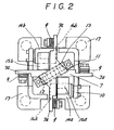
- the bowl 2 is fixed on an upper movable frame 7 as shown in Fig. 2.
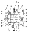
- a similarly cross-shaped lower movable frame 8 as clearly shown in Fig. 3 is combined with four sets of vertical leaf springs 9 with the upper movable frame 7.
- Upper ends of the leaf spring 9 are fixed to the end portions 7a of the upper movable frame 7.
- the lower ends of leaf springs 9 are fixed to the end portions 8a of the lower movable frame 8.
- the end portions 7a and 8a are in alignment with each other in the vertical direction.
- a vertical drive electro-magnet 11 is fixed at the central part of a stationary frame 10, facing to a central portion of the upper movable frame 7.
- a vertical movable core 13 is fixed to the lower side of the upper movable frame 7, facing to the vertical drive electro-magnet 11.
- a pair of horizontal drive electro-magnets 14a and 14b are fixed to side wall portions of the stationary frame 10 at both sides of the vertical drive electro-magnet 11.
- Electro-magnetic coils 15a and 15b are wound on the electro-magnet 14a and 14b.
- Horizontal movable cores 16a and 16b are fixed to the lower side of the upper movable frame 7, facing to the horizontal drive electro-magnets 14a and 14b, respectively.
- leg portions 17 are formed integrally with the stationary frame 10.
- the stationary frame 10 is supported through the leg portions 17 and vibration-absorbing rubbers 18 on the flour.
- Spring fixing portions 17a are formed integrally with the leg portions 17 as shown in Fig.3.
- Leaf springs 19 are fixed to the spring fixing portions 17a as shown in the manner in Fig.3. Both ends of the leaf springs 19 for the vertical drive are fixed to the spring fixing portions 17a by bolts B.
- the leaf springs 19 consist of two leaf spring elements which are superimposed through spacers 20 on each other.
- the central parts of the leaf springs 19 are fixed to the lower movable frame 8 by bolts B'.
- the horizontal drive electro-magnets 14a, 14b correspond to a first vibratory exciter for generating a horizontal exciting force.
- a first vibratory system to be driven by the horizontal electro-magnets 14a, 14b consists of the bowl 2, the leaf springs 9, the movable cores 16a and 16b, etc..
- the electro-magnet 11 correspond to a second vibratory exciter for generating a vertical exciting force. It consists of the bowl 2, the leaf springs 19,movable core 13, etc..
- the bowl 2 is vibrated at the resonant frequency or nearly at the frequency f 0 in the horizontal direction.
- the resonant frequency f 1 of the second (vertical) vibratory system in the vertical direction is usually higher by a few percentages than the horizontal resonant frequency f 0 .
- the phase difference between the force and vibrational displacement is equal to 90 degrees in the horizontal direction. That is clear from the vibration technology.
- the bowl 2 is vibrated at a different phase difference in the vertical direction.
- the bowl 2 is elliptically vibrated by the phase differences.
- the optimum phase difference between the vibrational displacement in the vertical and horizontal directions is theoretically equal to 60 degrees.
- the parts to be handled can be transported at the maximum transport speed on the track of the bowl 2.
- the phase difference is set to 90 degrees between the horizontal and vertical exciting forces.
- the resonant frequency in the vertical direction is equal to f 1 and so the vertical vibration occurs behind the vertical vibration force by the phase of 150 degrees.
- an elliptical vibratory apparatus comprising:
- an elliptical vibratory apparatus comprising:
- an elliptical vibratory apparatus comprising ;
- an elliptical vibratory apparatus comprising:
- an elliptical vibratory apparatus comprising:
- an elliptical vibratory apparatus comprising:
- an elliptical vibratory apparatus comprising:
- an elliptical vibratory apparatus comprising:
- an elliptical vibratory apparatus comprising:
- an elliptical vibratory apparatus comprising;
- an elliptical vibratory apparatus comprising;
- an elliptical vibratory apparatus comprising;
- an elliptical vibratory apparatus comprising;
- an elliptical vibratory system comprising;
- Fig.1 is a cross-sectional view of a vibratory Parts-feeder of the Prior Art.
- Fig.2 is a plan view, taken along the line II- II in Fig.1
- Fig.3 is a bottom view of the above Prior Art.
- Fig.4 is a chart for explaining the operation of the Prior Art.
- Fig.5 is a block diagram of an elliptical vibratory apparatus according to a first embodiment of this invention.
- Fig.6 is a block diagram of the details of the first embodiment.
- Fig.7 is a block diagram of an elliptical vibratory apparatus according to a second of embodiment of this embodiment.
- Fig.8 is a block diagram of the detail of the second embodiment.
- Fig.9 is a block diagram of an elliptical vibratory apparatus according to a third embodiment of this invention.
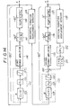
- Fig.10 is a block diagram of an elliptical vibratory apparatus according to fourth embodiment of this invention.
- Fig.11 is a block diagram of the detail of the fourth embodiment.
- Fig.12 is a block diagram of an important part of the fourth embodiment.
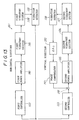
- Fig.13 is a block diagram of an elliptical vibratory apparatus according to a fifth embodiment of this invention.
- Fig.14 is a block diagram of the detail of the fifth embodiment.
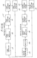
- Fig.15 is a block diagram of an elliptical vibratory apparatus according to a sixth embodiment of this invention.
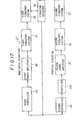
- Fig.16 is block diagram of an elliptical vibratory apparatus according to a seventh embodiment of this invention.
- Fig.17 is a block diagram of an elliptical vibratory apparatus according to an eighth embodiment of this invention.
- Fig.18 is a block diagram of an elliptical vibratory apparatus according to a ninth embodiment of this invention.
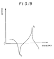
- Fig.19 is a chart for explaining operation of the ninth embodiments.
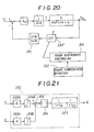
- Fig.20 is a block diagram of an important part of an elliptical vibratory apparatus according to a tenth embodiment of this invention.
- Fig.21 is a block diagram of the details of the tenth embodiment.
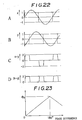
- Fig.22 are charts for explaining the operation of the tenth embodiment, A and B, wave forms of the horizontal and vertical vibration signals. C and D, wave forms rectified from the waves shown in A and B.
- Fig.23 is a chart for explaining the operation of the tenth embodiment.
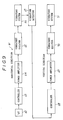
- Fig.5 shows an elliptical vibratory apparatus according to a first embodiment of this invention. It is generally denoted by a reference numeral 31.
- a vibration displacement of a horizontal vibratory system or a first vibratory system 32 is detected by a first vibration detector 33 and an output terminal of the first vibration detector 33 is connected to a vertical vibratory system 37 through a vertical or second controller 34, a second power amplifier 35 and a second (vertical) vibration exciter 36.
- a vibratory displacement in the vertical direction is detected by a second vibration detector 38 and it is supplied to a horizontal (first) controller 39 and then through a first power amplifier 40 and horizontal (first) vibration exciter 41 to the horizontal vibratory system 32.
- the output of the first vibration detector 33 is supplied directly to the second controller 34, while the output of the horizontal (second) vibration detector 38 is negatively fed-back to the first controller 39.
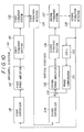
- Fig.6 shows the detail of the first embodiment. Parts which correspond to those in Fig.5, are denoted by the same reference numerals.
- the first controller 39 consists of a first phase shifter 42, a first high gain amplifier 43 and a first limiter for adjustment of an amplitude, (saturation element) 44.
- the output of the first controller 39 is supplied to the power amplifier 40, the amplified output is supplied to an electro-magnet 41 as the first vibratory exciter 41.
- the phase difference between the current and force is equal to an angle corresponding to a lag element of 1/(s+a 1 ), in the electro-magnet 41.
- the first vibratory system is vibrated by the output of the electro-magnet 41.
- the vibrational displacement in the horizontal direction is detected by the horizontal vibration detector 33 and the detected output is supplied to the second controller 34.
- It consists of a second phase shifter 45, a second high gain amplifier 46 and a second limiter for adjustment of the amplitude (saturation limiter 47) as in the first controller 39.
- the output of the second controller 34 is supplied to the power amplifier 35 and the amplified output is supplied to a vertical electro-magnet 36 as the second vibration exciter. It has a lag element of 1/(s+a 2 ).
- the phase lag of 90 degrees occurs in the same manner as the first vibration exciter or horizontal electro-magnet 41.
- the vertical vibratory system 37 is vibrated by the electro-magnet 36.
- the vibratory displacement of the vibratory system 37 is detected by the vibration detector 38 and the output is supplied to the first controller 39 as a negative feedback signal.
- one of the vibratory systems 32 and 37 is vibrated at the resonant frequency and another of them is vibrated at a frequency distant from the resonant frequency.
- the phase difference between the force and the displacement is equal to 90 degrees in the resonant vibration and the phase difference is nearly equal to zero in the vertical vibration system which is vibrated at the frequency distant from the resonant frequency.
- the electro-magnets 36 and 41 as the vibration exciters have the phase lag of 90 degrees.
- the advance phase ⁇ is equal to 60 degrees in the first phase shifter 42 according to this embodiment.
- the advance phase ⁇ is equal to 30 degrees in the second phase shifter 45.
- a DC power source is connected through electric switches to the power amplifiers 35 and 40. By turning on the electric switches, the power amplifiers 35 and 40 are put into the operative condition.
- the output of the vertical vibration detector 38 is negatively fed-back to the first controller 39.
- the input side of the first controller 39 is cut off from the output side of the vertical displacement detector 38, there is the phase difference of 180 degrees. Accordingly the vibratory systems can be self-excitedly vibrated.
- the horizontal vibratory system can be vibrated at the resonant frequency.
- the horizontal vibrational displacement is detected by the vibration detector 33 and the detecting output is supplied to the second controller 34 and is amplified by the second amplifier 35.
- the amplified output is supplied into the vertical electro-magnet 36. Accordingly, the vertical vibratory system 37 is self-excitedly vibrated, however the vibration frequency is distant from the horizontal resonant frequency by a few percentage. Since the horizontal vibratory system 32 is vibrated at the resonant frequency, the phase difference between the force and the displacement is maintained at 90 degrees. Further, the phase lag of the electro-magnet 41 is maintained at 90 degrees. The phase difference between the vibrations in the horizontal direction and vertical direction is maintained stably at the angle of 60 degrees. Accordingly, the bowl can be elliptically vibrated under the optimum condition. The parts to be handled, can be transported along the spiral track at the maximum transport speed in the bowl.
- the horizontal vibratory system can be self-excitedly oscillated or vibrated at the resonant frequency.
- the phase difference between the force and displacement is at the angle of 90 degrees.
- the phase difference varies much from 90 degrees. According to this embodiment, the change is little. Accordingly, the optimum condition can be stably maintained.
- amplitude controllers receiving the output of the horizontal vibration displacement detector 33 and the output of the vertical vibration detector 38 are connected to the limiters 44 and 47.
- the not-shown amplitude controllers include comparators, respectively. Predetermined amplitude voltages are applied to one input terminals of the comparator, and the outputs of the vibrational displacement detectors 33 and 38 are connected to other input terminals of the comparators. In accordance with the difference, the amplitude adjustment limiters 44 and 47 are automatically adjusted. Accordingly, the amplitudes in the horizontal and vertical directions can be maintained at constants respectively. As the result, an elliptical vibration having constant longer axis and shorter axis can be imparted to the bowl.
- Fig.7 and Fig 8 show an elliptical vibratory apparatus according to a second embodiment of this invention. It is generally denoted by a reference numeral 51. Parts which correspond to those in the above embodiment, are denoted by the same reference numerals, the description of which will be omitted.
- a closed loop is formed only in the horizontal vibratory system.
- the output of the horizontal vibrational detector 33 is negatively fed-back to the first controller 52 and is also supplied to the second (vertical) controller 53.
- Fig.8 shows the detail of the elliptical vibratory apparatus 51 according to this embodiment.
- the above embodiment and this embodiment are different from each other in the controllers 52 and 53.
- the controllers 52 and 53 consist of the phase shifters 55 and 58, high gain amplifiers 56 and 59 and amplitude adjustment limiters 57 and 60, respectably.
- a set phase difference is equal to zero in the first phase shifter 55, while another set phase difference ⁇ is equal to 30 degrees in the second phase shifter 58.
- the horizontal vibration detector 33 is cut off from the first controller 52, there is the phase difference of 180 degrees between the cut terminals.
- the phase difference between the output of the second vibratory system 37 and the input of the second controller 53 is equal to an angle of 60 degrees.
- the closed loop is formed only in the horizontal vibratory system.
- DC power sources are connected to the power amplifiers 35 and 40 through the not-shown electric switches.
- the horizontal vibratory system 32 is self-excitedly vibrated at the resonant frequency.
- the vertical vibratory system 37 is enforcedly vibrated.
- the phase difference between the force and the displacement in the horizontal vibratory system, in the resonant condition can be maintained at 90 degrees. Even when the drive frequency of the enforced vibration varies a little, the phase difference between the amplitude and the force change little. Accordingly, the phase difference can be maintained at 60 degrees between the vertical and horizontal vibrations. Accordingly, the optimum elliptical vibration can be obtained.
- Fig.9 shows an elliptical vibratory apparatus according to a third embodiment of this invention. It is generally denoted by a reference numeral 61.
- An output of a variable frequency power source 62 is supplied to a first controller 63.
- Output is amplified by a first power amplifier 64 and the amplified output is supplied to an electro-magnet 65 as an electric-vibratory exciter.
- a horizontal vibratory system 66 is vibrated in the same manner as in the above embodiments.
- the horizontal vibrational displacement of the vibratory system 66 is detected by a vibration detector 67 and the detected output is supplied to a second controller 68 for the vertical vibration.
- the controlled output is supplied through a second power amplifier 69 to an electro-magnet 70 as a vibratory exciter.
- a second vibratory system 71 is vibrated.
- the shift phase angle in the second controller 68 is equal to 60 degrees. Accordingly, although the vibratory system 66 is vibrated at the resonant frequency by adjusting the variable frequency power source 62, the vibratory system 71 is vertically vibrated with a phase difference of 60 degree. Accordingly, when the variable frequency power source 62 is accurately adjusted, the horizontal vibratory system 66 is surely vibrated at the resonant frequency and the phase difference of 60 degrees can be securely maintained between vertical and horizontal vibratory systems 66 and 71. Thus, the optimum elliptical vibration can be obtained.
- the controllers 63 and 68 do not include any saturation elements in contrast to the first and second embodiments.
- the output of the vibration detector 67 is supplied to a not-shown amplitude controller and the output is compared with a predetermined amplitude in the not-shown amplitude controller.
- the comparison result is supplied to the controller 63 and so a closed loop for constant amplitude is formed.
- the horizontal amplitude can be constant.
- a vertical vibrational detecting means there is not provided a vertical vibrational detecting means, however it may be arranged for obtaining a predetermined amplitude in the vertical direction.
- Fig.10 shows an elliptical vibratory apparatus according to the fourth embodiment of this invention and it is generally denoted by a reference numeral 131.
- a vibrational displacement of a horizontal vibratory system 132 is detected by a vibration detector 133 and the output is supplied through a second controller 234, a comparator 200, a second power amplifier 135 and a second vibration exciter 136 to a second vertical vibratory system 137.
- a vibrational displacement of the vertical vibratory system 137 is detected by a vibration detector 138 and the output is supplied to a first horizontal controller 139 and further the controlled output is supplied through a first power amplifier 140 and a first vibratory exciter 141 to a horizontal (first) vibratory system 132.
- the output of the vibrational detector 133 is directly supplied to the second controller 234, while the output of the vibration detector 138 is negatively fed-back to the first controller 139.
- the output of the vertical vibrational detector 138 is supplied also to a gain ⁇ k 2 amplifier 202.
- the output is supplied through a phase compensator 201 to the comparator 200 as a negative signal.
- the output of the amplifier 202 is advanced by the phase lag in the phase compensator 201 which corresponds to the phase lag of the vibratory exciter 136.
- the ⁇ k 2 and the phase compensation of the phase compensator 201 will be hereafter in detail.
- Fig.11 shows a block diagram of this embodiment and parts which correspond to those in Fig.10, are denoted by the same reference numerals.
- the first controller 139 includes a first phase shifter 142, a first high gain amplifier 143 and a first amplitude adjusting limiter 144 which is the saturation element.
- the output of the first controller 139 is supplied to the first power amplifier 140.
- the amplified output is supplied to an electro-magnet 141 as the vibratory exciter.
- the horizontal vibratory system 132 is vibrated with the output of the electro-magnet 141.
- m represents a mass of bowl
- c 1 viscous coefficient k 1 a spring constant in the horizontal direction.
- the vibration displacement of the horizontal vibratory system 132 is detected by the vibration detector 133 and the output is supplied to the second controller 134.
- the second controller 134 includes the phase shifter 145, the high gain amplifier 146 and the amplitude adjustment limiter 147 which is the saturation element.
- the output is supplied to the comparator 200 and the comparison result is supplied to the power amplifier 135.
- the amplified output is supplied to the vertical electro-magnet 136. It corresponds to a lag element, 1/(s+a 2 ).
- the phase lag of 90 degrees occurs in the vertical electro-magnet 136.
- the vertical vibratory system 137 is vibrated with the output of the vertical electro-magnet 136.
- the vibrational displacement of the vertical vibratory system 137 is detected by the vibrational displacement detector 138 and the detected output 2 is negatively fed-back to the first controller 139.
- the output of the vertical vibrational displacement detector 138 is supplied also to the gain amplifier 202 having a gain ⁇ k 2 .
- the value of the gain ⁇ k 2 is so designed as to be larger by a few percentages than the spring constant ⁇ k 2 .
- the acceleration, dx 2 / dt 2 of the movable part M which is a bowl in the vibratory parts feeder, is obtained by dividing the force applied to the movable part M by m which is the mass of the movable part M and then, the Laplace transformer s is multiplied with the acceleration, dx 2 /dt 2 . Accordingly, the velocity "dx/dt" is obtained. The viscous coefficient c is multiplied with the value, dx/dt. Thus, a resisting force against the movable part M can be obtained. It is negatively fed-back to the movable part M.
- the Laplace transformer, 1/s is multiplied with the detected dx/dt and so a displacement, x is calculated.
- a spring constant k is multiplied with the displacement x.
- the resisting force kx by the spring force is negatively fed-back to the movable part M.
- the resonant frequency is proportional to k 2 /m 2 .
- the value k 2 is electrically converted.
- the gain ⁇ k 2 corresponds to the spring constant k 2 .
- the resonant frequency of the vertical vibration system 137 is electrically raised by a few percentages.
- the electro-magnet 136 makes the phase lag.
- the phase advance element of (s+a 2 )/(s+b 2 ) (b 2 >a 2 ) is connected to the circuit for compensating the phase lag of the electro-magnet 136 and it is negatively fed-back to the comparator 200.
- the vibratory systems 132 and 137 are self-excitedly oscillated and so the phase difference between the force and displacement is equal to 90 degrees.
- the force to the vertical vibratory system 138 lags by a predetermined phase angle behind the horizontal vibratory system 133.
- the phase lags of the electro-magnets 136 and 141 as the vibratory exciters are equal to 90 degrees.
- the phase is advanced by 60 degrees in the first phase shifter 142.
- the phase is advanced by 30 degrees in the second phase shifter 145.
- electric switches are connected to the power amplifiers 135 and 140. With the closing of the electric switches, the power amplifiers 135 and 140 are put into the operative condition. In the closed loop as shown in Fig.11, the output of the vibration detector 138 of the vertical vibratory system 137 is negatively fed-back to the first controller 139. Accordingly, when the closed loop is cut off, there is the phase difference of 180 degrees between both of the terminals. Thus, the horizontal and vertical vibratory systems 132 and 137 can be self-excitedly vibrated at the resonant frequency.
- the vibrational displacement of the horizontal vibratory system 132 is detected by the vibration detector 133 and the detected output is supplied through the second controller 134, the comparator 200, the power amplifier 135 to the vertical electro-magnet 136.
- the vertical vibratory system 137 is driven with the output of the vertical electro-magnet 136.
- the horizontal vibratory system 132 is self-excitedly oscillated at the resonant frequency. Accordingly, the phase difference between the force and displacement can be maintained at 90 degrees.
- the phase lag of the electro-magnet 141 is maintained at 90 degrees. Accordingly, the phase difference between the horizontal and vertical vibrations can be maintained at 60 degrees.
- the gain ⁇ k 2 of the amplifier 202 is equal to the valve higher than by few percentages the mechanical spring constant in the vertical vibratory systems 137.
- the output detected by the vibrational displacement detector 138 is amplified by the gain amplifier 202 and it is supplied through the phase compensator 201 to the comparator 200.
- the phase lag is compensated in the phase compensator 201, which corresponds to the phase lag of the vertical electro-magnet 136.
- the mechanical resonant frequency of the vertical vibratory system 137 is not changed, however, the electrical resonant frequency rises up by few percentages corresponding to ⁇ k 2 . Accordingly, even when the voltage of the power source fluctuates, and the viscous coefficient and spring constant of the vibratory system 137 change, by which the mechanical resonant frequency of vibratory system changes, the phase difference between the vertical and horizontal displacements does not change.
- the negative feedback loop is not provided as in the Prior Art, the phase difference between the force and the displacement is much shifted from the phase difference ⁇ /2, and so the set phase difference between the horizontal and vertical vibrations is shifted much from the set value of 60 degrees.
- the phase difference between the horizontal and vertical vibrations can be stably maintained at the angle of 60 degrees.
- the bowl can be always vibrated under the optimum condition.
- the parts can be transported along the spiral track of the bowl at the maximum transport speed.
- the horizontal vibratory system can be always vibrated at the resonant frequency.
- the phase difference can be maintained at 90 degrees between the force (current) and the displacement.
- the vertical vibratory system is vibrated at the same frequency as the horizontal vibratory system and the imaginary resonant frequency of the vertical vibratory system is so designed as to be higher by a few percentages than resonant frequency of the vertical vibratory system.
- both of the vertical and horizontal vibratory systems can be vibrated at the resonant frequency. Even when the power source fluctuates and load to the movable part varies to change the resonant frequency, the phase difference between the horizontal and vertical vibrations can be maintained at the optimum conditioned valve.
- amplifier controllers are connected to the amplitude adjustment limiters 144 and 147, and receive the outputs of the horizontal and vertical vibration detector 133 and 138, respectively. They include comparators. Predetermined amplitudes are supplied to one input terminals of the comparators and the outputs of the vibration detector 133 and 138 are supplied to another input terminals. With the differences between the outputs of the vibration detectors 133 and 138, and the predetermined amplitudes, the amplitude adjustment limiters 144 and 147 are automatically adjusted and so the amplitudes of the vertical and horizontal vibrations can be maintained at the predetermined amplitudes, respectively. Thus, the elliptical vibration having predetermined longer axis and shorter axis, can be imparted to the bowl.
- Fig.13 and Fig.14 show an elliptical vibratory apparatus according to a fifth embodiment of this invention. It is generally denoted by a reference numeral 151. Parts which correspond to those in the above embodiment, are denoted by the same reference numerals, the details of which will be omitted.
- a closed loop for self-excitation is formed only in the horizontal vibratory system.
- the output of the horizontal vibration displacement detector 133 is negatively fed-back to the first controller 152. And it is further supplied to the second or vertical controller 153.
- the output of the vibrational displacement detector 138 for detecting the displacement of vertical vibration is amplified by the amplifier 202 having the gain ⁇ k 2 for the above described purpose and the output is supplied through the phase shifter 201 to the comparator 200.
- Fig.14 shows the details of the second embodiment.
- the controllers 152 and 153 include phase shifters 155 and 158, high gain amplifiers 156 and 159, and amplitude-adjustment limiters 157 and 160.
- a phase difference ⁇ is set in the first phase shifter 155, and it is equal to 0°, while a phase difference ⁇ is set in the second phase shifter 158 and is equal to 30 degrees. Accordingly, when the output of the horizontal vibration detector 133 and the first controller 152 are cut off from each other, there is a phase difference of -180 degrees. Further, there is a phase difference of -60 degrees between the output of the second vibratory systems 137 and the input of the second controller 153.
- the horizontal vibratory system 132 is self-excitedly vibrated at the resonant frequency and the vertical vibratory system 137 can be also vibrated at the resonant frequency.
- the phase difference between the forces and the displacements both in the horizontal and vertical vibrational systems can be obtained to be 90 degrees. Even when the resonant frequency is shifted a little from the phase difference between the displacement and force in the vertical vibratory system, changes little by function of the gain amplifier 202. Thus, the phase difference can be obtained to be the angle of 60 degrees between the horizontal and vertical directions. Thus, the optimum elliptical vibrational condition can be obtained.
- Fig.15 shows an elliptical vibratory system according to a sixth embodiment of this invention. It is generally denoted by a reference numeral 61.
- An output of a variable frequency power source 162 is supplied to the first controller 163.
- An output of the first controller 163 is amplified by an power amplifier 164.
- the amplified output is supplied to an electro-magnet 165 as a vibratory exciter.
- the horizontal vibratory system 166 is excited by the output of the electro-magnet 165.
- the vibrational displacement of the horizontal vibratory system 166 is detected by a vibration detector 167 and the detected output is supplied to a second controller 168 for the vertical vibration.
- the controlled output is supplied to one input terminal of the comparator 200 and a negative feedback signal is supplied to another input terminal of the comparator 200.
- a closed loop is formed by a power amplifier 169, a vibratory exciter 170, a vertical vibratory system 171, a vibrational displacement detector 138 and the gain amplifier 202 and the phase compensator 201.
- the output of the phase shifter 201 is negatively fed-back to the comparator 200.
- the second vibratory system 171 is driven with the output of the vibratory exciter 171.
- the phase difference is set at the angle of 60 degree in the second controller 168.
- the phase difference between the horizontal and vertical vibrations can be maintained accurately at the angle of 60 degrees. If the variable frequency power source 162 is accurately adjusted, the phase difference is securely maintained at the angle of 60 degrees and so the optimum elliptical vibration can be obtained.
- the controllers 163 and 168 are not provided with any saturation element.
- a closed loop is formed for constant amplitude.
- the vertical vibratory system 171 is vibrated at the resonant frequency.
- the electrical or imaginary resonant frequency of the vertical vibratory system 171 is risen by a few percentage of the mechanical resonant frequency.
- the closed loop for that purpose consists of the amplifier 169, the vibration exciter 170, the vibration system 171, the detector 138, the gain ⁇ K 2 amplifier 202.
- Another closed loop is formed for constant amplitude.
- the vertical vibratory system 171 is resonantly vibrated also.
- the electrical or imaginary resonant frequency of the vertical system 171 is risen by a few percentages of the mechanical resonant frequency by the closed loop which consists of the amplifier 202, the phase shifter 201 etc.. Even when the load to the movable part and the voltage of the electric power source fluctuate, the phase difference are varied little.
- Fig.16 shows an elliptical vibratory system according to a seventh embodiment of this invention. It is denoted generally denoted by a reference numeral 31'. The parts which correspond to those in the above embodiments, are denoted by the same reference numerals, the details of which will be omitted.
- the characteristic equation of the prefilter 300 is represented by (m 2 s 2 + c 2 s + k 2 )/ (m 2 s 2 +c 2 s + k 2 + ⁇ k 2 ).
- (m 2 s 2 + c 2 s + k 2 ) is a characteristic equation of the vertical vibratory system. This characteristic equation represents a notch component filter for cutting the resonant frequency f 0 as shown Fig.19.
- the spring constant consists of a mechanical constant k 2 and an imaginary spring constant ⁇ k 2 in the other characteristic equation. Accordingly, the imaginary resonant frequency f 1 is higher than the mechanical resonant frequency, by ⁇ k 2 .
- the prefilter 300 functions also a band pass filter for passing through the waves of the frequency higher by few percentages of the mechanical resonant frequency f 0 .
- the prefilter 200 consists of the notch filter for cutting the mechanical resonant frequency and the band-pass filter for passing through the frequency which is higher by few percentages than the mechanical resonant frequency.
- the vertical vibrational displacement instruction is given by the characteristic equation, (m 2 s 2 + c 2 s + k 2 ).
- the vertical vibratory system is vibrated at the resonant frequency, however, when the mechanical resonant frequency is varied, for example, with the change of the load to the bowl, the phase difference is varied much.
- the electrical resonant frequency is so designed as to be higher than the mechanical resonant frequency, as above described.
- the phase angles are set in the first and second phase controllers 142 and 145.
- the phase angle between the horizontal vibration displacement and the vertical vibrational displacement is maintained at the angle of 60 degrees.
- the optimum elliptical vibration can be obtained. Any other functions and effects of this embodiment can be the same as in above embodiments.
- Fig.17 shows an elliptical vibrational apparatus 51' according to an eighth embodiment of this invention. Parts which correspond to those in the above embodiments, are denoted by the same reference numerals, the detail of which will be omitted. Also in this embodiment, the closed loop including the gain amplifier 202 and the phase shifter 201 are omitted. Instead, the prefilter 300 is arranged also as in the seventh embodiment. The prefilter 300 of this embodiment has the similar function and effect as that of the seventh embodiment.
- Fig.18 shows an elliptical vibratory apparatus 61' according to a ninth embodiment of this invention. Parts which correspond to those in the above embodiments, are denoted by the same reference numerals, the detail of which will be omitted. Also in this embodiment, the closed loop including the gain amplifier 202 and the phase shifter 201 are omitted. Instead, the prefilter 300 as in the seventh and eighth embodiments is provided. The operation and the effects are the same as in the above embodiment. Accordingly, the description will be omitted.
- Fig.20 to Fig.23 show an elliptical vibratory apparatus according to a tenth embodiment of this invention. Parts which correspond to those in the above embodiments, are represented by the same reference numerals, the detail of description will be omitted.
- the gain ⁇ k of the amplifier 202' is adjusted with a phase difference of the vibrational displacement of the vertical vibratory system.
- a vibratory displacement signal x in the horizontal direction and another vibratory displacement signal y in the vertical direction are supplied to amplifiers 303a and 303b having gain K.
- the amplified outputs are supplied to limiters 304a and 304b having positive and negative saturation levels respectively.
- the amplified outputs are cut at predetermined levels in the limiters 303a and 303b.
- the obtained rectangular waves are compared with a comparator 305 and the comparison result is supplied to an absolute value circuit 306 and the output is supplied to a low-pass filter 307.
- the absolute value circuit 306 corresponds to a rectifying circuit.
- the low-pass filter 307 has the transfer factor of ⁇ 1/(1+T 1 s) ⁇ ⁇ 1/(1+T 2 s) ⁇ .
- the output is a phase difference output ⁇ .
- a phase difference between the horizontal vibrational displacement signal x and vertical vibrational displacement signal y is as shown in 22A and 22B. These signals are cut at the predetermined levels by the limiters 304a and 304b, and the substruction is effected between the horizontal vibrational displacement signal x and the vertical displacement signal y in the comparator 305.
- the comparison results are obtained as shown in Fig.22C.
- the output is supplied to the absolute value circuit 306. Accordingly, the wave shape as shown in Fig.22D can be obtained. Further, it is passed through the low-pass filter 307.
- a DC output in proportion to the difference between the horizontal and vertical vibratory displacement signals x and y can be obtained as the phase difference output ⁇ .
- phase difference The relationship between the phase difference and the detecting output ⁇ 0 is as shown in Fig.23. It changes linearly within the angle of the 180 degrees and it is at the maximum value at the 180 degrees. Hereafter, it decreased linearly with angles.
- Such output is supplied to a phase difference controller 301, and so the controller 301 is controlled in accordance with the phase difference output.
- the gain ⁇ k of the amplifier 202' can be adjusted with the phase difference output.
- the phase angle between the horizontal and vertical vibrational displacements can be adjusted to the optimum angle of 60 degrees.
- both the vertical vibratory system and the horizontal vertical system can be vibrational at the resonant frequency, even when anyone of the vibratory systems fluctuates with the change of the power source and the load to the movable parts.
- the phase difference can be securely and stably maintained at the angle of 60 degrees.
- the electro-magnet is used as the vibratory exciter. It has the phase lag of 90 degrees.
- phase difference 180 degrees in the negative feed-back loop.
- phase difference of the 60 degrees can be obtained between the horizontal and vertical vibration.
- the set phase difference angles are constant in the phase shifters 42 and 45 in the controller 39 and 34. Instead, they may be variable. A phase difference may be detected between outputs and/or inputs of any circuit blocks shown in the above embodiments, for adjusting the set phase difference of the phase shifters 42, 45.
- the optimum phase difference between the vertical and horizontal direction is equal to 60 degrees.
- the optimum phase difference may be somewhat varied in accordance with the magnitude of the longer axis of the elliptical vibrator. For example, it may be varied between the angles 45 degrees and 75 degrees. In this case, the angle ⁇ , ⁇ may be varied in accordance with the values of the optimum phase difference.
- first (horizontal) direction and the second (vertical) direction may be inverted.
Applications Claiming Priority (6)
| Application Number | Priority Date | Filing Date | Title |
|---|---|---|---|
| JP10046895 | 1995-03-31 | ||
| JP10046795 | 1995-03-31 | ||
| JP10046795A JP3161277B2 (ja) | 1995-03-31 | 1995-03-31 | 楕円振動装置 |
| JP100468/95 | 1995-03-31 | ||
| JP10046895A JP3531279B2 (ja) | 1995-03-31 | 1995-03-31 | 振動装置 |
| JP100467/95 | 1995-03-31 |
Publications (3)
| Publication Number | Publication Date |
|---|---|
| EP0734784A2 true EP0734784A2 (de) | 1996-10-02 |
| EP0734784A3 EP0734784A3 (de) | 1998-04-15 |
| EP0734784B1 EP0734784B1 (de) | 2001-11-14 |
Family
ID=26441486
Family Applications (1)
| Application Number | Title | Priority Date | Filing Date |
|---|---|---|---|
| EP96302152A Expired - Lifetime EP0734784B1 (de) | 1995-03-31 | 1996-03-28 | Elliptischen Schwingungsgerät |
Country Status (6)
| Country | Link |
|---|---|
| US (2) | US5804733A (de) |
| EP (1) | EP0734784B1 (de) |
| KR (1) | KR100392261B1 (de) |
| CN (1) | CN1075210C (de) |
| DE (1) | DE69616851T2 (de) |
| SG (1) | SG42367A1 (de) |
Families Citing this family (22)
| Publication number | Priority date | Publication date | Assignee | Title |
|---|---|---|---|---|
| US5948987A (en) * | 1996-06-20 | 1999-09-07 | Liu; Hong S. | Rotational shock fixture |
| JPH11106020A (ja) * | 1997-09-30 | 1999-04-20 | Shinko Electric Co Ltd | 振動パーツフィーダ |
| US6854585B2 (en) * | 2002-12-17 | 2005-02-15 | David Brooks | Multidirectional part transporter and sorter |
| WO2005087393A1 (en) * | 2004-03-18 | 2005-09-22 | Flexidrill Limited | Vibrational heads and assemblies and uses thereof |
| CN100395929C (zh) * | 2004-11-26 | 2008-06-18 | 上海电缆研究所 | 一种让架空线产生椭圆运动轨迹的方法和它的机构 |
| US7228957B1 (en) * | 2005-12-09 | 2007-06-12 | Tna Australia Pty Limited | Slip conveyor assembly |
| CA2744187C (en) * | 2008-11-21 | 2018-07-17 | Hadar Magali | Rebound-effector producing back and forth oscillating forces |
| CN101972856B (zh) * | 2010-09-16 | 2012-02-08 | 长春工业大学 | 一种非共振三维椭圆金刚石飞切光学自由曲面方法及专用装置 |
| CN102602689A (zh) * | 2012-03-20 | 2012-07-25 | 东莞市怡合达自动化科技有限公司 | 中大型振动底盘的顺逆兼容式结构 |
| US9377375B2 (en) * | 2012-05-16 | 2016-06-28 | Venturedyne, Ltd. | Repetitive shock vibration testing system and method |
| JP6153308B2 (ja) * | 2012-10-10 | 2017-06-28 | Ntn株式会社 | 振動式部品搬送装置 |
| CN105262377A (zh) * | 2015-10-28 | 2016-01-20 | 瑞声光电科技(常州)有限公司 | 多电机驱动系统及其驱动方法 |
| CH713047A1 (de) * | 2016-10-14 | 2018-04-30 | K Tron Tech Inc | Verfahren zur Regelung der Vibrationsbewegung eines Vibrationsförderers und einen Vibrationsförderer. |
| KR20230116077A (ko) * | 2016-12-07 | 2023-08-03 | 가부시키가이샤 무라타 세이사쿠쇼 | 전자부품의 진동 삽입 방법 및 장치 |
| US10974908B2 (en) * | 2017-09-12 | 2021-04-13 | Spirol International Corporation | Methods and systems for controlling a vibratory feeder |
| GB2572350B (en) * | 2018-03-27 | 2023-01-25 | Hitachi Rail Ltd | An electromechanical generator for converting mechanical vibrational energy into electrical energy |
| JP6901688B2 (ja) * | 2018-04-19 | 2021-07-14 | シンフォニアテクノロジー株式会社 | 振動系の制御装置およびワーク搬送装置 |
| US11414274B2 (en) * | 2018-07-16 | 2022-08-16 | Mitsuo FUKASE | Work-piece feeding assembly |
| US20220163374A1 (en) * | 2019-04-12 | 2022-05-26 | Satake Corporation | Sieving device |
| DE102020106350B4 (de) * | 2020-03-09 | 2021-09-16 | IMA-TEC GmbH | Fördergerät |
| CN111701833A (zh) * | 2020-06-22 | 2020-09-25 | 陕西师范大学 | 超磁致伸缩窗形椭圆复合振动换能器及换能方法 |
| CN114035626B (zh) * | 2021-11-12 | 2022-10-04 | 中国科学院长春光学精密机械与物理研究所 | 振动控制装置及其控制方法 |
Citations (5)
| Publication number | Priority date | Publication date | Assignee | Title |
|---|---|---|---|---|
| US4002270A (en) * | 1975-05-02 | 1977-01-11 | Cleveland Machine Controls, Inc. | Vibratory feeder system |
| US4395665A (en) * | 1981-06-09 | 1983-07-26 | The Arthur G. Russell Company, Incorporated | Control system for vibrating a member at its resonant frequency |
| WO1992022861A1 (en) * | 1991-06-15 | 1992-12-23 | Paul Allan Marriott | Improvements to vibrating materials handling and processing devices |
| US5205395A (en) * | 1991-06-10 | 1993-04-27 | Electro Scientific Industries, Inc. | Vibratory movement and manipulation apparatus and method |
| WO1993015850A1 (en) * | 1992-02-07 | 1993-08-19 | Valleylab, Inc. | Ultrasonic surgical apparatus |
Family Cites Families (7)
| Publication number | Priority date | Publication date | Assignee | Title |
|---|---|---|---|---|
| US3654804A (en) * | 1967-01-03 | 1972-04-11 | Chadwick Elect Inc H | Stabilization of multiple shaker systems |
| US4692649A (en) * | 1985-03-01 | 1987-09-08 | Canon Kabushiki Kaisha | Driving circuit of a vibration wave motor |
| JPH0798567B2 (ja) * | 1988-11-21 | 1995-10-25 | 神鋼電機株式会社 | 振動部品搬送機における部品詰り除去方法 |
| US5074403A (en) * | 1989-05-08 | 1991-12-24 | K-Tron Technologies, Inc. | Apparatus and method for two loop control of vibratory material feeders |
| EP0629568B1 (de) * | 1993-06-16 | 1997-12-10 | Ykk Corporation | Verfahren und Vorrichtung zum Steuern des Antriebs von selbst-erregten Vibrationsförderern |
| US5494151A (en) * | 1993-08-06 | 1996-02-27 | Shinko Electric Co., Ltd. | Vibratory parts-feeder apparatus |
| US5404995A (en) * | 1993-10-13 | 1995-04-11 | Graham; S. Neal | Vibratory parts feeder |
-
1996
- 1996-03-26 US US08/620,676 patent/US5804733A/en not_active Expired - Fee Related
- 1996-03-28 DE DE69616851T patent/DE69616851T2/de not_active Expired - Fee Related
- 1996-03-28 EP EP96302152A patent/EP0734784B1/de not_active Expired - Lifetime
- 1996-03-29 CN CN96104157A patent/CN1075210C/zh not_active Expired - Fee Related
- 1996-03-29 KR KR1019960009175A patent/KR100392261B1/ko not_active IP Right Cessation
- 1996-03-29 SG SG1996006750A patent/SG42367A1/en unknown
-
1998
- 1998-03-24 US US09/046,752 patent/US6044710A/en not_active Expired - Lifetime
Patent Citations (5)
| Publication number | Priority date | Publication date | Assignee | Title |
|---|---|---|---|---|
| US4002270A (en) * | 1975-05-02 | 1977-01-11 | Cleveland Machine Controls, Inc. | Vibratory feeder system |
| US4395665A (en) * | 1981-06-09 | 1983-07-26 | The Arthur G. Russell Company, Incorporated | Control system for vibrating a member at its resonant frequency |
| US5205395A (en) * | 1991-06-10 | 1993-04-27 | Electro Scientific Industries, Inc. | Vibratory movement and manipulation apparatus and method |
| WO1992022861A1 (en) * | 1991-06-15 | 1992-12-23 | Paul Allan Marriott | Improvements to vibrating materials handling and processing devices |
| WO1993015850A1 (en) * | 1992-02-07 | 1993-08-19 | Valleylab, Inc. | Ultrasonic surgical apparatus |
Also Published As
| Publication number | Publication date |
|---|---|
| CN1139207A (zh) | 1997-01-01 |
| EP0734784A3 (de) | 1998-04-15 |
| DE69616851D1 (de) | 2001-12-20 |
| SG42367A1 (en) | 1997-08-15 |
| EP0734784B1 (de) | 2001-11-14 |
| US6044710A (en) | 2000-04-04 |
| CN1075210C (zh) | 2001-11-21 |
| KR960033568A (ko) | 1996-10-22 |
| DE69616851T2 (de) | 2002-04-11 |
| KR100392261B1 (ko) | 2003-10-22 |
| US5804733A (en) | 1998-09-08 |
Similar Documents
| Publication | Publication Date | Title |
|---|---|---|
| US6044710A (en) | Elliptical vibratory apparatus | |
| EP0735448B1 (de) | Vibrationsgerät | |
| US4658172A (en) | Drive circuit for a vibration wave motor | |
| US5032753A (en) | Piezoelectric transducer and an ultrasonic motor using the piezoelectric transducer | |
| GB2124442A (en) | Ultrasonic transducer driving apparatus | |
| US4197478A (en) | Electronically tunable resonant accelerometer | |
| CN101790675B (zh) | 绝对位移检测方法和使用该方法的绝对位移传感器 | |
| US6753640B2 (en) | Piezoelectric driven type vibratory feeder | |
| US5127512A (en) | Method of operating a magnetically driven vibrating conveyor and apparatus for implementing the method | |
| US7183738B2 (en) | Motor control device | |
| EP0385409B1 (de) | Blattfördervorrichtung | |
| EP0216579A2 (de) | Steuerung von Vibrationserregung | |
| KR100376008B1 (ko) | 진동장치 | |
| JP3531279B2 (ja) | 振動装置 | |
| JP6820484B2 (ja) | 振動系の制御装置およびワーク搬送装置 | |
| JP3161277B2 (ja) | 楕円振動装置 | |
| SU1509841A1 (ru) | Регул тор дл виброзащитного устройства | |
| JP3752701B2 (ja) | 自励振動型振動制御装置 | |
| KR20190044488A (ko) | 진동계의 제어 장치 및 워크 반송 장치 | |
| JPH03256579A (ja) | 超音波モータ | |
| JPH1045232A (ja) | 楕円振動装置 | |
| KR0166055B1 (ko) | 자기적으로 지지된 이동부재의 변위 제어 장치 | |
| JPH10157827A (ja) | 楕円振動装置 | |
| Murray et al. | Electromagnetic moving armature actuators for active vibration control | |
| KR101330140B1 (ko) | 공진 수단의 구동 장치 및 방법 |
Legal Events
| Date | Code | Title | Description |
|---|---|---|---|
| PUAI | Public reference made under article 153(3) epc to a published international application that has entered the european phase |
Free format text: ORIGINAL CODE: 0009012 |
|
| AK | Designated contracting states |
Kind code of ref document: A2 Designated state(s): CH DE LI |
|
| PUAL | Search report despatched |
Free format text: ORIGINAL CODE: 0009013 |
|
| AK | Designated contracting states |
Kind code of ref document: A3 Designated state(s): CH DE LI |
|
| 17P | Request for examination filed |
Effective date: 19980908 |
|
| 17Q | First examination report despatched |
Effective date: 19990318 |
|
| GRAG | Despatch of communication of intention to grant |
Free format text: ORIGINAL CODE: EPIDOS AGRA |
|
| GRAG | Despatch of communication of intention to grant |
Free format text: ORIGINAL CODE: EPIDOS AGRA |
|
| GRAH | Despatch of communication of intention to grant a patent |
Free format text: ORIGINAL CODE: EPIDOS IGRA |
|
| GRAH | Despatch of communication of intention to grant a patent |
Free format text: ORIGINAL CODE: EPIDOS IGRA |
|
| GRAA | (expected) grant |
Free format text: ORIGINAL CODE: 0009210 |
|
| AK | Designated contracting states |
Kind code of ref document: B1 Designated state(s): CH DE LI |
|
| REG | Reference to a national code |
Ref country code: CH Ref legal event code: EP |
|
| REG | Reference to a national code |
Ref country code: CH Ref legal event code: NV Representative=s name: MICHELI & CIE INGENIEURS-CONSEILS |
|
| REF | Corresponds to: |
Ref document number: 69616851 Country of ref document: DE Date of ref document: 20011220 |
|
| PLBE | No opposition filed within time limit |
Free format text: ORIGINAL CODE: 0009261 |
|
| STAA | Information on the status of an ep patent application or granted ep patent |
Free format text: STATUS: NO OPPOSITION FILED WITHIN TIME LIMIT |
|
| 26N | No opposition filed | ||
| PGFP | Annual fee paid to national office [announced via postgrant information from national office to epo] |
Ref country code: CH Payment date: 20040329 Year of fee payment: 9 |
|
| PGFP | Annual fee paid to national office [announced via postgrant information from national office to epo] |
Ref country code: DE Payment date: 20040408 Year of fee payment: 9 |
|
| PG25 | Lapsed in a contracting state [announced via postgrant information from national office to epo] |
Ref country code: LI Free format text: LAPSE BECAUSE OF NON-PAYMENT OF DUE FEES Effective date: 20050331 Ref country code: CH Free format text: LAPSE BECAUSE OF NON-PAYMENT OF DUE FEES Effective date: 20050331 |
|
| PG25 | Lapsed in a contracting state [announced via postgrant information from national office to epo] |
Ref country code: DE Free format text: LAPSE BECAUSE OF NON-PAYMENT OF DUE FEES Effective date: 20051001 |
|
| REG | Reference to a national code |
Ref country code: CH Ref legal event code: PL |