EP0731318B1 - Baking oven - Google Patents
Baking oven Download PDFInfo
- Publication number
- EP0731318B1 EP0731318B1 EP19950103199 EP95103199A EP0731318B1 EP 0731318 B1 EP0731318 B1 EP 0731318B1 EP 19950103199 EP19950103199 EP 19950103199 EP 95103199 A EP95103199 A EP 95103199A EP 0731318 B1 EP0731318 B1 EP 0731318B1
- Authority
- EP
- European Patent Office
- Prior art keywords
- door
- baking oven
- air
- oven
- window
- Prior art date
- Legal status (The legal status is an assumption and is not a legal conclusion. Google has not performed a legal analysis and makes no representation as to the accuracy of the status listed.)
- Expired - Lifetime
Links
Images
Classifications
-
- F—MECHANICAL ENGINEERING; LIGHTING; HEATING; WEAPONS; BLASTING
- F24—HEATING; RANGES; VENTILATING
- F24C—DOMESTIC STOVES OR RANGES ; DETAILS OF DOMESTIC STOVES OR RANGES, OF GENERAL APPLICATION
- F24C15/00—Details
- F24C15/02—Doors specially adapted for stoves or ranges
- F24C15/04—Doors specially adapted for stoves or ranges with transparent panels
-
- F—MECHANICAL ENGINEERING; LIGHTING; HEATING; WEAPONS; BLASTING
- F24—HEATING; RANGES; VENTILATING
- F24C—DOMESTIC STOVES OR RANGES ; DETAILS OF DOMESTIC STOVES OR RANGES, OF GENERAL APPLICATION
- F24C15/00—Details
- F24C15/006—Arrangements for circulation of cooling air
Definitions
- the invention relates to an oven according to the Preamble of claim 1.
- ovens in particular with a device for pyrolytic Self-cleaning known (DE-A-25 45 531; DE-A-23 43 640), in which with a free air gap to one front door glass plate with a transparent interior one of several also transparent, but the Passage of heat radiation inhibiting glass plates or Glass panel composite existing window assembly within of the metallic door floor is arranged, in which Cavity between the window assembly and the front Glass plate through lower and upper air openings dissipating heat inside the oven door Air convection flow is effected.
- the subject of last mentioned document is for the pyrolytic Self-cleaning operation from outside the viewing area Aperture that can be moved into the viewing area provided through which in self-cleaning operation the air flow is directed and through which an additional Heat radiation to the outside should be prevented.
- Esp. due to the thermally insulating multiple glazing the viewing area remains within the window assembly relatively cool for a long time, while the rest Door areas e.g. warm the door edge area relatively quickly. It is usually unavoidable from the interior outgoing vapors or steam e.g. on the edge the door assembly into the interior of the oven door and on the coldest point in each case, i.e. in the viewing area e.g. condensed on the inner surface of the front glass pane.
- the invention has for its object an oven the type mentioned in the preamble of claim 1 to improve condensation in the see-through area the oven door can be at least largely avoided.
- the invention is based on one shown in the drawing Embodiment explained below.
- the oven muffle open on one side 3 can be closed by an oven door 8, which is essentially is formed from a large front Glass pane 9, which e.g.
- a transparent pane area forming a see-through window 10 has, while the glass sheet 9 outside this window is not transparent, e.g. with a Printing is provided.
- Carrier of this glass sheet 9 is a metallic door floor 11, formed by two step-shaped Sections 11.1 and 11.2 (see Fig. 2). With free Air distance to the front glass panel 9 is arranged a generally designated 12 window assembly 12 with in a composite frame 13 arranged glass panes 14, the one Form glass panes.
- a seal 16 e.g. a glass silk seal, the pyrolytically self-cleaning operation of the Oven instead of a rubber seal is required.
- metallic flow barrier 18 attached to the at least approximately to the inner surface of the front Glass pane 9 extends, preferably on this inner surface is supported in the peripheral region of the viewing window 10.
- This flow barrier 18 is formed by frame-like Compound, funnel-like in the embodiment air baffles inclined outwards. This will through a lower inlet opening 19 (Fig. 1) into the cavity of the floor 11 flowing in the direction of the arrow and through natural convection when the door assembly is heated air flowing upwards at least largely from the window 10 kept away, i.e. it flows around the thermal barrier 18 and is through an upper air outlet opening 20th derived into the open, favored by the injector effect of the forced air flow emanating from the cooling air blower 5.
Description
Die Erfindung bezieht sich auf einen Backofen gemäß dem Oberbegriff des Patentanspruches 1.The invention relates to an oven according to the Preamble of claim 1.
Es sind Backöfen insb. mit einer Einrichtung zur pyrolytischen Selbstreinigung bekannt (DE-A-25 45 531; DE-A-23 43 640), bei denen mit freiem Luftabstand zu einer frontseitigen Tür-Glasplatte mit einem transparenten Innenbereich eine aus mehreren ebenfalls transparenten, aber den Durchgang von Wärmestrahlen hemmenden Glasplatten oder Glasplattenverbund bestehenden Fensterbaugruppe innerhalb des metallischen Türbodens angeordnet ist, wobei in dem Hohlraum zwischen der Fensterbaugruppe und der frontseitigen Glasplatte durch untere und obere Luftöffnungen eine der Abführung von Wärme innerhalb der Ofentür dienende Luft-Konvektionsströmung bewirkt wird. Beim Gegenstand der zuletzt genannten Druckschrift ist für den pyrolytischen Selbstreinigungsbetrieb eine von außerhalb des Durchsichtbereiches bis in den Durchsichtbereich verschiebbare Blende vorgesehen, durch die hindurch bei Selbstreinigungsbetrieb die Luftströmung geleitet wird und durch die zusätzlich eine Wärmeabstrahlung nach außen verhindert werden soll. Insb. aufgrund der thermisch isolierenden Mehrfachverglasung innerhalb der Fensterbaugruppe bleibt der Durchsichtbereich längere Zeit relativ kühl, während sich die übrigen Türbereiche z.B. der Türrandbereich relativ schnell erwärmen. Es ist meist nicht zu verhindern, daß vom Innenraum der Ofenmuffel ausgehender Wrasen oder Dampf z.B. am Rand der Türbaugruppe in das Innere der Ofentür gelangt und an der jeweils kältesten Stelle, also im Durchsichtbereich z.B. an der Innenfläche der frontseitigen Glasscheibe kondensiert.There are ovens in particular with a device for pyrolytic Self-cleaning known (DE-A-25 45 531; DE-A-23 43 640), in which with a free air gap to one front door glass plate with a transparent interior one of several also transparent, but the Passage of heat radiation inhibiting glass plates or Glass panel composite existing window assembly within of the metallic door floor is arranged, in which Cavity between the window assembly and the front Glass plate through lower and upper air openings dissipating heat inside the oven door Air convection flow is effected. With the subject of last mentioned document is for the pyrolytic Self-cleaning operation from outside the viewing area Aperture that can be moved into the viewing area provided through which in self-cleaning operation the air flow is directed and through which an additional Heat radiation to the outside should be prevented. Esp. due to the thermally insulating multiple glazing the viewing area remains within the window assembly relatively cool for a long time, while the rest Door areas e.g. warm the door edge area relatively quickly. It is usually unavoidable from the interior outgoing vapors or steam e.g. on the edge the door assembly into the interior of the oven door and on the coldest point in each case, i.e. in the viewing area e.g. condensed on the inner surface of the front glass pane.
Der Erfindung liegt die Aufgabe zugrunde, einen Backofen der im Oberbegriff des Patentanspruches 1 genannten Art so zu verbessern, daß eine Kondensation im Durchsichtbereich der Ofentür zumindest weitgehend vermieden werden kann.The invention has for its object an oven the type mentioned in the preamble of claim 1 to improve condensation in the see-through area the oven door can be at least largely avoided.
Diese Aufgabe wird gemäß der Erfindung gelöst durch die im Kennzeichnungsteil des Patentanspruches 1 aufgeführten Maßnahmen. Vorteilhafte Ausgestaltungen der Erfindung ergeben sich aus den nachfolgenden Patentansprüchen.This object is achieved according to the invention by the Labeling part of claim 1 measures listed. Advantageous refinements of the invention result itself from the following claims.
Im Vergleich mit bekannten Backofenausführungen wird durch die Erfindung ein anderer technologischer Weg beschritten. Hierbei wird nicht versucht, die z. B. frontseitige Glasscheibe im Bereich des Durchsichtfensters z.B. durch eine Blende vor starker Erwärmung zu schützen und durch eine Konvektionsströmung den auch in diesem Bereich sich ansammelnden Dampf oder Wrasen abzuführen, sondern es wird dieser Durchsichtbereich bewußt aus dem Konvektions-Strömungsbereich ausgespart und nicht zusätzlich gekühlt, womit zum einen eine relativ rasche Erwärmung der Frontglasscheibe bis zu einem Verbrennungsverletzungen beim Anfassen dieser Frontscheibe ausschließenden Grad stattfindet und dadurch einer Kondensatbildung in diesem Bereich entgegengewirkt wird und ebenfalls durch die Strömungsbarriere der Wrasen oder Dampf zumindest weitgehend daran gehindert wird, in diesen Durchsichtbereich zu gelangen. In comparison with known oven designs, by the invention treaded another technological path. This does not attempt to z. B. front glass pane in the area of the viewing window e.g. by a Protect aperture from excessive heat and by a Convection flow that also accumulates in this area To remove steam or vapors, but it becomes this Viewing area deliberately from the convection flow area recessed and not additionally cooled, with which to a relatively rapid heating of the front glass up to a burn injury when touching this Excluding degree windshield takes place and thereby counteracted the formation of condensate in this area and also through the flow barrier of the vapors or steam is at least largely prevented in to get through this viewing area.
Gemäß einer bevorzugten Ausgestaltung der Erfindung wird die zumindest zu einem wesentlichen Teil durch die Strömungsbarriere vom Durchsichtbereich ferngehaltene Konvektionsströmung am oberen Bereich durch Luftauslaßöffnungen hindurch nach außen abgeführt, wobei diese Luftauslaßöffnungen sich in unmittelbarer Nachbarschaft von KühlluftLüftungsschlitzen befinden, wodurch die durch ein Kühlluftgebläse erzwungene Kühlluftströmung infolge sogenannter Injektorwirkung die im Inneren der Ofentür stattfindende Konvektionsströmung verstärkt aus dem Türbereich abgezogen wird.According to a preferred embodiment of the invention which at least to a significant extent through the flow barrier Convection flow kept away from the viewing area in the upper area through air outlet openings discharged through to the outside, these air outlet openings in the immediate vicinity of cooling air vents located by a cooling air blower forced cooling air flow due to the so-called injector effect the convection flow taking place inside the oven door increasingly pulled out of the door area becomes.
Die Erfindung ist anhand eines in der Zeichnung dargestellten Ausführungsbeispieles nachstehend erläutert.The invention is based on one shown in the drawing Embodiment explained below.
Es zeigt
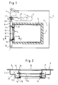
- Fig. 1
- eine schematische Schnittdarstellung des Back-ofens,
- Fig. 2
- eine vergrößerte Schnittdarstellung der Ofentür gemäß der Schnittlinie II-II in Fig. 1.
- Fig. 1
- is a schematic sectional view of the oven,
- Fig. 2
- an enlarged sectional view of the furnace door along the section line II-II in Fig. 1st
Beim Ausführungsbeispiel gemäß Fig. 1 ist innerhalb eines
Ofengehäuses 1 eine von einer thermischen Isolation 2 umgebene
Ofenmuffel 3 angeordnet, deren Heizelemente nicht dargestellt
sind. Oberhalb der Ofenmuffel und unterhalb einer
elektrischen Steuereinrichtung 4 befindet sich ein Kühlluftgebläse
5 zur Abführung der in dem Gehäuseraum zwischen
Ofenmuffel 3 und Ofengehäuse 1 befindlichen erwärmten Luft,
dessen Druckseite an einen Abluftkanal 6 angeschlossen ist,
der wiederum in einen z.B. über einen Großteil der Backofenbreite
sich erstreckenden Lüftungsschlitz 7 an der Backofenfrontseite
unterhalb der Steuereinrichtung einmündet, durch
welchen hindurch die erwärmte Abluft nach außen abgeführt
wird (siehe Pfeilrichtung). Die einseitig offene Ofenmuffel
3 ist verschließbar durch eine Ofentür 8, die im wesentlichen
gebildet ist aus einer frontseitigen, großflächigen
Glasscheibe 9, die im Mittelbereich einen z.B. rechteckigen,
transparenten und ein Durchsichtfenster 10 bildenden Scheibenbereich
aufweist, während die Glasscheibe 9 außerhalb
dieses Durchsichtfensters nicht transparent, z.B. mit einer
Bedruckung versehen ist. Träger dieser Glasscheibe 9 ist ein
metallischer Türboden 11, gebildet durch zwei stufenförmige
Abschnitte 11.1 und 11.2 (siehe hierzu Fig. 2). Mit freiem
Luftabstand zur frontseitigen Glasscheibe 9 angeordnet ist
eine allgemein mit 12 bezeichnete Fensterbaugruppe 12 mit in
einem Verbundrahmen 13 angeordneten Glasscheiben 14, die einen
Glasscheibenverbund bilden. Zwischen einem, dem Inneren
der Ofenmuffel 3 zugewandten, die Durchsichtöffnung umziehenden
Flansch 15 des Türbodens 11 und dem Scheibenverbund
13/14 befindet sich eine Dichtung 16, z.B. eine Glasseiden-Dichtung,
die bei pyrolytisch Selbstreinigendem Betrieb des
Backofens anstelle einer Gummidichtung erforderlich ist.
Z.B. durch diese Dichtung 16 hindurch oder durch andere
Leckstellen am Türboden 11 hindurch gelangt bei Betrieb des
Backofens Wrasen oder Dampf in das Innere der Türbaugruppe,
wobei davon ausgegangen werden darf, daß der Glasscheibenverbund
13/14 dampfdicht ausgebildet ist. Dieser Dampf gelangt
unterhalb und oberhalb des Durchsichtfensters 10 in
die Hohlräume 17 des Türbodens 11 (siehe Pfeile in Fig. 2).
Um nun eine unmittelbare Strömung des Dampfes in den Bereich
des Durchsichtfensters 10 an der frontseitigen Glasscheibe 9
zu verhindern und um diesen Durchsichtbereich 10 von der im
Inneren der Tür von unten nach oben entsprechend den Pfeilen
in Fig. 1 stattfindenden Konvektionsströmung auszusparen ist
an der äußeren Begrenzung des Verbundrahmens 13 eine rahmenartige,
z.B. metallische Strömungsbarriere 18 befestigt, die
sich zumindest annähernd bis zur Innenfläche der frontseitigen
Glasscheibe 9 erstreckt, vorzugsweise sich an dieser Innenfläche
im Peripheriebereich des Durchsichtfensters 10 abstützt.
Diese Strömungsbarriere 18 ist gebildet durch rahmenartig
zusammengesetzte, beim Ausführungsbeispiel trichterartig
nach außen geneigte Luftleitbleche. Hierdurch wird
die durch eine untere Einlaßöffnung 19 (Fig. 1) in den Hohlraum
des Türbodens 11 in Pfeilrichtung einströmende und
durch natürliche Konvektion bei Erwärmung der Türbaugruppe
nach oben strömende Luft zumindest weitgehend vom Durchsichtfenster
10 ferngehalten, d.h. sie umströmt die Wärmebarriere
18 und wird durch eine obere Luftauslaßöffnung 20
ins Freie abgeleitet, begünstigt durch die Injektorwirkung
des vom Kühlluftgebläse 5 ausgehenden erzwungenen Luftstromes.1 is within a
Furnace housing 1 one surrounded by
Claims (4)
- Baking oven with an oven muffle closable by an oven door, wherein the oven door has in the middle region a transparent window with a glass plate at the front side and therebehind and within a door base facing the muffle interior a window subassembly with at least one further glass pane and air openings for guidance past of a convection air current into the cavity enclosed by the door base, characterised thereby that a flow barrier (18) is provided between the window subassembly (12) and the circumference of the transparent window (10) of the glass pane (9) at the front side.
- Baking oven according to claim 1, characterised thereby that the flow barrier (18) is constructed in the form of air guide plates which are joined together in frame-like manner and which are arranged at the window subassembly (12) and extend out from this at least almost up to the glass pane (9) at the front side.
- Baking oven according to one of the preceding claims, characterised thereby that air outlet openings (20) which are preferably elongate are provided at the upper side of the cavity enclosed by the door base (11).
- Baking oven according to claim 3, characterised thereby that the air outlet openings (20) are disposed in immediate proximity of ventilation slots (7), which are arranged at the door upper side, for the outflows, which are constrainedly produced by a cooling air fan (5) provided in the baking oven housing (1), of exhaust air.
Priority Applications (3)
| Application Number | Priority Date | Filing Date | Title |
|---|---|---|---|
| EP19950103199 EP0731318B1 (en) | 1995-03-06 | 1995-03-06 | Baking oven |
| ES95103199T ES2125504T3 (en) | 1995-03-06 | 1995-03-06 | OVEN. |
| DE59503694T DE59503694D1 (en) | 1995-03-06 | 1995-03-06 | oven |
Applications Claiming Priority (1)
| Application Number | Priority Date | Filing Date | Title |
|---|---|---|---|
| EP19950103199 EP0731318B1 (en) | 1995-03-06 | 1995-03-06 | Baking oven |
Publications (2)
| Publication Number | Publication Date |
|---|---|
| EP0731318A1 EP0731318A1 (en) | 1996-09-11 |
| EP0731318B1 true EP0731318B1 (en) | 1998-09-23 |
Family
ID=8219043
Family Applications (1)
| Application Number | Title | Priority Date | Filing Date |
|---|---|---|---|
| EP19950103199 Expired - Lifetime EP0731318B1 (en) | 1995-03-06 | 1995-03-06 | Baking oven |
Country Status (3)
| Country | Link |
|---|---|
| EP (1) | EP0731318B1 (en) |
| DE (1) | DE59503694D1 (en) |
| ES (1) | ES2125504T3 (en) |
Cited By (3)
| Publication number | Priority date | Publication date | Assignee | Title |
|---|---|---|---|---|
| WO2001069137A1 (en) | 2000-03-15 | 2001-09-20 | Schott Glas | Window for a hot chamber that is sealed off from the surroundings |
| KR20160015916A (en) * | 2014-08-01 | 2016-02-15 | 삼성전자주식회사 | Oven and door assembly applying the same |
| WO2023249234A1 (en) * | 2022-06-21 | 2023-12-28 | 엘지전자 주식회사 | Cooking apparatus |
Families Citing this family (7)
| Publication number | Priority date | Publication date | Assignee | Title |
|---|---|---|---|---|
| DE19705120A1 (en) * | 1997-02-11 | 1998-08-13 | Gaggenau Hausgeraete Gmbh | Oven door |
| DE19738602A1 (en) * | 1997-09-04 | 1999-03-11 | Aeg Hausgeraete Gmbh | Process for removing cooking condensate from an oven muffle and cooking oven with means for removing cooking condensate |
| DE10231338A1 (en) * | 2002-07-11 | 2004-02-12 | Electrolux Home Products Corporation N.V. | Cooking oven |
| DE10337438A1 (en) * | 2003-08-14 | 2005-03-10 | Bsh Bosch Siemens Hausgeraete | Oven door and door floor for it |
| DE102009033404A1 (en) * | 2009-07-15 | 2011-01-27 | Miele & Cie. Kg | household appliance |
| ES2393150B1 (en) * | 2010-03-26 | 2013-10-23 | Bsh Electrodomésticos España, S.A. | DOOR UNIT OF COOKING APPLIANCE. |
| CN107692861A (en) * | 2017-09-28 | 2018-02-16 | 广东美的厨房电器制造有限公司 | Cooker |
Family Cites Families (1)
| Publication number | Priority date | Publication date | Assignee | Title |
|---|---|---|---|---|
| US3760792A (en) * | 1972-09-05 | 1973-09-25 | Gen Electric | Flow-through shutter for oven door window |
-
1995
- 1995-03-06 ES ES95103199T patent/ES2125504T3/en not_active Expired - Lifetime
- 1995-03-06 EP EP19950103199 patent/EP0731318B1/en not_active Expired - Lifetime
- 1995-03-06 DE DE59503694T patent/DE59503694D1/en not_active Expired - Fee Related
Cited By (5)
| Publication number | Priority date | Publication date | Assignee | Title |
|---|---|---|---|---|
| WO2001069137A1 (en) | 2000-03-15 | 2001-09-20 | Schott Glas | Window for a hot chamber that is sealed off from the surroundings |
| US6601575B2 (en) | 2000-03-15 | 2003-08-05 | Schott Glas | Window for a hot chamber that is sealed off from the surroundings |
| KR20160015916A (en) * | 2014-08-01 | 2016-02-15 | 삼성전자주식회사 | Oven and door assembly applying the same |
| KR102219929B1 (en) | 2014-08-01 | 2021-02-25 | 삼성전자주식회사 | Oven and door assembly applying the same |
| WO2023249234A1 (en) * | 2022-06-21 | 2023-12-28 | 엘지전자 주식회사 | Cooking apparatus |
Also Published As
| Publication number | Publication date |
|---|---|
| DE59503694D1 (en) | 1998-10-29 |
| EP0731318A1 (en) | 1996-09-11 |
| ES2125504T3 (en) | 1999-03-01 |
Similar Documents
| Publication | Publication Date | Title |
|---|---|---|
| EP0752561B1 (en) | Cooking oven | |
| EP0476364B1 (en) | Baking oven | |
| EP0731318B1 (en) | Baking oven | |
| DE2830342A1 (en) | BUILT-IN DOUBLE OVEN | |
| DE102009033404A1 (en) | household appliance | |
| DE4407084A1 (en) | Baking oven with window assembly and ventilation arrangement | |
| EP0947776B1 (en) | Oven with cooling system | |
| CH678913A5 (en) | Oven for forced cooling - with heat transferred to air which flows along channels in oven walls and door | |
| DE102006001282A1 (en) | cooking appliance | |
| DE19504673C2 (en) | Built-in oven cooling | |
| DE2615604B2 (en) | Oven, in particular with means for pyrolytic cleaning with a cooling air fan | |
| DE19817197C2 (en) | Arrangement with oven and hob | |
| EP0633433A1 (en) | Built in kitchen-range | |
| DE3027566C2 (en) | Oven with a vapor outlet duct | |
| DE10349313A1 (en) | Double glazed oven door with the cooling airflows from the side frames split into lower and upper paths to minimise the heating effect before entering the space between the windows | |
| DE2106772A1 (en) | Cooker, especially electric cooker | |
| DE10003997C2 (en) | Ventilated oven door | |
| DE3224369C2 (en) | ||
| DE10314214B4 (en) | Oven door for closing an oven muffle of an oven | |
| EP0654957A1 (en) | Built-in glass ceramic hob with several cooking surfaces heated by induction | |
| EP0940631A1 (en) | Pyrolytic self-cleaning cooking apparatus | |
| EP0029532A1 (en) | Combined stove for microwave and for conventional resistance heating | |
| DE19738602A1 (en) | Process for removing cooking condensate from an oven muffle and cooking oven with means for removing cooking condensate | |
| DE3625244A1 (en) | Baking and roasting oven door | |
| DE3742375A1 (en) | Oven with a cooking chamber which can be closed by an oven door, for cooking food |
Legal Events
| Date | Code | Title | Description |
|---|---|---|---|
| PUAI | Public reference made under article 153(3) epc to a published international application that has entered the european phase |
Free format text: ORIGINAL CODE: 0009012 |
|
| AK | Designated contracting states |
Kind code of ref document: A1 Designated state(s): DE ES FR GB IT NL |
|
| 17P | Request for examination filed |
Effective date: 19970305 |
|
| GRAG | Despatch of communication of intention to grant |
Free format text: ORIGINAL CODE: EPIDOS AGRA |
|
| GRAG | Despatch of communication of intention to grant |
Free format text: ORIGINAL CODE: EPIDOS AGRA |
|
| GRAH | Despatch of communication of intention to grant a patent |
Free format text: ORIGINAL CODE: EPIDOS IGRA |
|
| 17Q | First examination report despatched |
Effective date: 19980311 |
|
| GRAH | Despatch of communication of intention to grant a patent |
Free format text: ORIGINAL CODE: EPIDOS IGRA |
|
| RAP1 | Party data changed (applicant data changed or rights of an application transferred) |
Owner name: BSH BOSCH UND SIEMENS HAUSGERAETE GMBH |
|
| GRAA | (expected) grant |
Free format text: ORIGINAL CODE: 0009210 |
|
| AK | Designated contracting states |
Kind code of ref document: B1 Designated state(s): DE ES FR GB IT NL |
|
| GBT | Gb: translation of ep patent filed (gb section 77(6)(a)/1977) |
Effective date: 19980925 |
|
| REF | Corresponds to: |
Ref document number: 59503694 Country of ref document: DE Date of ref document: 19981029 |
|
| ET | Fr: translation filed | ||
| REG | Reference to a national code |
Ref country code: ES Ref legal event code: FG2A Ref document number: 2125504 Country of ref document: ES Kind code of ref document: T3 |
|
| PLBE | No opposition filed within time limit |
Free format text: ORIGINAL CODE: 0009261 |
|
| STAA | Information on the status of an ep patent application or granted ep patent |
Free format text: STATUS: NO OPPOSITION FILED WITHIN TIME LIMIT |
|
| 26N | No opposition filed | ||
| REG | Reference to a national code |
Ref country code: GB Ref legal event code: IF02 |
|
| PGFP | Annual fee paid to national office [announced via postgrant information from national office to epo] |
Ref country code: NL Payment date: 20020326 Year of fee payment: 8 |
|
| PGFP | Annual fee paid to national office [announced via postgrant information from national office to epo] |
Ref country code: GB Payment date: 20030227 Year of fee payment: 9 |
|
| PGFP | Annual fee paid to national office [announced via postgrant information from national office to epo] |
Ref country code: ES Payment date: 20030311 Year of fee payment: 9 |
|
| PGFP | Annual fee paid to national office [announced via postgrant information from national office to epo] |
Ref country code: FR Payment date: 20030319 Year of fee payment: 9 |
|
| PGFP | Annual fee paid to national office [announced via postgrant information from national office to epo] |
Ref country code: DE Payment date: 20030416 Year of fee payment: 9 |
|
| PG25 | Lapsed in a contracting state [announced via postgrant information from national office to epo] |
Ref country code: NL Free format text: LAPSE BECAUSE OF NON-PAYMENT OF DUE FEES Effective date: 20031001 |
|
| NLV4 | Nl: lapsed or anulled due to non-payment of the annual fee |
Effective date: 20031001 |
|
| PG25 | Lapsed in a contracting state [announced via postgrant information from national office to epo] |
Ref country code: GB Free format text: LAPSE BECAUSE OF NON-PAYMENT OF DUE FEES Effective date: 20040306 |
|
| PG25 | Lapsed in a contracting state [announced via postgrant information from national office to epo] |
Ref country code: ES Free format text: LAPSE BECAUSE OF NON-PAYMENT OF DUE FEES Effective date: 20040308 |
|
| PG25 | Lapsed in a contracting state [announced via postgrant information from national office to epo] |
Ref country code: DE Free format text: LAPSE BECAUSE OF NON-PAYMENT OF DUE FEES Effective date: 20041001 |
|
| GBPC | Gb: european patent ceased through non-payment of renewal fee | ||
| PG25 | Lapsed in a contracting state [announced via postgrant information from national office to epo] |
Ref country code: FR Free format text: LAPSE BECAUSE OF NON-PAYMENT OF DUE FEES Effective date: 20041130 |
|
| REG | Reference to a national code |
Ref country code: FR Ref legal event code: ST |
|
| PG25 | Lapsed in a contracting state [announced via postgrant information from national office to epo] |
Ref country code: IT Free format text: LAPSE BECAUSE OF NON-PAYMENT OF DUE FEES;WARNING: LAPSES OF ITALIAN PATENTS WITH EFFECTIVE DATE BEFORE 2007 MAY HAVE OCCURRED AT ANY TIME BEFORE 2007. THE CORRECT EFFECTIVE DATE MAY BE DIFFERENT FROM THE ONE RECORDED. Effective date: 20050306 |
|
| REG | Reference to a national code |
Ref country code: ES Ref legal event code: FD2A Effective date: 20040308 |