EP0730833B1 - Pneumatische Membranpresse - Google Patents
Pneumatische Membranpresse Download PDFInfo
- Publication number
- EP0730833B1 EP0730833B1 EP19960400465 EP96400465A EP0730833B1 EP 0730833 B1 EP0730833 B1 EP 0730833B1 EP 19960400465 EP19960400465 EP 19960400465 EP 96400465 A EP96400465 A EP 96400465A EP 0730833 B1 EP0730833 B1 EP 0730833B1
- Authority
- EP
- European Patent Office
- Prior art keywords
- lid
- plate
- fact
- membrane
- shaft
- Prior art date
- Legal status (The legal status is an assumption and is not a legal conclusion. Google has not performed a legal analysis and makes no representation as to the accuracy of the status listed.)
- Expired - Lifetime
Links
- 239000012528 membrane Substances 0.000 claims description 37
- 238000006073 displacement reaction Methods 0.000 claims description 6
- 230000000295 complement effect Effects 0.000 claims description 2
- 239000000853 adhesive Substances 0.000 claims 1
- 230000001070 adhesive effect Effects 0.000 claims 1
- 238000007689 inspection Methods 0.000 claims 1
- 238000012550 audit Methods 0.000 description 3
- 238000000465 moulding Methods 0.000 description 2
- 230000000717 retained effect Effects 0.000 description 2
- 208000031968 Cadaver Diseases 0.000 description 1
- 240000008042 Zea mays Species 0.000 description 1
- 238000006243 chemical reaction Methods 0.000 description 1
- 238000004891 communication Methods 0.000 description 1
- 239000002184 metal Substances 0.000 description 1
- 238000007747 plating Methods 0.000 description 1
- 230000001012 protector Effects 0.000 description 1
- 238000007789 sealing Methods 0.000 description 1
- 238000013022 venting Methods 0.000 description 1
Images


Classifications
-
- A—HUMAN NECESSITIES
- A43—FOOTWEAR
- A43D—MACHINES, TOOLS, EQUIPMENT OR METHODS FOR MANUFACTURING OR REPAIRING FOOTWEAR
- A43D25/00—Devices for gluing shoe parts
- A43D25/06—Devices for gluing soles on shoe bottoms
- A43D25/07—Devices for gluing soles on shoe bottoms using flexible diaphragm pressing devices
Definitions
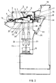
- the present invention relates to membrane bells pneumatic suitable for a press intended in particular for bonding or analog of bands on a body like, for example but not exclusively, soles on shoes or the like.
- the object of the present invention is to produce a bell with pneumatic membrane adapted to a press intended in particular for bonding or the like of bands on bodies such as shoes, which has a greater operational safety than bells known in the art prior.
- the pneumatic diaphragm bell adapted to a press intended in particular when bonding or the like to strips on a body 7 such as a shoe, comprises a support 20 of the body 7, a plate 19 surrounding this support, a hollow cover 1 whose edge has a shape suitable for come into contact with the plate, a flexible membrane 2, and means 4 for secure the edge of the membrane with the cover to define, with the bottom of it, a closed volume 50.
- the means 4 for secure the edge of the membrane 2 with the cover have a clamp 3 to trap the edge of the membrane with a complementary part of the cover and means 51 for controlling the movement of the clamp 3 relative to the cover 1.
- These means 51 to control the movement of the clamp relative to the cover are chosen from the following: screws, cylinder.
- the control means 51 are constituted by a plurality of cylinders distributed around the cover 1 and actuated for example by a single command button. These cylinders can be of any type, electric, pneumatic, etc.
- the bell further comprises a conduit 52 opening through one 53 of its ends, in the closed volume 50 and able to be connected, by its other end 54, to a source of compressed gas (not shown), and means for mounting the cover 1 in displacement relative to the plate 19 so that it can take at least two positions, a first position in which the edge of the cover rests on the plate 19 and a second position in which the edge of the cover is distant from the plate 19.
- the bell further comprises controllable sealing means of the conduit 52 to close the conduit when the cover is substantially in its second position and open it when the cover is substantially in its first position.
- the means for mounting the cover 1 moving relative to the plate 19 are constituted by rotation means 14 comprising a fixed shaft relative to the plate 19 and a bearing secured to the cover 1 and mounted in rotation on the shaft by a friction surface.
- the conduit 52 then comprises a first blind breakthrough made along the axis 12 of the shaft, an orifice connecting this first breakthrough with the wall lateral of this tree and being produced along an axis substantially perpendicular to the axis 12 of the shaft, a second breakthrough 15 made in the bearing and emerging through a first end 53 in the closed volume 50 and by its other second end 16 on the friction surface of the bearing which is pivotally mounted on the shaft, and a pipe portion 57 including one end is connected to the opening of the first breakthrough and the other of which end constitutes the end 54 of the conduit 52 defined above.
- Controllable means for opening the conduit when the cover 1 is substantially in its first position and close it when it is substantially in its second position are constituted by the fact that the second breakthrough 15 is made in the bearing so that when the cover 1 is in its first position, its second end 16 is opposite the orifice and that, when the cover is in its second position, the second end 16 of the second breakthrough 15 is not opposite the orifice, the friction surface closing the outlet of the orifice.
- the bell further comprises controllable means for putting in communication volume 50 with the ambient environment, with the aim of deflate or at least partially empty this volume preferably before the cover 1 does not pass from its first position to the second.
- the means controllable to port volume 50 with the environment ambient are advantageously constituted by a valve or the like controlled manually, pneumatically, etc., for example a two-way pneumatic distributor 55 mounted in series on the duct 52, advantageously on the pipe portion 57.
- a first passing lane is defined from end 54 to end 53, the second is defined from the end 53 towards the outlet 56 which is a venting.
- the bell structure described above is advantageous because it prevents the conduit 52 supplying the volume 50 with compressed gas is moved at the same time as cover 1, as would be the case if the conduit led directly into the volume without passing through the shaft and the bearing. Indeed, as this cover is very heavy, it is necessary, as it will be mentioned below, that he is balanced during his movements of his first position to second and vice versa, and it's almost impossible to achieve such balancing with a floating conduit, itself very heavy to because of its reinforced structure, which leads directly into volume 50.
- This structure also has the following advantage: if the cover 1 is actuated from its first position to the second while, by error, the distributor 55 was not correctly positioned (having remained by example in its passageway "54 to 53"), volume 50 will only receive one small additional amount of compressed gas. Likewise, it will prevent the volume 50 does not receive compressed gas too soon before cover 1 has been locked on the tray 19.
- the bell further comprises means for moving the support 20 of the body 7 in a direction substantially perpendicular to the plane of the plate 19 and a stop 9 integral with the cover 1 located in the closed volume 50, this stop being positioned on the path of movement of the support 20 when the cover is in its first position.
- the support 20 is provided with a removable plate 21 defining a light 22 intended to receive, by example as illustrated, a shoe 7, the removable plate being placed on a movable base 23 vertically adjustable by means for example of a bigorne 24 controlled by a motor 25.
- this support 20 can be constituted several auxiliary supports, for example two as illustrated on the figures.
- the two auxiliary supports are respectively controlled by two bigornes 24, 26 mounted in parallel and controlled respectively by two motors 25, 27 which, in the case where the body 7 is constituted by a shoe, respectively control the front of the shoe (the bighorn 24) and the heel (bighorn 26).
- the bell also includes means for lock the cover on the tray.
- These means can take different forms.
- One of their possible embodiments was schematically illustrated in Figures 1 and 3. They are in this case constituted by at least one hook 28 which hooks onto the plate 19 when the cover 1 is in its closed position.
- the bell further comprises one or more vision windows 6 made in the cover 1, which allow to see in inside the volume 50 after closing the cover 1 and checking, in particular, the positioning of the membrane 2 on the body 7.
- the cover must be able to pass from one of its positions to each other easily.
- the bell has means to control the rotation of the cover 1 relative to the plate.
- These means can be constituted, as illustrated in the figures, by a jack 13 of any type of which one end is connected to the cover 1. In the embodiment illustrated, its other end is connected to the frame 11 of the bell by a member turning 35.
- the bell also includes means for balance the cover in its rotation around the shaft.
- These means can be of any type, for example a spring, a counterweight, etc., and it is recalled that, as the structure described above avoids the presence of a conduit floating connected to the cover, balancing the cover is easier to achieve and remains constant whatever the position of the cover relative to the tray.
- the bell also includes, for example, screens protectors 17, 18 surrounding the shaft and the rotating bearing, these screens being advantageously secured to the frame 11 of the bell.
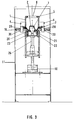
- Figure 2 shows the pneumatic diaphragm bell when the cover 1 is folded back in the closed position.
- Compressed air is supplied by the conduit 52 to volume 50, membrane 2 swells and hugs the entire surface of sole 29 of shoe 7, the pressure exerted by the membrane allowing the sole to adhere perfectly to the upper of the shoe 7.
- the pressure on the sole is reinforced by means of a fixed stop 9 advantageously on a metal cross member 8 on the upper part 5 of the cover 1.
- This stopper acts as a reaction to a booster 10 located at the bottom of the frame 11. It is of an appropriate shape corresponding to that of the sole 29 to stick on the upper of the shoe.
- FIG. 3 shows a transverse view in which the cover 1 is in the closed position, the membrane 2 applied to the sole 29 of the shoe 7.
- the cover 1 is locked by means of the hooks 28 coming from fit through the lights 30 made in the plate 19.
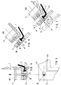
- FIG 4 is shown, in the clamped position, a cylinder clamping tire 51 adapted to cover 1, allowing tightening snapshot of the flange 3 energetically plating the edge of the membrane 2 on the edge of the cover 1 and the quick change of the membrane 2.
- FIG. 5 shows in detail a flat view of part of the clamping flange 3 of the membrane 2, provided with an oblong hole 31 facilitating, by simple movement of the clamp 3, the release of the means of fixing 32 of the jack 51 on the clamping flange 3, as well as a groove 34 of suitable shape cooperating with the lower part 36 of the bell for retain the edge of the membrane 2 in the form of a molding 33.
- FIG. 6 shows a detail of the pneumatic clamping cylinder 51 representing the fixing means 32 in the released position, the molding 33 of the membrane 2 which can then be released from the groove 34 of the clamping flange 3.
- Figure 7 are shown the different positions of the clamp 3 when changing the membrane 2.
- the pneumatic cylinder clamp 51 is in the released position and the clamp 3 has been moved, releasing the fixing means 32 through the oblong hole 31.
- Figure 8 shows a bottom view of the cover 1 making appear the membrane 2 retained by the clamp 3 with the holes oblong 31 allowing the release of the fixing means 32 of the flange tightening 3, during assembly or disassembly of the membrane 2, as well as the axis of articulation with a means 35 for fixing the bell on the frame 11 and the conduit 52 for the arrival of compressed air inside the closed volume 50 closed at 16 to ensure greater security, the air thus being unable to penetrate into the closed volume only when the cover 1 is locked on the plate 19 at by means of hooks 28.
Landscapes
- Footwear And Its Accessory, Manufacturing Method And Apparatuses (AREA)
- Tents Or Canopies (AREA)
- Actuator (AREA)
Claims (9)
- Druckluftmembranglocke für eine Presse, die insbesondere zum Kleben oder dergleichen von Bändern auf einen Körper (7) vorgesehen ist, mit:dadurch gekennzeichnet, daß die Leitung (52) wenigstens umfaßt:einem Träger (20) des Körpers,einer Platte (19), die den Träger umgibt,einem hohlen Deckel (1), dessen Rand eine Form aufweist, die so beschaffen ist, daß er mit der Platte in Kontakt gelangt,einer weichen Membran (2),Mitteln zum Befestigen des Randes der Membran am Deckel, um mit dessen Boden ein geschlossenes Volumen (50) zu definieren,einer Leitung (52), die mit einem Ende (53) in das geschlossene Volumen mündet und mit ihrem anderen Ende (54) mit einer Quelle für mit Druck beaufschlagtes Gas verbunden werden kann,Mitteln, mit denen der Deckel (1) in bezug auf die Platte (19) verschiebbar in der Weise angebracht werden kann, daß er wenigstens zwei Stellungen einnehmen kann, eine erste Stellung, in der der Rand des Deckels auf der Platte (19) aufliegt, und eine zweite Stellung, in der der Rand des Deckels von der Platte beabstandet ist, wobei diese Mittel für die in bezug auf die Platte verschiebbare Anbringung des Deckels durch Drehmittel (14) gebildet sind, wobei diese Drehmittel eine in bezug auf die Platte feste Welle und ein an der Welle über eine Reibfläche drehbar angebrachtes Lager, das mit dem Deckel fest verbunden ist, umfassen, undsteuerbaren Verschlußmitteln, die ermöglichen, die Leitung (52) zu verschließen, wenn sich der Deckel im wesentlichen in der zweiten Stellung befindet, und sie zu öffnen, wenn sich der Deckel in der ersten Stellung befindet,und daß die steuerbaren Verschlußmittel der Leitung (52) durch die Tatsache gebildet sind, daß die zweite Bohrung (15) in dem Lager in der Weise verwirklicht ist, daß, wenn sich der Deckel (1) in seiner ersten Stellung befindet, das zweite Ende (16) der zweiten Bohrung (15) sich gegenüber der Öffnung befindet, und daß, wenn sich der Deckel in seiner zweiten Stellung befindet, die Reibfläche den Ausgang der Öffnung verschließt.eine erste Blindbohrung, die längs der Achse (12) der Welle verwirklicht ist,eine Öffnung, die die erste Bohrung mit der Seitenwand der Welle verbindet und längs einer zur Achse der Welle im wesentlichen senkrechten Achse verwirklicht ist, undeine zweite Bohrung (15), die im Lager verwirklicht ist und mit einem ersten Ende (53) in das Volumen (50) mündet und mit seinem zweiten Ende (16) in die Reibfläche des an der Welle schwenkbar angebrachten Lagers mündet,
- Glocke nach Anspruch 1, dadurch gekennzeichnet, daß sie außerdem Mittel zum Verschieben des Trägers (20) des Körpers (7) in einer zu der Ebene der Platte (19) im wesentlichen senkrechten Richtung sowie einen mit dem Deckel fest verbundenen Anschlag (9) umfaßt, der sich in dem geschlossenen Volumen (50) befindet und auf der Verschiebungsbahn des Trägers (20) positioniert ist, wenn sich der Deckel (1) in seiner ersten Stellung befindet.
- Glocke nach einem der Ansprüche 1 und 2, dadurch gekennzeichnet, daß die Mittel zum Verbinden des Randes der Membran (2) mit dem Deckel einen Klemmflansch (3) zum Einschließen des Randes der Membran in einem komplementären Teil des Deckels, sowie Mittel (4) zum Steuern der Verschiebung des Klemmflansches in bezug auf den Deckel aufweisen.
- Glocke nach Anspruch 3, dadurch gekennzeichnet, daß die Mittel (4) zum Steuern der Verschiebung des Klemmflansches (3) in bezug auf den Deckel (1) aus den folgenden Elementen gewählt sind: Schraube, Stellzylinder.
- Glocke nach einem der vorhergehenden Ansprüche, dadurch gekennzeichnet, daß sie außerdem Mittel (28) zum Verriegeln des Deckels (1) an der Platte (19) umfaßt.
- Glocke nach einem der vorhergehenden Ansprüche, dadurch gekennzeichnet, daß der Träger (20) aus mehreren Hilfsträgern gebildet ist und daß sie Mittel (20, 24, 25, 26, 27) zum Verschieben der Hilfsträger in bezug auf die Platte (19) in einer zu der Ebene der Platte im wesentlichen senkrechten Richtung umfaßt.
- Glocke nach einem der vorhergehenden Ansprüche, dadurch gekennzeichnet, daß sie wenigstens ein Beobachtungsfenster (6) aufweist, das im Deckel (1) verwirklicht ist.
- Glocke nach einem der Ansprüche 1 bis 7, dadurch gekennzeichnet, daß sie Mittel (13) zum Steuern der Drehung des Deckels (1) in bezug auf die Platte (19) aufweist.
- Glocke nach einem der Ansprüche 1 bis 8, dadurch gekennzeichnet, daß sie Mittel aufweist, um den Deckel (1) bei seiner Drehung um die Welle im Gleichgewicht zu halten.
Applications Claiming Priority (2)
| Application Number | Priority Date | Filing Date | Title |
|---|---|---|---|
| FR9502801A FR2731327B1 (fr) | 1995-03-10 | 1995-03-10 | Cloche a membrane pneumatique adaptee sur une presse destinee notamment au collage des semelles sur les chaussures |
| FR9502801 | 1995-03-10 |
Publications (2)
| Publication Number | Publication Date |
|---|---|
| EP0730833A1 EP0730833A1 (de) | 1996-09-11 |
| EP0730833B1 true EP0730833B1 (de) | 2000-09-20 |
Family
ID=9476926
Family Applications (1)
| Application Number | Title | Priority Date | Filing Date |
|---|---|---|---|
| EP19960400465 Expired - Lifetime EP0730833B1 (de) | 1995-03-10 | 1996-03-05 | Pneumatische Membranpresse |
Country Status (4)
| Country | Link |
|---|---|
| EP (1) | EP0730833B1 (de) |
| DE (1) | DE69610344D1 (de) |
| ES (1) | ES2151134T3 (de) |
| FR (1) | FR2731327B1 (de) |
Families Citing this family (5)
| Publication number | Priority date | Publication date | Assignee | Title |
|---|---|---|---|---|
| FR2754683B1 (fr) * | 1996-10-18 | 1998-11-27 | Salomon Sa | Procede et dispositif de pressage pour assembler par collage une semelle avec une tige de chaussure |
| FR2839862B1 (fr) | 2002-05-24 | 2005-08-19 | Tech Et Realisations Mecanique | Machine pour coller une semelle sur l'empeigne d'une chaussure |
| CN102293484A (zh) * | 2011-08-31 | 2011-12-28 | 吴江源兴工艺鞋业有限公司 | 压鞋边机 |
| TWI757711B (zh) * | 2017-11-22 | 2022-03-11 | 荷蘭商耐克創新有限合夥公司 | 製鞋用之共形膜、壓力機及利用共形膜製造鞋製品的方法 |
| IT202200023781A1 (it) * | 2022-11-17 | 2024-05-17 | Irocol S R L | Pressa a membrana per l'incollaggio di calzature. |
Family Cites Families (3)
| Publication number | Priority date | Publication date | Assignee | Title |
|---|---|---|---|---|
| DE3338731C2 (de) * | 1983-10-25 | 1985-12-19 | Herbert Dr.-Ing. 8032 Gräfelfing Funck | Klebepresse zum Ankleben von Schuhsohlen an aufgeleistete Oberschuhe |
| GB2151904B (en) * | 1983-12-01 | 1987-04-01 | Quiles D Pascual Sansano | Machine for attaching soles to footwear |
| DE3516577A1 (de) * | 1985-05-08 | 1986-11-13 | Herbert Dr.-Ing. 8032 Gräfelfing Funck | Klebepresse zum ankleben von schuhsohlen an aufgeleistete oberschuhe |
-
1995
- 1995-03-10 FR FR9502801A patent/FR2731327B1/fr not_active Expired - Fee Related
-
1996
- 1996-03-05 ES ES96400465T patent/ES2151134T3/es not_active Expired - Lifetime
- 1996-03-05 EP EP19960400465 patent/EP0730833B1/de not_active Expired - Lifetime
- 1996-03-05 DE DE69610344T patent/DE69610344D1/de not_active Expired - Lifetime
Also Published As
| Publication number | Publication date |
|---|---|
| FR2731327B1 (fr) | 1997-05-23 |
| DE69610344D1 (de) | 2000-10-26 |
| EP0730833A1 (de) | 1996-09-11 |
| ES2151134T3 (es) | 2000-12-16 |
| FR2731327A1 (fr) | 1996-09-13 |
Similar Documents
| Publication | Publication Date | Title |
|---|---|---|
| FR2673972A1 (fr) | Porte d'acces, notamment pour nacelle de reacteur d'avion, munie d'un panneau articule a pivotement synchronise. | |
| FR2849429A1 (fr) | Bouchon de fermeture d'un flacon, a ouverture controlee | |
| CH407876A (fr) | Transport à lame d'air mobile | |
| EP3404176A1 (de) | Vorrichtung zum entriegeln eines türschlosses | |
| EP0730833B1 (de) | Pneumatische Membranpresse | |
| FR2720733A1 (fr) | Dispositif de remplissage comportant un collecteur de nettoyage fixé à un conduit de distribution. | |
| FR2460610A1 (fr) | Procede et installation d'irrigation, en particulier par aspersion, et appareil de commande utilisable dans une telle installation | |
| EP1165426A1 (de) | Behälter abfüllanlage mit integrierter reinigungseinrichtung | |
| EP0952376B1 (de) | Doppelsitzventil mit aufblasbarer Membran | |
| FR2943413A1 (fr) | Dispositif de transmission pour un capteur de position d'une boite de commande de turbocompresseur | |
| EP4255512A1 (de) | Diffusor zur befestigung an einem lüftungsgitter zur gesteuerten abgabe eines lufterfrischers | |
| FR3065438A1 (fr) | Systeme de prise d'air multiposition pour un aeronef | |
| EP0760306B1 (de) | Tankklappe | |
| FR2734770A1 (fr) | Installation d'eclairage equipant la partie avant d'un vehicule comportant une source lumineuse et un feu de signalisation | |
| FR2658060A1 (fr) | Porte-filtre pour une cafetiere ou une theiere muni d'un dispositif de securite contre un ecoulement non desire du liquide. | |
| EP1187683B1 (de) | Abgabevorrichtung für medien | |
| FR2528517A1 (fr) | Obturateur destine a etre monte dans un corps | |
| FR2781550A1 (fr) | Procede de changement d'une cartouche filtrante montee dans un conduit d'ecoulement d'un fluide et agencement pour la mise en oeuvre du procede | |
| FR2954794A1 (fr) | Dispositif d'obturation et ensemble correspondant | |
| EP0930412A1 (de) | Türscharnier mit Feststeller, insbesondere für ein Kraftfahrzeug | |
| EP1405796B1 (de) | Abgabevorrichtung für Flüssigkeiten | |
| EP0867570A1 (de) | Einbauspülkasten zur Top- oder Frontbetätigung | |
| EP1134341B1 (de) | Gelenktürsystem für Fahrzeuge, Behälter und dergleichen | |
| FR2846108A1 (fr) | Ensemble de verin et exutoire de fumee correspondant | |
| FR2739116A1 (fr) | Reservoir de chasse a encastrer a commande par le dessus ou en facade |
Legal Events
| Date | Code | Title | Description |
|---|---|---|---|
| PUAI | Public reference made under article 153(3) epc to a published international application that has entered the european phase |
Free format text: ORIGINAL CODE: 0009012 |
|
| AK | Designated contracting states |
Kind code of ref document: A1 Designated state(s): BE DE ES FR GB GR IT NL PT |
|
| 17P | Request for examination filed |
Effective date: 19970228 |
|
| 17Q | First examination report despatched |
Effective date: 19990305 |
|
| GRAG | Despatch of communication of intention to grant |
Free format text: ORIGINAL CODE: EPIDOS AGRA |
|
| GRAG | Despatch of communication of intention to grant |
Free format text: ORIGINAL CODE: EPIDOS AGRA |
|
| GRAH | Despatch of communication of intention to grant a patent |
Free format text: ORIGINAL CODE: EPIDOS IGRA |
|
| GRAH | Despatch of communication of intention to grant a patent |
Free format text: ORIGINAL CODE: EPIDOS IGRA |
|
| GRAA | (expected) grant |
Free format text: ORIGINAL CODE: 0009210 |
|
| AK | Designated contracting states |
Kind code of ref document: B1 Designated state(s): BE DE ES FR GB GR IT NL PT |
|
| PG25 | Lapsed in a contracting state [announced via postgrant information from national office to epo] |
Ref country code: NL Free format text: LAPSE BECAUSE OF FAILURE TO SUBMIT A TRANSLATION OF THE DESCRIPTION OR TO PAY THE FEE WITHIN THE PRESCRIBED TIME-LIMIT Effective date: 20000920 Ref country code: GR Free format text: LAPSE BECAUSE OF NON-PAYMENT OF DUE FEES Effective date: 20000920 Ref country code: GB Free format text: LAPSE BECAUSE OF FAILURE TO SUBMIT A TRANSLATION OF THE DESCRIPTION OR TO PAY THE FEE WITHIN THE PRESCRIBED TIME-LIMIT Effective date: 20000920 |
|
| REF | Corresponds to: |
Ref document number: 69610344 Country of ref document: DE Date of ref document: 20001026 |
|
| ITF | It: translation for a ep patent filed | ||
| REG | Reference to a national code |
Ref country code: ES Ref legal event code: FG2A Ref document number: 2151134 Country of ref document: ES Kind code of ref document: T3 |
|
| PG25 | Lapsed in a contracting state [announced via postgrant information from national office to epo] |
Ref country code: PT Free format text: LAPSE BECAUSE OF FAILURE TO SUBMIT A TRANSLATION OF THE DESCRIPTION OR TO PAY THE FEE WITHIN THE PRESCRIBED TIME-LIMIT Effective date: 20001220 |
|
| PG25 | Lapsed in a contracting state [announced via postgrant information from national office to epo] |
Ref country code: DE Free format text: LAPSE BECAUSE OF FAILURE TO SUBMIT A TRANSLATION OF THE DESCRIPTION OR TO PAY THE FEE WITHIN THE PRESCRIBED TIME-LIMIT Effective date: 20001221 |
|
| NLV1 | Nl: lapsed or annulled due to failure to fulfill the requirements of art. 29p and 29m of the patents act | ||
| GBV | Gb: ep patent (uk) treated as always having been void in accordance with gb section 77(7)/1977 [no translation filed] |
Effective date: 20000920 |
|
| PG25 | Lapsed in a contracting state [announced via postgrant information from national office to epo] |
Ref country code: BE Free format text: LAPSE BECAUSE OF NON-PAYMENT OF DUE FEES Effective date: 20010331 |
|
| PLBE | No opposition filed within time limit |
Free format text: ORIGINAL CODE: 0009261 |
|
| STAA | Information on the status of an ep patent application or granted ep patent |
Free format text: STATUS: NO OPPOSITION FILED WITHIN TIME LIMIT |
|
| 26N | No opposition filed | ||
| BERE | Be: lapsed |
Owner name: SOC. D'ETUDES TECHNIQUES ET REALISATIONS MECANIQUE Effective date: 20010331 |
|
| PGFP | Annual fee paid to national office [announced via postgrant information from national office to epo] |
Ref country code: ES Payment date: 20070315 Year of fee payment: 12 |
|
| PGFP | Annual fee paid to national office [announced via postgrant information from national office to epo] |
Ref country code: IT Payment date: 20070622 Year of fee payment: 12 |
|
| PGFP | Annual fee paid to national office [announced via postgrant information from national office to epo] |
Ref country code: FR Payment date: 20070326 Year of fee payment: 12 |
|
| REG | Reference to a national code |
Ref country code: FR Ref legal event code: ST Effective date: 20081125 |
|
| PG25 | Lapsed in a contracting state [announced via postgrant information from national office to epo] |
Ref country code: FR Free format text: LAPSE BECAUSE OF NON-PAYMENT OF DUE FEES Effective date: 20080331 |
|
| REG | Reference to a national code |
Ref country code: ES Ref legal event code: FD2A Effective date: 20080306 |
|
| PG25 | Lapsed in a contracting state [announced via postgrant information from national office to epo] |
Ref country code: ES Free format text: LAPSE BECAUSE OF NON-PAYMENT OF DUE FEES Effective date: 20080306 |
|
| PG25 | Lapsed in a contracting state [announced via postgrant information from national office to epo] |
Ref country code: IT Free format text: LAPSE BECAUSE OF NON-PAYMENT OF DUE FEES Effective date: 20080305 |