EP3301351A1 - Monoblock-halterung für leuchtvorrichtung mit mikrospiegel-matrix - Google Patents
Monoblock-halterung für leuchtvorrichtung mit mikrospiegel-matrix Download PDFInfo
- Publication number
- EP3301351A1 EP3301351A1 EP17192239.6A EP17192239A EP3301351A1 EP 3301351 A1 EP3301351 A1 EP 3301351A1 EP 17192239 A EP17192239 A EP 17192239A EP 3301351 A1 EP3301351 A1 EP 3301351A1
- Authority
- EP
- European Patent Office
- Prior art keywords
- support
- optical
- microsystem
- light
- shaping
- Prior art date
- Legal status (The legal status is an assumption and is not a legal conclusion. Google has not performed a legal analysis and makes no representation as to the accuracy of the status listed.)
- Granted
Links
Images
Classifications
-
- F—MECHANICAL ENGINEERING; LIGHTING; HEATING; WEAPONS; BLASTING
- F21—LIGHTING
- F21S—NON-PORTABLE LIGHTING DEVICES; SYSTEMS THEREOF; VEHICLE LIGHTING DEVICES SPECIALLY ADAPTED FOR VEHICLE EXTERIORS
- F21S41/00—Illuminating devices specially adapted for vehicle exteriors, e.g. headlamps
- F21S41/30—Illuminating devices specially adapted for vehicle exteriors, e.g. headlamps characterised by reflectors
- F21S41/39—Attachment thereof
-
- F—MECHANICAL ENGINEERING; LIGHTING; HEATING; WEAPONS; BLASTING
- F21—LIGHTING
- F21S—NON-PORTABLE LIGHTING DEVICES; SYSTEMS THEREOF; VEHICLE LIGHTING DEVICES SPECIALLY ADAPTED FOR VEHICLE EXTERIORS
- F21S41/00—Illuminating devices specially adapted for vehicle exteriors, e.g. headlamps
- F21S41/60—Illuminating devices specially adapted for vehicle exteriors, e.g. headlamps characterised by a variable light distribution
- F21S41/67—Illuminating devices specially adapted for vehicle exteriors, e.g. headlamps characterised by a variable light distribution by acting on reflectors
- F21S41/675—Illuminating devices specially adapted for vehicle exteriors, e.g. headlamps characterised by a variable light distribution by acting on reflectors by moving reflectors
-
- F—MECHANICAL ENGINEERING; LIGHTING; HEATING; WEAPONS; BLASTING
- F21—LIGHTING
- F21S—NON-PORTABLE LIGHTING DEVICES; SYSTEMS THEREOF; VEHICLE LIGHTING DEVICES SPECIALLY ADAPTED FOR VEHICLE EXTERIORS
- F21S43/00—Signalling devices specially adapted for vehicle exteriors, e.g. brake lamps, direction indicator lights or reversing lights
- F21S43/10—Signalling devices specially adapted for vehicle exteriors, e.g. brake lamps, direction indicator lights or reversing lights characterised by the light source
- F21S43/13—Signalling devices specially adapted for vehicle exteriors, e.g. brake lamps, direction indicator lights or reversing lights characterised by the light source characterised by the type of light source
- F21S43/14—Light emitting diodes [LED]
-
- F—MECHANICAL ENGINEERING; LIGHTING; HEATING; WEAPONS; BLASTING
- F21—LIGHTING
- F21S—NON-PORTABLE LIGHTING DEVICES; SYSTEMS THEREOF; VEHICLE LIGHTING DEVICES SPECIALLY ADAPTED FOR VEHICLE EXTERIORS
- F21S43/00—Signalling devices specially adapted for vehicle exteriors, e.g. brake lamps, direction indicator lights or reversing lights
- F21S43/10—Signalling devices specially adapted for vehicle exteriors, e.g. brake lamps, direction indicator lights or reversing lights characterised by the light source
- F21S43/19—Attachment of light sources or lamp holders
-
- F—MECHANICAL ENGINEERING; LIGHTING; HEATING; WEAPONS; BLASTING
- F21—LIGHTING
- F21S—NON-PORTABLE LIGHTING DEVICES; SYSTEMS THEREOF; VEHICLE LIGHTING DEVICES SPECIALLY ADAPTED FOR VEHICLE EXTERIORS
- F21S43/00—Signalling devices specially adapted for vehicle exteriors, e.g. brake lamps, direction indicator lights or reversing lights
- F21S43/20—Signalling devices specially adapted for vehicle exteriors, e.g. brake lamps, direction indicator lights or reversing lights characterised by refractors, transparent cover plates, light guides or filters
- F21S43/26—Refractors, transparent cover plates, light guides or filters not provided in groups F21S43/235 - F21S43/255
-
- F—MECHANICAL ENGINEERING; LIGHTING; HEATING; WEAPONS; BLASTING
- F21—LIGHTING
- F21S—NON-PORTABLE LIGHTING DEVICES; SYSTEMS THEREOF; VEHICLE LIGHTING DEVICES SPECIALLY ADAPTED FOR VEHICLE EXTERIORS
- F21S43/00—Signalling devices specially adapted for vehicle exteriors, e.g. brake lamps, direction indicator lights or reversing lights
- F21S43/30—Signalling devices specially adapted for vehicle exteriors, e.g. brake lamps, direction indicator lights or reversing lights characterised by reflectors
- F21S43/31—Optical layout thereof
-
- F—MECHANICAL ENGINEERING; LIGHTING; HEATING; WEAPONS; BLASTING
- F21—LIGHTING
- F21S—NON-PORTABLE LIGHTING DEVICES; SYSTEMS THEREOF; VEHICLE LIGHTING DEVICES SPECIALLY ADAPTED FOR VEHICLE EXTERIORS
- F21S43/00—Signalling devices specially adapted for vehicle exteriors, e.g. brake lamps, direction indicator lights or reversing lights
- F21S43/30—Signalling devices specially adapted for vehicle exteriors, e.g. brake lamps, direction indicator lights or reversing lights characterised by reflectors
- F21S43/37—Attachment thereof
-
- F—MECHANICAL ENGINEERING; LIGHTING; HEATING; WEAPONS; BLASTING
- F21—LIGHTING
- F21S—NON-PORTABLE LIGHTING DEVICES; SYSTEMS THEREOF; VEHICLE LIGHTING DEVICES SPECIALLY ADAPTED FOR VEHICLE EXTERIORS
- F21S45/00—Arrangements within vehicle lighting devices specially adapted for vehicle exteriors, for purposes other than emission or distribution of light
- F21S45/40—Cooling of lighting devices
- F21S45/47—Passive cooling, e.g. using fins, thermal conductive elements or openings
-
- F—MECHANICAL ENGINEERING; LIGHTING; HEATING; WEAPONS; BLASTING
- F21—LIGHTING
- F21V—FUNCTIONAL FEATURES OR DETAILS OF LIGHTING DEVICES OR SYSTEMS THEREOF; STRUCTURAL COMBINATIONS OF LIGHTING DEVICES WITH OTHER ARTICLES, NOT OTHERWISE PROVIDED FOR
- F21V29/00—Protecting lighting devices from thermal damage; Cooling or heating arrangements specially adapted for lighting devices or systems
- F21V29/50—Cooling arrangements
- F21V29/70—Cooling arrangements characterised by passive heat-dissipating elements, e.g. heat-sinks
- F21V29/74—Cooling arrangements characterised by passive heat-dissipating elements, e.g. heat-sinks with fins or blades
-
- F—MECHANICAL ENGINEERING; LIGHTING; HEATING; WEAPONS; BLASTING
- F21—LIGHTING
- F21V—FUNCTIONAL FEATURES OR DETAILS OF LIGHTING DEVICES OR SYSTEMS THEREOF; STRUCTURAL COMBINATIONS OF LIGHTING DEVICES WITH OTHER ARTICLES, NOT OTHERWISE PROVIDED FOR
- F21V5/00—Refractors for light sources
- F21V5/002—Refractors for light sources using microoptical elements for redirecting or diffusing light
-
- F—MECHANICAL ENGINEERING; LIGHTING; HEATING; WEAPONS; BLASTING
- F21—LIGHTING
- F21Y—INDEXING SCHEME ASSOCIATED WITH SUBCLASSES F21K, F21L, F21S and F21V, RELATING TO THE FORM OR THE KIND OF THE LIGHT SOURCES OR OF THE COLOUR OF THE LIGHT EMITTED
- F21Y2115/00—Light-generating elements of semiconductor light sources
- F21Y2115/10—Light-emitting diodes [LED]
Definitions
- the invention relates to the field of lighting and light signaling, in particular for a motor vehicle. More particularly, the invention relates to a signaling light device capable of producing luminous pictograms by means of an electromechanical microsystem with a matrix of micro-mirrors.
- the published patent document US 2015/0175054 A1 discloses a light device for a motor vehicle headlamp.
- the device comprises a light source of the laser type, an electromechanical microsystem serving as a deflector of the laser light, a phosphor phosphor element able to convert the monochromatic light reflected by the deflector, and an optical device comprising several lenses receiving the white light from the phosphor element.
- the deflector can be controlled so as to modulate the light image thus produced.
- the device comprises a support for supporting these different elements.
- the support consists of several parts assembled to each other, directly or indirectly as for example via the housing of the device or the projector. Such an assembly, however, results in forming tolerance chains decreasing the relative positioning accuracy of the various elements.
- the deflector is disposed on the inner face of a wall of the support, whereas this type component is usually fixed on a printed circuit board, such a platen being potentially bulky, especially when many electronic components are needed for the control of the deflector.
- the invention aims to overcome at least one of the disadvantages of the state of the art mentioned above. More particularly, the object of the invention is to propose a solution ensuring precise positioning of the optical components of a light device comprising an electromechanical microsystem provided with one or more mirrors.
- the subject of the invention is a luminous module support, in particular for a motor vehicle, comprising: an area for receiving at least one light source; a reception zone of an optical device for shaping the light emitted by the light source (s); a reception zone of an electromechanical microsystem with at least one mirror capable of receiving the rays coming from the optical shaping device; and a reception zone of at least one projection optical device receiving the rays reflected by the mirror (s) of the electromechanical microsystem; remarkable in that the support forms a cavity with an opening and comprises an outer surface around said opening, said surface forming the receiving zone of the microsystem.
- the support comprises an integral body, preferably made of aluminum, said body forming the reception zones of the light source or sources, the optical shaping device and the optical device of FIG. projection.
- the support comprises a plate adapted to be fixed to the body in order to partially close the cavity and comprising the outer surface forming the receiving zone of the microsystem.
- the cavity is covered with an antireflection coating, and / or absorbent, preferably black.
- the cavity is delimited by the receiving zone of the optical shaping device and the receiving zone of the projection optical device.
- At least one, preferably each, of the reception zones of the optical devices comprises an orifice made in the support and a shoulder around said orifice.
- the device comprises, within the cavity, a cantilevered tongue with an orifice intended to be traversed by the light reflected by the microsystem towards the projection optical device.
- the invention also relates to a light device, in particular for a motor vehicle, comprising: a support; at least one light source disposed on the support; an optical device for shaping the light emitted by the light source or sources, said device being disposed on the support; a microsystem electromechanical with at least one mirror adapted to receive the rays from the optical shaping device, said microsystem being disposed on the support; and an optical projection device adapted to receive the light reflected by the mirror (s) of the electromechanical microsystem, said device being disposed on the support; remarkable in that the support is in accordance with the invention.
- the light source or sources, the optical shaping device and the microsystem form a first optical axis
- the said microsystem and the optical projection device form a second optical axis, the angle between said optical axes being between 40 ° and 65 °, preferably between 45 ° and 60 °.
- the light source (s) are of the electroluminescence diode type on a plate arranged on a radiator fixed on the reception zone of said light source (s).
- the light source (s), of the electroluminescence diode type are arranged via a base directly on the radiator fixed on the reception zone of said light source (s). .
- the optical shaping device comprises a biconvex lens and / or the projection device comprises a biconvex lens and a biconcave lens.
- the or each lens of the optical device or devices is held in place by a flange, fixed for example by screwing, gluing, soldering, crimping, pegging, by means of ankle or rivets, or any other means of attachment, or by the combination of two or more of these means.
- the optical shaping device has a diameter greater than twice, preferably three times, that of the optical projection device.
- the microsystem is on a printed circuit board, said plate being fixed to the support so as to press said microsystem against the reception zone of said microsystem.
- the light device is a signal rear light capable of forming pictograms in the light beam produced, said pictograms being a function of a programming of the microsystem.
- the measurements of the invention are interesting in that they make it possible to ensure exact positioning of the various components, including the electromechanical microsystem while it is on a printed circuit board.
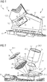
- the figure 1 is a perspective representation of a light device 2 according to the invention.
- the light device 2 is in this case a light signaling device for a motor vehicle. It comprises, essentially a support 4, optical components disposed on the support 4 and a printed circuit board 6 with electronic components and an electromechanical optical microsystem 8.
- the latter comprises a matrix of micro-mirrors adapted to be pivotally controlled by individual way.
- Such a microsystem is commonly called a micro-mirror array or DMD (acronym for "Digital Micromirror Device”).
- DMD digital Micromirror Device
- Each mirror can take two positions: it can tilt from 10 to 15 ° along the same axis so as to reflect the light either towards a diffusion lens or towards an absorbing surface. They say he switched "on” or “off” this regime is therefore binary.
- Such a microsystem is in itself well known to those skilled in the art.
- the support 4 of the light device 2 comprises a body 10 on which is mounted a radiator 12.
- the latter comprises an extended portion 12.1 receiving a plate 14 with one or more light sources 16, for example of the electroluminescence diode type.
- the radiator 12 also includes fins 12.2 extending substantially parallel to each other from the extended portion 12.1.
- the body 10 comprises a receiving zone 10.1 of the radiator 12 supporting the light source 16.
- the body forms a recess 18 opposite the light source 16.
- the bottom of this recess 18 forms a reception zone 10.2 of a shaping lens 20.
- the latter forms an optical device for shaping the light emitted by the light source 16.
- the body 10 forms a cavity (not visible at the figure 1 ) with an opening on the underside 10.3 of said body.
- the electromechanical microsystem 8 is disposed vis-à-vis this opening to receive the light beam formed by the forming lens 20.
- the body 10 also comprises a receiving zone 10.4 of an optical projection device 22.
- the latter may comprise two lenses, only one of which is visible at the figure 1 .
- the body 10 is advantageously in one piece, for example aluminum. It is the same for the radiator 12.
- Each of these two elements can be achieved by machining or molding followed possibly by machining operations.
- the figure 2 illustrates the optical components of the luminous device 2 of the figure 1 . These can be observed include a diaphragm 24 formed by a tongue 24.1 provided with a 24.2 orifice. The latter is disposed between the electromechanical microsystem 8 and the optical projection device 22. The role of the diaphragm is to cut the light rays which propagate too far from the nominal position to ensure a good definition, that is to say to say a good dive, from the image created by the system.
- the projection optical device 22 comprises a first lens 22.1 of the convergent type and a second lens 22.2 of the divergent type. The second lens has a substantial thickness to the point of having a generally cylindrical shape.
- the lens 20 for shaping the beam of light emitted by the light source 16 is a converging lens biconvex, configured to form a beam converging towards the optical microsystem and illuminating the optical surface of said system. It can be seen that the light source 16, the shaping lens 20 and the microsystem 8 are aligned along a first optical axis 26.1 and that said microsystem 8, the diaphragm 24 and the optical projection device 22 are aligned along a second axis optical 26.2.
- the angle ⁇ formed by these two optical axes is advantageously between 40 ° and 70 °, preferably between 50 ° and 70 °, or between 40 ° and 65 °, or between 45 ° and 60 °.
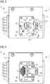
- the Figures 3 and 4 illustrate the luminous device of the figure 1 , without the plate and the electromechanical microsystem, seen from the underside of the support.
- the support 4 further comprises an element 28 for partially closing the cavity 30 within the body 10.
- This element 28 is formed by a plate 28.1 provided, at a peripheral portion, with means for attachment to the body 10, such as in particular holes for receiving fixing screws.
- the plate 28.1 is also provided, at a central portion, with an opening 28.2. This is intended to allow light from the shaping lens 20 to meet the optical part of the electromechanical microsystem disposed opposite the opening 28.2 in question.
- the element 28 may for this purpose include pads 28.3 forming bearing surfaces of the electromechanical microsystem. These pads 28.3, advantageously three in number to be isostatic, form surfaces comparable to point surfaces.
- the electromechanical microsystem attached to the printed circuit board can then be fixed to the support so that the electromechanical microsystem is in pressure on the pads 28.3, thus ensuring contact and hence exact positioning in the direction perpendicular to the face 10.3 of the body 10.
- Means for positioning the plate, in the plane of said plate may be provided, such as pins through holes in the plate and in the body 10 at the face 10.3.
- the tab 24.1 forming the diaphragm comprises at its end opposite the orifice 24.2 two orifices 24.3 cooperating with positioning rods embedded in the body. It also includes a 24.4 central mounting hole relative to the positioning holes 24.3, said orifice receiving a fixing screw engaging with the body 10.
- the body 10 comprises in the cavity 30 a recess forming a bearing surface of the tongue 24.1 , allowing it to pass under element 28 (according to the point of view of the figure 3 ).
- the orifice 24.2 is located at the end of the tongue 24.1 which is situated on the side of the shaping lens 20, so as to avoid any obstruction of the light beam propagating from the lens 20 of the formatting towards the electromechanical microsystem.
- the proximity between this beam and the edge of the tongue 24.1 at the orifice 24.2 is visible at the figure 2 .
- the figure 4 corresponds to the figure 3 , where however the element 28 is absent.
- the first lens 22.1 of the projection optical device 22 is held in place on the body 10 by means of a first flange 32.
- This can have an open profile, in this case U, with the opening directed to the forming lens 20.
- the shaping lens 20 and the first lens 22.1 are in fact very close to one another so that no space is available for a flange portion between the two lenses.
- the first flange 32 is advantageously fixed to the body 10 by screws engaging in threaded holes made in said body.
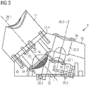
- the figure 5 is a sectional view of the light device of the figure 1 , the section being in a median longitudinal plane, that is to say in a plane generally parallel to the plane of the figure 1 and passing in the center of the device.
- the device in section at the figure 5 is shown without the printed circuit board and without the electromechanical microsystem.
- the shaping lens 20 comprises two attachment lugs 20.1 and 20.2 ( figure 2 ), these two ears being advantageously diametrically opposed. They are housed in cavities formed in the body 10, so as to ensure an angular orientation of the forming lens 20, the latter may not be symmetrical in revolution.
- a second flange 34 in this case circular and closed, is disposed on the peripheral edge of the forming lens 20, including the ears, and is fixed to the body by means of screws.
- the second lens 22.2 of the projection optical device is held in place by a third flange 36, also disposed on the peripheral edge of the second lens 22.2 and is fixed to the body by means of screws.
- the shaping lens 20 and the second lens 22.2 are placed from outside the body by insertion into the respective receiving areas.
- the first lens 22.1 is, in turn, put in place via the cavity 30.
Landscapes
- Engineering & Computer Science (AREA)
- General Engineering & Computer Science (AREA)
- Physics & Mathematics (AREA)
- Microelectronics & Electronic Packaging (AREA)
- Optics & Photonics (AREA)
- Non-Portable Lighting Devices Or Systems Thereof (AREA)
- Mechanical Engineering (AREA)
- Lighting Device Outwards From Vehicle And Optical Signal (AREA)
Applications Claiming Priority (1)
| Application Number | Priority Date | Filing Date | Title |
|---|---|---|---|
| FR1659227A FR3056685B1 (fr) | 2016-09-28 | 2016-09-28 | Support monobloc pour dispositif lumineux avec matrice de micro-miroirs |
Publications (2)
| Publication Number | Publication Date |
|---|---|
| EP3301351A1 true EP3301351A1 (de) | 2018-04-04 |
| EP3301351B1 EP3301351B1 (de) | 2025-10-01 |
Family
ID=57396688
Family Applications (1)
| Application Number | Title | Priority Date | Filing Date |
|---|---|---|---|
| EP17192239.6A Active EP3301351B1 (de) | 2016-09-28 | 2017-09-20 | Monoblock-halterung für leuchtvorrichtung mit mikrospiegel-matrix |
Country Status (4)
| Country | Link |
|---|---|
| US (1) | US10619818B2 (de) |
| EP (1) | EP3301351B1 (de) |
| CN (1) | CN107869695B (de) |
| FR (1) | FR3056685B1 (de) |
Cited By (1)
| Publication number | Priority date | Publication date | Assignee | Title |
|---|---|---|---|---|
| EP4328483A1 (de) * | 2022-08-25 | 2024-02-28 | ZKW Group GmbH | Verfahren zur automatisierten assemblierung eines lichtmoduls für einen kraftfahrzeugscheinwerfer |
Families Citing this family (1)
| Publication number | Priority date | Publication date | Assignee | Title |
|---|---|---|---|---|
| CN112839145A (zh) * | 2019-11-22 | 2021-05-25 | 余姚舜宇智能光学技术有限公司 | Tof摄像模组及其制造方法和电子设备 |
Citations (7)
| Publication number | Priority date | Publication date | Assignee | Title |
|---|---|---|---|---|
| US20050237620A1 (en) * | 2004-04-23 | 2005-10-27 | Nien-Hui Hsu | Heat dissipation structure for optical engine |
| US20060078266A1 (en) * | 2004-10-08 | 2006-04-13 | Wu Chao H | Optical engine and an image projector having the optical engine |
| US20080259290A1 (en) * | 2007-04-23 | 2008-10-23 | Coretronic Corporation | Projection apparatus |
| JP2014106270A (ja) * | 2012-11-26 | 2014-06-09 | Nippon Seiki Co Ltd | 表示装置 |
| US20150092435A1 (en) * | 2013-10-02 | 2015-04-02 | Koito Manufacturing Co., Ltd. | Vehicle headlamp |
| WO2016050503A1 (fr) * | 2014-10-02 | 2016-04-07 | Valeo Vision | Dispositif de signalisation à affichage de pictogrammes pour véhicule automobile, et feu de signalisation muni d'un tel dispositif lumineux. |
| JP2016091976A (ja) * | 2014-11-11 | 2016-05-23 | 株式会社小糸製作所 | 車両用灯具 |
Family Cites Families (21)
| Publication number | Priority date | Publication date | Assignee | Title |
|---|---|---|---|---|
| CN1086882A (zh) * | 1992-11-09 | 1994-05-18 | 林晓丹 | 用棱镜设计彩虹装饰灯具的方法 |
| US5796094A (en) * | 1993-02-26 | 1998-08-18 | Donnelly Corporation | Vehicle headlight control using imaging sensor |
| US7655894B2 (en) * | 1996-03-25 | 2010-02-02 | Donnelly Corporation | Vehicular image sensing system |
| US6355920B1 (en) * | 1998-10-09 | 2002-03-12 | Donnelly Corporation | Light-responsive vehicle control such as an electro-optic rearview mirror system that is adaptive to vehicle configuration |
| DE19946351B4 (de) * | 1999-09-28 | 2010-04-08 | Automotive Lighting Reutlingen Gmbh | Scheinwerfer für Fahrzeuge |
| US6890090B2 (en) * | 2001-08-08 | 2005-05-10 | Automotive Lighting Reutlingen Gmbh | Headlight for a motor vehicle |
| US6992573B2 (en) * | 2002-11-05 | 2006-01-31 | Donnelly Corporation | Vehicle rearview mirror system with protocol detection |
| KR20050090880A (ko) * | 2004-03-10 | 2005-09-14 | 엘지전자 주식회사 | 투사형 영상 표시 기기의 포커스 밸런스 조정 장치 및방법 |
| KR100713132B1 (ko) * | 2005-05-27 | 2007-05-02 | 삼성전자주식회사 | 프로젝터 |
| JP2010175583A (ja) * | 2009-01-27 | 2010-08-12 | Mitsubishi Electric Corp | 投写型表示装置 |
| WO2012124522A1 (ja) * | 2011-03-15 | 2012-09-20 | シャープ株式会社 | 発光装置、照明装置、前照灯および車両 |
| US8992056B2 (en) * | 2012-02-03 | 2015-03-31 | I/O Controls Corporation | Vehicle headlight and alert system |
| US9689549B2 (en) * | 2012-09-07 | 2017-06-27 | Mitsubishi Electric Corporation | Vehicle headlight device |
| AT513738B1 (de) * | 2012-12-20 | 2014-07-15 | Zizala Lichtsysteme Gmbh | Leuchteinheit für einen Scheinwerfer |
| US9658447B2 (en) * | 2013-12-09 | 2017-05-23 | Texas Instruments Incorporated | Multiple illumination sources for DMD lighting apparatus and methods |
| CN203949561U (zh) * | 2014-03-22 | 2014-11-19 | 珠海市春秋光学仪器有限公司 | 红点瞄准镜分划调节装置及开放式光学红点瞄准镜 |
| US10107467B2 (en) * | 2014-06-26 | 2018-10-23 | Texas Instruments Incorporated | Methods and apparatus for illumination with DMD and laser modulated adaptive beam shaping |
| TWM498387U (zh) * | 2014-06-30 | 2015-04-01 | 立碁電子工業股份有限公司 | 熱電分離的發光二極體封裝模組及電連接模組 |
| FR3038697B1 (fr) * | 2015-07-10 | 2017-08-11 | Valeo Vision | Procede de controle d’un faisceau lumineux et module d’eclairage et/ou de signalisation correspondant |
| CN205191235U (zh) * | 2015-10-27 | 2016-04-27 | 常志刚 | Led投影灯 |
| AT518266B1 (de) * | 2016-02-24 | 2017-09-15 | Zkw Group Gmbh | Halterungsvorrichtung für ein elektronisches Bauteil |
-
2016
- 2016-09-28 FR FR1659227A patent/FR3056685B1/fr active Active
-
2017
- 2017-09-20 EP EP17192239.6A patent/EP3301351B1/de active Active
- 2017-09-28 US US15/718,789 patent/US10619818B2/en active Active
- 2017-09-28 CN CN201710903205.4A patent/CN107869695B/zh active Active
Patent Citations (7)
| Publication number | Priority date | Publication date | Assignee | Title |
|---|---|---|---|---|
| US20050237620A1 (en) * | 2004-04-23 | 2005-10-27 | Nien-Hui Hsu | Heat dissipation structure for optical engine |
| US20060078266A1 (en) * | 2004-10-08 | 2006-04-13 | Wu Chao H | Optical engine and an image projector having the optical engine |
| US20080259290A1 (en) * | 2007-04-23 | 2008-10-23 | Coretronic Corporation | Projection apparatus |
| JP2014106270A (ja) * | 2012-11-26 | 2014-06-09 | Nippon Seiki Co Ltd | 表示装置 |
| US20150092435A1 (en) * | 2013-10-02 | 2015-04-02 | Koito Manufacturing Co., Ltd. | Vehicle headlamp |
| WO2016050503A1 (fr) * | 2014-10-02 | 2016-04-07 | Valeo Vision | Dispositif de signalisation à affichage de pictogrammes pour véhicule automobile, et feu de signalisation muni d'un tel dispositif lumineux. |
| JP2016091976A (ja) * | 2014-11-11 | 2016-05-23 | 株式会社小糸製作所 | 車両用灯具 |
Cited By (1)
| Publication number | Priority date | Publication date | Assignee | Title |
|---|---|---|---|---|
| EP4328483A1 (de) * | 2022-08-25 | 2024-02-28 | ZKW Group GmbH | Verfahren zur automatisierten assemblierung eines lichtmoduls für einen kraftfahrzeugscheinwerfer |
Also Published As
| Publication number | Publication date |
|---|---|
| CN107869695A (zh) | 2018-04-03 |
| CN107869695B (zh) | 2022-06-24 |
| FR3056685A1 (fr) | 2018-03-30 |
| EP3301351B1 (de) | 2025-10-01 |
| US10619818B2 (en) | 2020-04-14 |
| FR3056685B1 (fr) | 2021-01-15 |
| US20180087739A1 (en) | 2018-03-29 |
Similar Documents
| Publication | Publication Date | Title |
|---|---|---|
| EP4065882B1 (de) | Lichtmodul eines kraftfahrzeugs, das mit einem optischen element ausgestattet ist | |
| EP3999380B1 (de) | Beleuchtungsvorrichtung für ein kraftfahrzeug | |
| CA2810385A1 (fr) | Module optique de dispositif d'eclairage et/ou de signalisation d'un vehicule automobile | |
| EP3521692B1 (de) | Bifunktions-leuchtmodul mit gemeinsamer beleuchteter fläche | |
| CA2810700A1 (fr) | Module optique de dispositif d'eclairage et/ou de signalisation d'un vehicule automobile | |
| EP3201522A1 (de) | Leuchtvorrichtung eines fahrzeugs mit vorrichtung zum positionieren einer elektronischen platine | |
| EP3239598B1 (de) | Drehbares leuchtmodul | |
| EP3301351B1 (de) | Monoblock-halterung für leuchtvorrichtung mit mikrospiegel-matrix | |
| EP3190335A1 (de) | Leuchtvorrichtung, die mit einem gekrümmten umwandlungselement der wellenlänge ausgestattet ist, und scheinwerfer, der eine solche leuchtvorrichtung umfasst | |
| FR3056497A1 (fr) | Dispositif d'eclairage interieur variable pour vehicule | |
| EP2926049B1 (de) | Fahrzeugsignalisierungsvorrichtung mit dreidimensionaler wirkung | |
| FR3047210A1 (fr) | Dispositif lumineux avec plaque de renfort | |
| FR3047795A1 (fr) | Feu de signalisation avec faisceau focalisant en retrait de la surface exterieure dudit feu | |
| FR2853718A1 (fr) | Projecteur d'eclairage pour vehicule automobile comportant des moyens pour etaler transversalement le faisceau lumineux | |
| FR2726628A1 (fr) | Projecteur de vehicule automobile comportant deux reflecteurs separes, ainsi que des moyens de reglage d'orientation | |
| FR3056689B1 (fr) | Projecteur de vehicule automobile et systeme de projection comportant un tel projecteur | |
| EP3115681A1 (de) | Leuchtmodul für kfz-scheinwerfer | |
| EP4184054B1 (de) | Sicherheitsbeleuchtungsvorrichtung | |
| FR3062458A1 (fr) | Module de projection d'un faisceau lumineux pour dispositif d'emission lumineuse de vehicule automobile | |
| FR3011310A1 (fr) | Module d'eclairage et/ou de signalisation avec plusieurs systemes optiques rotatifs | |
| FR3077117A1 (fr) | Module lumineux pour vehicule automobile, et dispositif d'eclairage et/ou de signalisation muni d'un tel module | |
| FR3151258A1 (fr) | Dispositif optique pour un feu de signalisation lumineuse | |
| FR2749236A1 (fr) | Dispositif de maintien temporaire d'un bloc optique sur la carrosserie d'un vehicule automobile | |
| EP4499452A1 (de) | Leuchtmodul mit einer vorrichtung zur einstellung der ausrichtung eines lichtstrahls | |
| FR3146110A1 (fr) | Bloc optique de signalisation destiné à être intégré dans un projecteur de véhicule automobile |
Legal Events
| Date | Code | Title | Description |
|---|---|---|---|
| PUAI | Public reference made under article 153(3) epc to a published international application that has entered the european phase |
Free format text: ORIGINAL CODE: 0009012 |
|
| STAA | Information on the status of an ep patent application or granted ep patent |
Free format text: STATUS: THE APPLICATION HAS BEEN PUBLISHED |
|
| AK | Designated contracting states |
Kind code of ref document: A1 Designated state(s): AL AT BE BG CH CY CZ DE DK EE ES FI FR GB GR HR HU IE IS IT LI LT LU LV MC MK MT NL NO PL PT RO RS SE SI SK SM TR |
|
| AX | Request for extension of the european patent |
Extension state: BA ME |
|
| STAA | Information on the status of an ep patent application or granted ep patent |
Free format text: STATUS: REQUEST FOR EXAMINATION WAS MADE |
|
| 17P | Request for examination filed |
Effective date: 20180928 |
|
| RBV | Designated contracting states (corrected) |
Designated state(s): AL AT BE BG CH CY CZ DE DK EE ES FI FR GB GR HR HU IE IS IT LI LT LU LV MC MK MT NL NO PL PT RO RS SE SI SK SM TR |
|
| STAA | Information on the status of an ep patent application or granted ep patent |
Free format text: STATUS: EXAMINATION IS IN PROGRESS |
|
| 17Q | First examination report despatched |
Effective date: 20211015 |
|
| P01 | Opt-out of the competence of the unified patent court (upc) registered |
Effective date: 20230528 |
|
| GRAP | Despatch of communication of intention to grant a patent |
Free format text: ORIGINAL CODE: EPIDOSNIGR1 |
|
| STAA | Information on the status of an ep patent application or granted ep patent |
Free format text: STATUS: GRANT OF PATENT IS INTENDED |
|
| INTG | Intention to grant announced |
Effective date: 20250428 |
|
| GRAS | Grant fee paid |
Free format text: ORIGINAL CODE: EPIDOSNIGR3 |
|
| GRAA | (expected) grant |
Free format text: ORIGINAL CODE: 0009210 |
|
| STAA | Information on the status of an ep patent application or granted ep patent |
Free format text: STATUS: THE PATENT HAS BEEN GRANTED |
|
| AK | Designated contracting states |
Kind code of ref document: B1 Designated state(s): AL AT BE BG CH CY CZ DE DK EE ES FI FR GB GR HR HU IE IS IT LI LT LU LV MC MK MT NL NO PL PT RO RS SE SI SK SM TR |
|
| REG | Reference to a national code |
Ref country code: GB Ref legal event code: FG4D Free format text: NOT ENGLISH Ref country code: CH Ref legal event code: F10 Free format text: ST27 STATUS EVENT CODE: U-0-0-F10-F00 (AS PROVIDED BY THE NATIONAL OFFICE) Effective date: 20251001 |
|
| REG | Reference to a national code |
Ref country code: DE Ref legal event code: R096 Ref document number: 602017091989 Country of ref document: DE |
|
| REG | Reference to a national code |
Ref country code: IE Ref legal event code: FG4D Free format text: LANGUAGE OF EP DOCUMENT: FRENCH |
|
| REG | Reference to a national code |
Ref country code: NL Ref legal event code: MP Effective date: 20251001 |
|
| REG | Reference to a national code |
Ref country code: AT Ref legal event code: MK05 Ref document number: 1842802 Country of ref document: AT Kind code of ref document: T Effective date: 20251001 |
|
| PG25 | Lapsed in a contracting state [announced via postgrant information from national office to epo] |
Ref country code: NL Free format text: LAPSE BECAUSE OF FAILURE TO SUBMIT A TRANSLATION OF THE DESCRIPTION OR TO PAY THE FEE WITHIN THE PRESCRIBED TIME-LIMIT Effective date: 20251001 |
|
| PG25 | Lapsed in a contracting state [announced via postgrant information from national office to epo] |
Ref country code: ES Free format text: LAPSE BECAUSE OF FAILURE TO SUBMIT A TRANSLATION OF THE DESCRIPTION OR TO PAY THE FEE WITHIN THE PRESCRIBED TIME-LIMIT Effective date: 20251001 |
|
| REG | Reference to a national code |
Ref country code: LT Ref legal event code: MG9D |
|
| PG25 | Lapsed in a contracting state [announced via postgrant information from national office to epo] |
Ref country code: NO Free format text: LAPSE BECAUSE OF FAILURE TO SUBMIT A TRANSLATION OF THE DESCRIPTION OR TO PAY THE FEE WITHIN THE PRESCRIBED TIME-LIMIT Effective date: 20260101 |
|
| PG25 | Lapsed in a contracting state [announced via postgrant information from national office to epo] |
Ref country code: FI Free format text: LAPSE BECAUSE OF FAILURE TO SUBMIT A TRANSLATION OF THE DESCRIPTION OR TO PAY THE FEE WITHIN THE PRESCRIBED TIME-LIMIT Effective date: 20251001 Ref country code: HR Free format text: LAPSE BECAUSE OF FAILURE TO SUBMIT A TRANSLATION OF THE DESCRIPTION OR TO PAY THE FEE WITHIN THE PRESCRIBED TIME-LIMIT Effective date: 20251001 Ref country code: AT Free format text: LAPSE BECAUSE OF FAILURE TO SUBMIT A TRANSLATION OF THE DESCRIPTION OR TO PAY THE FEE WITHIN THE PRESCRIBED TIME-LIMIT Effective date: 20251001 |
|
| PG25 | Lapsed in a contracting state [announced via postgrant information from national office to epo] |
Ref country code: RS Free format text: LAPSE BECAUSE OF FAILURE TO SUBMIT A TRANSLATION OF THE DESCRIPTION OR TO PAY THE FEE WITHIN THE PRESCRIBED TIME-LIMIT Effective date: 20260101 |
|
| PG25 | Lapsed in a contracting state [announced via postgrant information from national office to epo] |
Ref country code: IS Free format text: LAPSE BECAUSE OF FAILURE TO SUBMIT A TRANSLATION OF THE DESCRIPTION OR TO PAY THE FEE WITHIN THE PRESCRIBED TIME-LIMIT Effective date: 20260201 |
|
| PG25 | Lapsed in a contracting state [announced via postgrant information from national office to epo] |
Ref country code: PT Free format text: LAPSE BECAUSE OF FAILURE TO SUBMIT A TRANSLATION OF THE DESCRIPTION OR TO PAY THE FEE WITHIN THE PRESCRIBED TIME-LIMIT Effective date: 20260202 Ref country code: CZ Free format text: LAPSE BECAUSE OF FAILURE TO SUBMIT A TRANSLATION OF THE DESCRIPTION OR TO PAY THE FEE WITHIN THE PRESCRIBED TIME-LIMIT Effective date: 20251001 |
|
| PG25 | Lapsed in a contracting state [announced via postgrant information from national office to epo] |
Ref country code: PL Free format text: LAPSE BECAUSE OF FAILURE TO SUBMIT A TRANSLATION OF THE DESCRIPTION OR TO PAY THE FEE WITHIN THE PRESCRIBED TIME-LIMIT Effective date: 20251001 |
|
| PG25 | Lapsed in a contracting state [announced via postgrant information from national office to epo] |
Ref country code: LV Free format text: LAPSE BECAUSE OF FAILURE TO SUBMIT A TRANSLATION OF THE DESCRIPTION OR TO PAY THE FEE WITHIN THE PRESCRIBED TIME-LIMIT Effective date: 20251001 |