EP0730833A1 - Pneumatische Membranpresse - Google Patents
Pneumatische Membranpresse Download PDFInfo
- Publication number
- EP0730833A1 EP0730833A1 EP96400465A EP96400465A EP0730833A1 EP 0730833 A1 EP0730833 A1 EP 0730833A1 EP 96400465 A EP96400465 A EP 96400465A EP 96400465 A EP96400465 A EP 96400465A EP 0730833 A1 EP0730833 A1 EP 0730833A1
- Authority
- EP
- European Patent Office
- Prior art keywords
- cover
- plate
- membrane
- bell
- bell according
- Prior art date
- Legal status (The legal status is an assumption and is not a legal conclusion. Google has not performed a legal analysis and makes no representation as to the accuracy of the status listed.)
- Granted
Links
- 239000012528 membrane Substances 0.000 claims abstract description 42
- 238000006073 displacement reaction Methods 0.000 claims description 5
- 238000004026 adhesive bonding Methods 0.000 claims description 3
- 230000000295 complement effect Effects 0.000 claims description 2
- 238000000465 moulding Methods 0.000 description 2
- 230000000717 retained effect Effects 0.000 description 2
- 208000031968 Cadaver Diseases 0.000 description 1
- 240000008042 Zea mays Species 0.000 description 1
- 238000012550 audit Methods 0.000 description 1
- 238000006243 chemical reaction Methods 0.000 description 1
- 239000002184 metal Substances 0.000 description 1
- 230000001681 protective effect Effects 0.000 description 1
- 238000007789 sealing Methods 0.000 description 1
Images

Classifications
-
- A—HUMAN NECESSITIES
- A43—FOOTWEAR
- A43D—MACHINES, TOOLS, EQUIPMENT OR METHODS FOR MANUFACTURING OR REPAIRING FOOTWEAR
- A43D25/00—Devices for gluing shoe parts
- A43D25/06—Devices for gluing soles on shoe bottoms
- A43D25/07—Devices for gluing soles on shoe bottoms using flexible diaphragm pressing devices
Definitions
- the present invention relates to pneumatic diaphragm bells adapted to a press intended in particular for bonding or the like to strips on a body such as, for example but not exclusively, the soles on shoes or the like.
- the object of the present invention is to produce a bell with a pneumatic membrane suitable for a press intended in particular for gluing or the like of strips on bodies such as shoes, which has greater operating safety than the bells known in the art. prior.
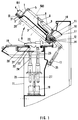
- the bell with pneumatic membrane adapted on a press intended in particular for gluing or the like of strips on a body 7 such as a shoe comprises a support 20 of the body 7, a plate 19 surrounding this support, a hollow cover 1 whose edge has a shape adapted to come into contact with the plate, a flexible membrane 2, and means 4 for securing the edge of the membrane with the cover to define, with the bottom thereof, a closed volume 50.
- the means 4 for securing the edge of the membrane 2 with the cover comprise a clamping flange 3 to trap the edge of the membrane with a complementary part of the cover and means 51 for controlling the movement of the clamping flange 3 relative to the cover 1.
- These means 51 for controlling the movement of the clamping flange relative to the cover are chosen from the following elements: screw, jack.
- the control means 51 are constituted by a plurality of jacks distributed around the cover 1 and actuated for example by a single control button. These cylinders can be of any type, electric, pneumatic, etc.
- the bell further comprises a conduit 52 opening, through one 53 of its ends, into the closed volume 50 and capable of being connected, by its other end 54, to a source of compressed gas (not shown), and means for mounting the cover 1 in displacement relative to the plate 19 so that it can take at least two positions, a first position in which the edge of the cover rests on the plate 19 and a second position in which the edge of the cover is distant of the plate 19.
- the bell further comprises controllable shutter means for the duct 52 making it possible to shut the duct when the cover is substantially in its second position and open it when the cover is substantially in its first position.
- the means for mounting the cover 1 in displacement relative to the plate 19 are constituted by rotation means 14 comprising a fixed shaft with respect to the plate 19 and a bearing integral with the cover 1 and mounted in rotation on the shaft by a friction surface.
- the conduit 52 then comprises a first blind breakthrough made along the axis 12 of the shaft, an orifice connecting this first breakthrough with the side wall of this shaft and being made along an axis substantially perpendicular to the axis 12 of the shaft , a second breakthrough 15 made in the bearing and opening by a first end 53 in the closed volume 50 and by its other second end 16 on the friction surface of the bearing which is pivotally mounted on the shaft, and a pipe portion 57, one end of which is connected to the opening of the first breakthrough and the other end of which constitutes the end 54 of the conduit 52 defined above.
- the controllable means for opening the duct when the cover 1 is substantially in its first position and closing it when it is substantially in its second position are constituted by the fact that the second breakthrough 15 is made in the bearing so that, when the cover 1 is in its first position, its second end 16 is opposite the orifice and that, when the cover is in its second position, the second end 16 of the second breakthrough 15 is not opposite the orifice, the friction surface sealing the outlet of the orifice.
- the bell further comprises controllable means for putting in communication the volume 50 with the ambient medium, with the aim of deflating or at least partially emptying this volume preferably before the cover 1 passes from its first position to the second.
- controllable means for bringing the volume 50 into communication with the ambient environment are advantageously constituted by a valve or the like controlled manually, pneumatically, etc., for example a two-way pneumatic distributor 55 mounted in series on the pipe 52, advantageously on the pipe portion 57.
- a first passway is defined from the end 54 towards the end 53, the second is defined from the end 53 towards the outlet 56 which is a setting to the atmosphere.
- the bell structure described above is advantageous because it makes it possible to prevent the conduit 52 for supplying the volume 50 with compressed gas from being moved at the same time as the cover 1, as would be the case if the conduit opened directly in the volume without passing through the shaft and the bearing.
- this cover is very heavy, it must, as will be mentioned below, that it be balanced during its movements from its first position to the second and vice versa, and it is almost impossible to achieve such balancing with a floating duct, itself very heavy because of its reinforced structure, which leads directly into volume 50.
- This structure also has the following advantage: if the cover 1 is actuated from its first position to the second when, by mistake, the dispenser 55 has not been properly positioned (for example, having remained in its passageway " 54 to 53 "), volume 50 will receive only a small additional quantity of compressed gas. Likewise, it will prevent the volume 50 from receiving compressed gas too soon before the cover 1 has been locked on the plate 19.
- the bell further comprises means for moving the support 20 of the body 7 in a direction substantially perpendicular to the plane of the plate 19 and a stop 9 secured to the cover 1 located in the closed volume 50, this stop being positioned on the path of movement of the support 20 when the cover is in its first position.
- the support 20 is provided with a removable plate 21 defining a lumen 22 intended to receive, for example as illustrated, a shoe 7, the removable plate being placed on a mobile base 23 adjustable vertically by means of example of a bighorn 24 controlled by a motor 25.
- this support 20 may consist of several auxiliary supports, for example two as illustrated in the figures.
- the two auxiliary supports are respectively controlled by two bigornes 24, 26 mounted in parallel and controlled respectively by two motors 25, 27 which, in the case where the body 7 is constituted by a shoe, respectively control the front of the shoe (the bigorne 24) and the heel (bigorne 26).
- the bell also includes means for locking the cover on the tray.
- These means can take different forms.
- One of their possible embodiments has been schematically illustrated in FIGS. 1 and 3. In this case, they consist of at least one hook 28 which hooks onto the plate 19 when the cover 1 is in its closed position. .
- the bell further comprises one or more viewing windows 6 made in the cover 1, which make it possible to see inside the volume 50 after closing the cover 1 and to control, in particular, the positioning of the membrane 2 on the body 7.
- the bell comprises means for controlling the rotation of the cover 1 relative to the plate.
- These means can be constituted, as illustrated in the figures, by a jack 13 of any type, one end of which is connected to the cover 1. In the illustrated embodiment, its other end is connected to the frame 11 of the bell by a rotating member. 35.
- the bell also includes means for balancing the cover in its rotation around the shaft.
- These means can be of any type, for example a spring, a counterweight, etc., and it is recalled that, as the structure described above avoids the presence of a floating duct connected to the cover, the balancing of the cover is easier to carry out and remains constant whatever the position of the cover relative to the tray.
- the bell also comprises, for example, protective screens 17, 18 surrounding the shaft and the rotating bearing, these screens being advantageously secured to the frame 11 of the bell.
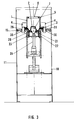
- FIG. 2 represents the pneumatic diaphragm bell when the cover 1 is folded down in the closed position.
- the compressed air is brought through the conduit 52 to the volume 50, the membrane 2 swells and hugs the entire surface of the sole 29 of the shoe 7, the pressure exerted by the membrane allowing the sole to adhere perfectly to the upper of the shoe 7.
- the pressure on the sole is reinforced by means of a stop 9 advantageously fixed on a metal cross member 8 on the upper part 5 of the cover 1.
- This stop serves as a reaction to a booster 10 located at the bottom of the frame 11. It is of an appropriate shape corresponding to that of the sole 29 to be glued on the upper of the shoe.
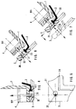
- FIG. 3 shows a transverse view in which the cover 1 is in the closed position, the membrane 2 applied to the sole 29 of the shoe 7.
- the cover 1 is locked by means of the hooks 28 which adapt through the slots 30 made in tray 19.
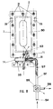
- FIG. 4 In FIG. 4 is shown, in the clamped position, a pneumatic clamping cylinder 51 adapted to the cover 1, allowing instantaneous tightening of the flange 3 energetically pressing the edge of the membrane 2 on the edge of the cover 1 and the rapid change of membrane 2.
- FIG. 5 shows in detail a flat view of part of the clamping flange 3 of the membrane 2, provided with an oblong hole 31 facilitating, by simple displacement of the clamping flange 3, the release of the fixing means 32 of the jack 51 on the clamping flange 3, as well as a groove 34 of suitable shape cooperating with the lower part 36 of the bell to retain the edge of the membrane 2 in the form of molding 33.
- FIG. 6 shows a detail of the pneumatic clamping cylinder 51 representing the fixing means 32 in the released position, the molding 33 of the membrane 2 can then be released from the groove 34 of the clamping flange 3.
- FIG. 7 are shown the different positions of the clamping flange 3 when changing the membrane 2.
- the pneumatic clamping cylinder 51 is in the released position and the clamping flange 3 has been moved, releasing the fixing means 32 through the oblong hole 31.
- Figure 8 shows a bottom view of the cover 1 showing the membrane 2 retained by the clamp 3 with the oblong holes 31 allowing the release of the fastening means 32 of the clamp 3, during assembly or disassembly of the membrane 2, as well as the axis of articulation with a means 35 for fixing the bell on the frame 11 and the conduit 52 for the arrival of compressed air inside the closed volume 50 closed at 16 to ensure a greater security, the air thus being able to enter the closed volume only when the cover 1 is locked on the plate 19 by means of the hooks 28.
Landscapes
- Footwear And Its Accessory, Manufacturing Method And Apparatuses (AREA)
- Tents Or Canopies (AREA)
- Actuator (AREA)
Applications Claiming Priority (2)
| Application Number | Priority Date | Filing Date | Title |
|---|---|---|---|
| FR9502801A FR2731327B1 (fr) | 1995-03-10 | 1995-03-10 | Cloche a membrane pneumatique adaptee sur une presse destinee notamment au collage des semelles sur les chaussures |
| FR9502801 | 1995-03-10 |
Publications (2)
| Publication Number | Publication Date |
|---|---|
| EP0730833A1 true EP0730833A1 (de) | 1996-09-11 |
| EP0730833B1 EP0730833B1 (de) | 2000-09-20 |
Family
ID=9476926
Family Applications (1)
| Application Number | Title | Priority Date | Filing Date |
|---|---|---|---|
| EP19960400465 Expired - Lifetime EP0730833B1 (de) | 1995-03-10 | 1996-03-05 | Pneumatische Membranpresse |
Country Status (4)
| Country | Link |
|---|---|
| EP (1) | EP0730833B1 (de) |
| DE (1) | DE69610344D1 (de) |
| ES (1) | ES2151134T3 (de) |
| FR (1) | FR2731327B1 (de) |
Cited By (4)
| Publication number | Priority date | Publication date | Assignee | Title |
|---|---|---|---|---|
| FR2839862A1 (fr) | 2002-05-24 | 2003-11-28 | Tech Et Realisations Mecanique | Machine pour coller une semelle sur l'empeigne d'une chaussure |
| CN102293484A (zh) * | 2011-08-31 | 2011-12-28 | 吴江源兴工艺鞋业有限公司 | 压鞋边机 |
| KR20220106847A (ko) * | 2017-11-22 | 2022-07-29 | 나이키 이노베이트 씨.브이. | 신발류 제조용 순응 멤브레인 |
| IT202200023781A1 (it) * | 2022-11-17 | 2024-05-17 | Irocol S R L | Pressa a membrana per l'incollaggio di calzature. |
Families Citing this family (1)
| Publication number | Priority date | Publication date | Assignee | Title |
|---|---|---|---|---|
| FR2754683B1 (fr) * | 1996-10-18 | 1998-11-27 | Salomon Sa | Procede et dispositif de pressage pour assembler par collage une semelle avec une tige de chaussure |
Citations (3)
| Publication number | Priority date | Publication date | Assignee | Title |
|---|---|---|---|---|
| EP0141183A2 (de) * | 1983-10-25 | 1985-05-15 | Herbert Dr.-Ing. Funck | Klebepresse für Schuhe |
| GB2151904A (en) * | 1983-12-01 | 1985-07-31 | Quiles D Pascual Sansano | Machine for attaching soles to footwear |
| DE3516577A1 (de) * | 1985-05-08 | 1986-11-13 | Herbert Dr.-Ing. 8032 Gräfelfing Funck | Klebepresse zum ankleben von schuhsohlen an aufgeleistete oberschuhe |
-
1995
- 1995-03-10 FR FR9502801A patent/FR2731327B1/fr not_active Expired - Fee Related
-
1996
- 1996-03-05 ES ES96400465T patent/ES2151134T3/es not_active Expired - Lifetime
- 1996-03-05 EP EP19960400465 patent/EP0730833B1/de not_active Expired - Lifetime
- 1996-03-05 DE DE69610344T patent/DE69610344D1/de not_active Expired - Lifetime
Patent Citations (3)
| Publication number | Priority date | Publication date | Assignee | Title |
|---|---|---|---|---|
| EP0141183A2 (de) * | 1983-10-25 | 1985-05-15 | Herbert Dr.-Ing. Funck | Klebepresse für Schuhe |
| GB2151904A (en) * | 1983-12-01 | 1985-07-31 | Quiles D Pascual Sansano | Machine for attaching soles to footwear |
| DE3516577A1 (de) * | 1985-05-08 | 1986-11-13 | Herbert Dr.-Ing. 8032 Gräfelfing Funck | Klebepresse zum ankleben von schuhsohlen an aufgeleistete oberschuhe |
Cited By (4)
| Publication number | Priority date | Publication date | Assignee | Title |
|---|---|---|---|---|
| FR2839862A1 (fr) | 2002-05-24 | 2003-11-28 | Tech Et Realisations Mecanique | Machine pour coller une semelle sur l'empeigne d'une chaussure |
| CN102293484A (zh) * | 2011-08-31 | 2011-12-28 | 吴江源兴工艺鞋业有限公司 | 压鞋边机 |
| KR20220106847A (ko) * | 2017-11-22 | 2022-07-29 | 나이키 이노베이트 씨.브이. | 신발류 제조용 순응 멤브레인 |
| IT202200023781A1 (it) * | 2022-11-17 | 2024-05-17 | Irocol S R L | Pressa a membrana per l'incollaggio di calzature. |
Also Published As
| Publication number | Publication date |
|---|---|
| FR2731327B1 (fr) | 1997-05-23 |
| DE69610344D1 (de) | 2000-10-26 |
| EP0730833B1 (de) | 2000-09-20 |
| ES2151134T3 (es) | 2000-12-16 |
| FR2731327A1 (fr) | 1996-09-13 |
Similar Documents
| Publication | Publication Date | Title |
|---|---|---|
| EP0547925B1 (de) | Vorrichtung zum Abgeben eines Produktes, insbesondere eines aufschäumenden Produktes | |
| FR2673972A1 (fr) | Porte d'acces, notamment pour nacelle de reacteur d'avion, munie d'un panneau articule a pivotement synchronise. | |
| CH407876A (fr) | Transport à lame d'air mobile | |
| FR2475105A1 (fr) | Mecanisme formant charniere pour couvercle de coffre de vehicule automobile | |
| FR2791338A1 (fr) | Dispositif de remplissage de recipients equipe d'un dispositif de nettoyage integre | |
| FR2543024A1 (fr) | Dispositif distributeur sous la forme d'un pistolet de calfatage | |
| EP0730833A1 (de) | Pneumatische Membranpresse | |
| FR2943413A1 (fr) | Dispositif de transmission pour un capteur de position d'une boite de commande de turbocompresseur | |
| FR2540450A1 (fr) | Amplificateur de freinage a depression pour vehicule automobile | |
| EP0760306B1 (de) | Tankklappe | |
| FR2515305A1 (fr) | Dispositif d'evacuation de purge | |
| FR2539329A1 (fr) | Distributeur compte-gouttes a regulation de pression | |
| FR2781550A1 (fr) | Procede de changement d'une cartouche filtrante montee dans un conduit d'ecoulement d'un fluide et agencement pour la mise en oeuvre du procede | |
| FR2786304A3 (fr) | Support publicitaire avec enveloppe gonflable et generateur d'air comprime | |
| FR2528517A1 (fr) | Obturateur destine a etre monte dans un corps | |
| FR2721871A1 (fr) | Projecteur a correcteur d'assiette, notamment pour vehicule automobile, piece intermediaire de montage et sous-ensemble pour un tel projecteur | |
| FR2629776A1 (fr) | Servofrein | |
| FR2657057A1 (fr) | Dispositif de lavage de glace pour un vehicule automobile. | |
| EP1405796B1 (de) | Abgabevorrichtung für Flüssigkeiten | |
| FR2657148A1 (fr) | Bloc optique a reflecteur articule pour vehicule automobile. | |
| EP0778111B1 (de) | Notausschaltvorrichtung für Roboter | |
| EP1134341B1 (de) | Gelenktürsystem für Fahrzeuge, Behälter und dergleichen | |
| EP1647419B1 (de) | Austragsdüse für körniges Material | |
| EP1032512A1 (de) | Steuerungseinrichtung der beleuchtung einer deckenleuchte | |
| FR2846108A1 (fr) | Ensemble de verin et exutoire de fumee correspondant |
Legal Events
| Date | Code | Title | Description |
|---|---|---|---|
| PUAI | Public reference made under article 153(3) epc to a published international application that has entered the european phase |
Free format text: ORIGINAL CODE: 0009012 |
|
| AK | Designated contracting states |
Kind code of ref document: A1 Designated state(s): BE DE ES FR GB GR IT NL PT |
|
| 17P | Request for examination filed |
Effective date: 19970228 |
|
| 17Q | First examination report despatched |
Effective date: 19990305 |
|
| GRAG | Despatch of communication of intention to grant |
Free format text: ORIGINAL CODE: EPIDOS AGRA |
|
| GRAG | Despatch of communication of intention to grant |
Free format text: ORIGINAL CODE: EPIDOS AGRA |
|
| GRAH | Despatch of communication of intention to grant a patent |
Free format text: ORIGINAL CODE: EPIDOS IGRA |
|
| GRAH | Despatch of communication of intention to grant a patent |
Free format text: ORIGINAL CODE: EPIDOS IGRA |
|
| GRAA | (expected) grant |
Free format text: ORIGINAL CODE: 0009210 |
|
| AK | Designated contracting states |
Kind code of ref document: B1 Designated state(s): BE DE ES FR GB GR IT NL PT |
|
| PG25 | Lapsed in a contracting state [announced via postgrant information from national office to epo] |
Ref country code: NL Free format text: LAPSE BECAUSE OF FAILURE TO SUBMIT A TRANSLATION OF THE DESCRIPTION OR TO PAY THE FEE WITHIN THE PRESCRIBED TIME-LIMIT Effective date: 20000920 Ref country code: GR Free format text: LAPSE BECAUSE OF NON-PAYMENT OF DUE FEES Effective date: 20000920 Ref country code: GB Free format text: LAPSE BECAUSE OF FAILURE TO SUBMIT A TRANSLATION OF THE DESCRIPTION OR TO PAY THE FEE WITHIN THE PRESCRIBED TIME-LIMIT Effective date: 20000920 |
|
| REF | Corresponds to: |
Ref document number: 69610344 Country of ref document: DE Date of ref document: 20001026 |
|
| ITF | It: translation for a ep patent filed | ||
| REG | Reference to a national code |
Ref country code: ES Ref legal event code: FG2A Ref document number: 2151134 Country of ref document: ES Kind code of ref document: T3 |
|
| PG25 | Lapsed in a contracting state [announced via postgrant information from national office to epo] |
Ref country code: PT Free format text: LAPSE BECAUSE OF FAILURE TO SUBMIT A TRANSLATION OF THE DESCRIPTION OR TO PAY THE FEE WITHIN THE PRESCRIBED TIME-LIMIT Effective date: 20001220 |
|
| PG25 | Lapsed in a contracting state [announced via postgrant information from national office to epo] |
Ref country code: DE Free format text: LAPSE BECAUSE OF FAILURE TO SUBMIT A TRANSLATION OF THE DESCRIPTION OR TO PAY THE FEE WITHIN THE PRESCRIBED TIME-LIMIT Effective date: 20001221 |
|
| NLV1 | Nl: lapsed or annulled due to failure to fulfill the requirements of art. 29p and 29m of the patents act | ||
| GBV | Gb: ep patent (uk) treated as always having been void in accordance with gb section 77(7)/1977 [no translation filed] |
Effective date: 20000920 |
|
| PG25 | Lapsed in a contracting state [announced via postgrant information from national office to epo] |
Ref country code: BE Free format text: LAPSE BECAUSE OF NON-PAYMENT OF DUE FEES Effective date: 20010331 |
|
| PLBE | No opposition filed within time limit |
Free format text: ORIGINAL CODE: 0009261 |
|
| STAA | Information on the status of an ep patent application or granted ep patent |
Free format text: STATUS: NO OPPOSITION FILED WITHIN TIME LIMIT |
|
| 26N | No opposition filed | ||
| BERE | Be: lapsed |
Owner name: SOC. D'ETUDES TECHNIQUES ET REALISATIONS MECANIQUE Effective date: 20010331 |
|
| PGFP | Annual fee paid to national office [announced via postgrant information from national office to epo] |
Ref country code: ES Payment date: 20070315 Year of fee payment: 12 |
|
| PGFP | Annual fee paid to national office [announced via postgrant information from national office to epo] |
Ref country code: IT Payment date: 20070622 Year of fee payment: 12 |
|
| PGFP | Annual fee paid to national office [announced via postgrant information from national office to epo] |
Ref country code: FR Payment date: 20070326 Year of fee payment: 12 |
|
| REG | Reference to a national code |
Ref country code: FR Ref legal event code: ST Effective date: 20081125 |
|
| PG25 | Lapsed in a contracting state [announced via postgrant information from national office to epo] |
Ref country code: FR Free format text: LAPSE BECAUSE OF NON-PAYMENT OF DUE FEES Effective date: 20080331 |
|
| REG | Reference to a national code |
Ref country code: ES Ref legal event code: FD2A Effective date: 20080306 |
|
| PG25 | Lapsed in a contracting state [announced via postgrant information from national office to epo] |
Ref country code: ES Free format text: LAPSE BECAUSE OF NON-PAYMENT OF DUE FEES Effective date: 20080306 |
|
| PG25 | Lapsed in a contracting state [announced via postgrant information from national office to epo] |
Ref country code: IT Free format text: LAPSE BECAUSE OF NON-PAYMENT OF DUE FEES Effective date: 20080305 |