EP0730833A1 - Pneumatic membrane-type press - Google Patents
Pneumatic membrane-type press Download PDFInfo
- Publication number
- EP0730833A1 EP0730833A1 EP96400465A EP96400465A EP0730833A1 EP 0730833 A1 EP0730833 A1 EP 0730833A1 EP 96400465 A EP96400465 A EP 96400465A EP 96400465 A EP96400465 A EP 96400465A EP 0730833 A1 EP0730833 A1 EP 0730833A1
- Authority
- EP
- European Patent Office
- Prior art keywords
- cover
- plate
- membrane
- bell
- bell according
- Prior art date
- Legal status (The legal status is an assumption and is not a legal conclusion. Google has not performed a legal analysis and makes no representation as to the accuracy of the status listed.)
- Granted
Links
- 239000012528 membrane Substances 0.000 claims abstract description 42
- 238000006073 displacement reaction Methods 0.000 claims description 5
- 238000004026 adhesive bonding Methods 0.000 claims description 3
- 230000000295 complement effect Effects 0.000 claims description 2
- 238000000465 moulding Methods 0.000 description 2
- 230000000717 retained effect Effects 0.000 description 2
- 208000031968 Cadaver Diseases 0.000 description 1
- 240000008042 Zea mays Species 0.000 description 1
- 238000012550 audit Methods 0.000 description 1
- 238000006243 chemical reaction Methods 0.000 description 1
- 239000002184 metal Substances 0.000 description 1
- 230000001681 protective effect Effects 0.000 description 1
- 238000007789 sealing Methods 0.000 description 1
Images

Classifications
-
- A—HUMAN NECESSITIES
- A43—FOOTWEAR
- A43D—MACHINES, TOOLS, EQUIPMENT OR METHODS FOR MANUFACTURING OR REPAIRING FOOTWEAR
- A43D25/00—Devices for gluing shoe parts
- A43D25/06—Devices for gluing soles on shoe bottoms
- A43D25/07—Devices for gluing soles on shoe bottoms using flexible diaphragm pressing devices
Definitions
- the present invention relates to pneumatic diaphragm bells adapted to a press intended in particular for bonding or the like to strips on a body such as, for example but not exclusively, the soles on shoes or the like.
- the object of the present invention is to produce a bell with a pneumatic membrane suitable for a press intended in particular for gluing or the like of strips on bodies such as shoes, which has greater operating safety than the bells known in the art. prior.
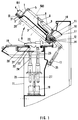
- the bell with pneumatic membrane adapted on a press intended in particular for gluing or the like of strips on a body 7 such as a shoe comprises a support 20 of the body 7, a plate 19 surrounding this support, a hollow cover 1 whose edge has a shape adapted to come into contact with the plate, a flexible membrane 2, and means 4 for securing the edge of the membrane with the cover to define, with the bottom thereof, a closed volume 50.
- the means 4 for securing the edge of the membrane 2 with the cover comprise a clamping flange 3 to trap the edge of the membrane with a complementary part of the cover and means 51 for controlling the movement of the clamping flange 3 relative to the cover 1.
- These means 51 for controlling the movement of the clamping flange relative to the cover are chosen from the following elements: screw, jack.
- the control means 51 are constituted by a plurality of jacks distributed around the cover 1 and actuated for example by a single control button. These cylinders can be of any type, electric, pneumatic, etc.
- the bell further comprises a conduit 52 opening, through one 53 of its ends, into the closed volume 50 and capable of being connected, by its other end 54, to a source of compressed gas (not shown), and means for mounting the cover 1 in displacement relative to the plate 19 so that it can take at least two positions, a first position in which the edge of the cover rests on the plate 19 and a second position in which the edge of the cover is distant of the plate 19.
- the bell further comprises controllable shutter means for the duct 52 making it possible to shut the duct when the cover is substantially in its second position and open it when the cover is substantially in its first position.
- the means for mounting the cover 1 in displacement relative to the plate 19 are constituted by rotation means 14 comprising a fixed shaft with respect to the plate 19 and a bearing integral with the cover 1 and mounted in rotation on the shaft by a friction surface.
- the conduit 52 then comprises a first blind breakthrough made along the axis 12 of the shaft, an orifice connecting this first breakthrough with the side wall of this shaft and being made along an axis substantially perpendicular to the axis 12 of the shaft , a second breakthrough 15 made in the bearing and opening by a first end 53 in the closed volume 50 and by its other second end 16 on the friction surface of the bearing which is pivotally mounted on the shaft, and a pipe portion 57, one end of which is connected to the opening of the first breakthrough and the other end of which constitutes the end 54 of the conduit 52 defined above.
- the controllable means for opening the duct when the cover 1 is substantially in its first position and closing it when it is substantially in its second position are constituted by the fact that the second breakthrough 15 is made in the bearing so that, when the cover 1 is in its first position, its second end 16 is opposite the orifice and that, when the cover is in its second position, the second end 16 of the second breakthrough 15 is not opposite the orifice, the friction surface sealing the outlet of the orifice.
- the bell further comprises controllable means for putting in communication the volume 50 with the ambient medium, with the aim of deflating or at least partially emptying this volume preferably before the cover 1 passes from its first position to the second.
- controllable means for bringing the volume 50 into communication with the ambient environment are advantageously constituted by a valve or the like controlled manually, pneumatically, etc., for example a two-way pneumatic distributor 55 mounted in series on the pipe 52, advantageously on the pipe portion 57.
- a first passway is defined from the end 54 towards the end 53, the second is defined from the end 53 towards the outlet 56 which is a setting to the atmosphere.
- the bell structure described above is advantageous because it makes it possible to prevent the conduit 52 for supplying the volume 50 with compressed gas from being moved at the same time as the cover 1, as would be the case if the conduit opened directly in the volume without passing through the shaft and the bearing.
- this cover is very heavy, it must, as will be mentioned below, that it be balanced during its movements from its first position to the second and vice versa, and it is almost impossible to achieve such balancing with a floating duct, itself very heavy because of its reinforced structure, which leads directly into volume 50.
- This structure also has the following advantage: if the cover 1 is actuated from its first position to the second when, by mistake, the dispenser 55 has not been properly positioned (for example, having remained in its passageway " 54 to 53 "), volume 50 will receive only a small additional quantity of compressed gas. Likewise, it will prevent the volume 50 from receiving compressed gas too soon before the cover 1 has been locked on the plate 19.
- the bell further comprises means for moving the support 20 of the body 7 in a direction substantially perpendicular to the plane of the plate 19 and a stop 9 secured to the cover 1 located in the closed volume 50, this stop being positioned on the path of movement of the support 20 when the cover is in its first position.
- the support 20 is provided with a removable plate 21 defining a lumen 22 intended to receive, for example as illustrated, a shoe 7, the removable plate being placed on a mobile base 23 adjustable vertically by means of example of a bighorn 24 controlled by a motor 25.
- this support 20 may consist of several auxiliary supports, for example two as illustrated in the figures.
- the two auxiliary supports are respectively controlled by two bigornes 24, 26 mounted in parallel and controlled respectively by two motors 25, 27 which, in the case where the body 7 is constituted by a shoe, respectively control the front of the shoe (the bigorne 24) and the heel (bigorne 26).
- the bell also includes means for locking the cover on the tray.
- These means can take different forms.
- One of their possible embodiments has been schematically illustrated in FIGS. 1 and 3. In this case, they consist of at least one hook 28 which hooks onto the plate 19 when the cover 1 is in its closed position. .
- the bell further comprises one or more viewing windows 6 made in the cover 1, which make it possible to see inside the volume 50 after closing the cover 1 and to control, in particular, the positioning of the membrane 2 on the body 7.
- the bell comprises means for controlling the rotation of the cover 1 relative to the plate.
- These means can be constituted, as illustrated in the figures, by a jack 13 of any type, one end of which is connected to the cover 1. In the illustrated embodiment, its other end is connected to the frame 11 of the bell by a rotating member. 35.
- the bell also includes means for balancing the cover in its rotation around the shaft.
- These means can be of any type, for example a spring, a counterweight, etc., and it is recalled that, as the structure described above avoids the presence of a floating duct connected to the cover, the balancing of the cover is easier to carry out and remains constant whatever the position of the cover relative to the tray.
- the bell also comprises, for example, protective screens 17, 18 surrounding the shaft and the rotating bearing, these screens being advantageously secured to the frame 11 of the bell.
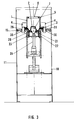
- FIG. 2 represents the pneumatic diaphragm bell when the cover 1 is folded down in the closed position.
- the compressed air is brought through the conduit 52 to the volume 50, the membrane 2 swells and hugs the entire surface of the sole 29 of the shoe 7, the pressure exerted by the membrane allowing the sole to adhere perfectly to the upper of the shoe 7.
- the pressure on the sole is reinforced by means of a stop 9 advantageously fixed on a metal cross member 8 on the upper part 5 of the cover 1.
- This stop serves as a reaction to a booster 10 located at the bottom of the frame 11. It is of an appropriate shape corresponding to that of the sole 29 to be glued on the upper of the shoe.
- FIG. 3 shows a transverse view in which the cover 1 is in the closed position, the membrane 2 applied to the sole 29 of the shoe 7.
- the cover 1 is locked by means of the hooks 28 which adapt through the slots 30 made in tray 19.
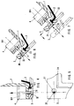
- FIG. 4 In FIG. 4 is shown, in the clamped position, a pneumatic clamping cylinder 51 adapted to the cover 1, allowing instantaneous tightening of the flange 3 energetically pressing the edge of the membrane 2 on the edge of the cover 1 and the rapid change of membrane 2.
- FIG. 5 shows in detail a flat view of part of the clamping flange 3 of the membrane 2, provided with an oblong hole 31 facilitating, by simple displacement of the clamping flange 3, the release of the fixing means 32 of the jack 51 on the clamping flange 3, as well as a groove 34 of suitable shape cooperating with the lower part 36 of the bell to retain the edge of the membrane 2 in the form of molding 33.
- FIG. 6 shows a detail of the pneumatic clamping cylinder 51 representing the fixing means 32 in the released position, the molding 33 of the membrane 2 can then be released from the groove 34 of the clamping flange 3.
- FIG. 7 are shown the different positions of the clamping flange 3 when changing the membrane 2.
- the pneumatic clamping cylinder 51 is in the released position and the clamping flange 3 has been moved, releasing the fixing means 32 through the oblong hole 31.
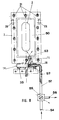
- Figure 8 shows a bottom view of the cover 1 showing the membrane 2 retained by the clamp 3 with the oblong holes 31 allowing the release of the fastening means 32 of the clamp 3, during assembly or disassembly of the membrane 2, as well as the axis of articulation with a means 35 for fixing the bell on the frame 11 and the conduit 52 for the arrival of compressed air inside the closed volume 50 closed at 16 to ensure a greater security, the air thus being able to enter the closed volume only when the cover 1 is locked on the plate 19 by means of the hooks 28.
Landscapes
- Footwear And Its Accessory, Manufacturing Method And Apparatuses (AREA)
- Actuator (AREA)
- Tents Or Canopies (AREA)
Abstract
Description
La présente invention concerne les cloches à membrane pneumatique adaptée sur une presse destinée notamment au collage ou analogue de bandes sur un corps comme, par exemple mais non exclusivement, les semelles sur des chaussures ou analogues.The present invention relates to pneumatic diaphragm bells adapted to a press intended in particular for bonding or the like to strips on a body such as, for example but not exclusively, the soles on shoes or the like.
On connaît déjà de telles cloches, par exemple celles qui sont décrites et illustrées dans les GB-A-2 151 904, DE-A-35 16 577 et EP-A-0 141 183.Such bells are already known, for example those which are described and illustrated in GB-A-2 151 904, DE-A-35 16 577 and EP-A-0 141 183.
Cependant, la présente invention a pour but de réaliser une cloche à membrane pneumatique adaptée sur une presse destinée notamment au collage ou analogue de bandes sur des corps comme des chaussures, qui présente une plus grande sécurité de fonctionnement que les cloches connues de l'art antérieur.However, the object of the present invention is to produce a bell with a pneumatic membrane suitable for a press intended in particular for gluing or the like of strips on bodies such as shoes, which has greater operating safety than the bells known in the art. prior.
Plus précisément, la présente invention a pour objet une cloche à membrane pneumatique adaptée sur une presse destinée notamment au collage ou analogue de bandes sur un corps, comportant:
- un support dudit corps,
- un plateau entourant ledit support,
- un couvercle en creux dont le bord présente une forme adaptée pour venir au contact dudit plateau,
- une membrane souple,
- des moyens pour solidariser la bordure de ladite membrane avec ledit couvercle pour définir, avec le fond de celui-ci, un volume fermé,
- un conduit débouchant par une extrémité dans ledit volume fermé et apte à être connecté, par son autre extrémité, à une source de gaz comprimé,
- des moyens pour monter ledit couvercle en déplacement par rapport audit plateau de façon qu'il puisse prendre au moins deux positions, une première position dans laquelle le bord dudit couvercle repose sur ledit plateau et une seconde position dans laquelle le bord dudit couvercle est éloigné dudit plateau, caractérisée par le fait qu'elle comporte en outre des moyens d'obturation commandables permettant d'obturer ledit conduit quand le couvercle est sensiblement dans sa seconde position et de l'ouvrir lorsque le couvercle est sensiblement dans sa première position.
- a support for said body,
- a tray surrounding said support,
- a hollow cover, the edge of which has a shape suitable for coming into contact with said tray,
- a flexible membrane,
- means for securing the edge of said membrane with said cover to define, with the bottom thereof, a closed volume,
- a conduit opening at one end into said closed volume and capable of being connected, at its other end, to a source of compressed gas,
- means for mounting said cover in displacement with respect to said tray so that it can take at least two positions, a first position in which the edge of said cover rests on said tray and a second position in which the edge of said cover is remote from said tray, characterized in that it further comprises controllable closure means making it possible to close said duct when the cover is substantially in its second position and to open it when the cover is substantially in its first position.
D'autres caractéristiques et avantages de la présente invention apparaîtront au cours de la description suivante donnée en regard des dessins annexés à titre illustratif, mais nullement limitatif, dans lesquels:
- La figure 1 représente, en coupe, une vue de côté d'une cloche selon l'invention à membrane pneumatique adaptée sur une presse, dans une application au collage d'une semelle sur une chaussure, ladite cloche étant représentée avec le couvercle en position relevée pour permettre le positionnement de la chaussure,
- La figure 2 représente, en coupe, une vue de côté de la cloche selon la figure 1, mais avec le couvercle en position rabattue dite "de travail",
- La figure 3 représente une coupe transversale de la cloche en position de travail,
- La figure 4 représente un vérin de bridage en position serrée,
- La figure 5 représente en détail une vue à plat d'une partie de la bride de serrage,
- La figure 6 représente le vérin de serrage en position de desserrage pour le changement de la membrane, le couvercle étant en position relevée,
- La figure 7 représente les différents positionnements de la bride de serrage lors du changement de la membrane, et
- La figure 8 représente une vue de dessous de la cloche, montrant la membrane retenue par la bride de serrage ainsi que l'axe d'articulation et le moyen de fixation de la cloche sur la presse.
- FIG. 1 represents, in section, a side view of a bell according to the invention with a pneumatic membrane adapted on a press, in an application to the bonding of a sole on a shoe, said bell being shown with the cover in raised position to allow the positioning of the shoe,
- FIG. 2 represents, in section, a side view of the bell according to FIG. 1, but with the cover in the folded down position called "working",
- FIG. 3 represents a cross section of the bell in the working position,
- FIG. 4 represents a clamping cylinder in the tight position,
- FIG. 5 shows in detail a flat view of part of the clamping flange,
- FIG. 6 shows the clamping cylinder in the loosening position for changing the membrane, the cover being in the raised position,
- FIG. 7 shows the different positions of the clamp when changing the membrane, and
- Figure 8 shows a bottom view of the bell, showing the membrane retained by the clamp as well as the hinge pin and the means for fixing the bell on the press.
Les huit figures représentent un même mode de réalisation d'une cloche à membrane pneumatique adaptée sur une presse, selon l'invention. En conséquence les mêmes références y désignent les mêmes éléments, quelle que soit la figure sur laquelle elles apparaissent.The eight figures show the same embodiment of a pneumatic membrane bell adapted to a press, according to the invention. Consequently, the same references designate the same elements there, whatever the figure on which they appear.
La cloche à membrane pneumatique adaptée sur une presse destinée notamment au collage ou analogue de bandes sur un corps 7 comme une chaussure, comporte un support 20 du corps 7, un plateau 19 entourant ce support, un couvercle en creux 1 dont le bord présente une forme adaptée pour venir au contact du plateau, une membrane souple 2, et des moyens 4 pour solidariser la bordure de la membrane avec le couvercle pour définir, avec le fond de celui-ci, un volume fermé 50.The bell with pneumatic membrane adapted on a press intended in particular for gluing or the like of strips on a
Dans un mode de réalisation avantageux, les moyens 4 pour solidariser la bordure de la membrane 2 avec le couvercle comportent une bride de serrage 3 pour emprisonner la bordure de la membrane avec une partie complémentaire du couvercle et des moyens 51 pour commander le déplacement de la bride de serrage 3 par rapport au couvercle 1. Ces moyens 51 pour commander le déplacement de la bride de serrage par rapport au couvercle sont choisis parmi les éléments suivants: vis, vérin. Dans le mode de réalisation illustré, les moyens de commande 51 sont constitués par une pluralité de vérins répartis autour du couvercle 1 et actionnés par exemple par un bouton de commande unique. Ces vérins peuvent être de tout type, électrique, pneumatique, etc.In an advantageous embodiment, the
La cloche comporte en outre un conduit 52 débouchant, par l'une 53 de ses extrémités, dans le volume fermé 50 et apte à être connecté, par son autre extrémité 54, à une source de gaz comprimé (non représentée), et des moyens pour monter le couvercle 1 en déplacement par rapport au plateau 19 de façon qu'il puisse prendre au moins deux positions, une première position dans laquelle le bord du couvercle repose sur le plateau 19 et une seconde position dans laquelle le bord du couvercle est éloigné du plateau 19.The bell further comprises a
Selon une caractéristique importante de l'invention visant à atteindre le but défini dans le préambule de la présente description, la cloche comporte en outre des moyens d'obturation commandables du conduit 52 permettant d'obturer le conduit quand le couvercle est sensiblement dans sa seconde position et de l'ouvrir lorsque le couvercle est sensiblement dans sa première position.According to an important characteristic of the invention aimed at achieving the aim defined in the preamble of this description, the bell further comprises controllable shutter means for the
Dans un mode de réalisation avantageux, les moyens pour monter le couvercle 1 en déplacement par rapport au plateau 19 sont constitués par des moyens de rotation 14 comportant un arbre fixe par rapport au plateau 19 et un palier solidaire du couvercle 1 et monté en rotation sur l'arbre par une surface de friction.In an advantageous embodiment, the means for mounting the cover 1 in displacement relative to the
Le conduit 52 comporte alors une première percée borgne réalisée selon l'axe 12 de l'arbre, un orifice reliant cette première percée avec la paroi latérale de cet arbre et étant réalisé suivant un axe sensiblement perpendiculaire à l'axe 12 de l'arbre, une seconde percée 15 réalisée dans le palier et débouchant par une première extrémité 53 dans le volume fermé 50 et par son autre seconde extrémité 16 sur la surface de friction du palier qui est monté en pivotement sur l'arbre, et une portion de conduite 57 dont une extrémité est reliée à l'ouverture de la première percée et dont l'autre extrémité constitue l'extrémité 54 du conduit 52 définie ci-avant.The
Les moyens commandables pour ouvrir le conduit quand le couvercle 1 est sensiblement dans sa première position et l'obturer lorsqu'il est sensiblement dans sa seconde position, sont constitués par le fait que la seconde percée 15 est réalisée dans le palier de façon que, lorsque le couvercle 1 est dans sa première position, sa seconde extrémité 16 soit en regard de l'orifice et que, lorsque le couvercle est dans sa seconde position, la seconde extrémité 16 de la seconde percée 15 ne soit pas en regard de l'orifice, la surface de friction obturant la sortie de l'orifice.The controllable means for opening the duct when the cover 1 is substantially in its first position and closing it when it is substantially in its second position, are constituted by the fact that the
La cloche comporte en outre des moyens commandables pour mettre en communication le volume 50 avec le milieu ambiant, dans le but de dégonfler ou vider au moins partiellement ce volume de préférence avant que le couvercle 1 ne passe de sa première position à la seconde.The bell further comprises controllable means for putting in communication the
Dans le mode de réalisation illustré sur la figure 8, les moyens commandables pour mettre en communication le volume 50 avec le milieu ambiant sont avantageusement constitués par une vanne ou analogue commandée manuellement, pneumatiquement, etc., par exemple un distributeur pneumatique 55 à deux voies monté en série sur le conduit 52, avantageusement sur la portion de conduite 57. Une première voie passante est définie de l'extrémité 54 vers l'extrémité 53, la seconde est définie de l'extrémité 53 vers la sortie 56 qui est une mise à l'atmosphère.In the embodiment illustrated in FIG. 8, the controllable means for bringing the
La structure de cloche décrite ci-dessus est avantageuse car elle permet d'éviter que le conduit 52 d'alimentation du volume 50 en gaz comprimé ne soit déplacé en même temps que le couvercle 1, comme ce serait le cas si le conduit débouchait directement dans le volume sans passer par l'arbre et le palier. En effet, comme ce couvercle est très lourd, il faut, comme il sera mentionné ci-après, qu'il soit équilibré pendant ses déplacements de sa première position à la seconde et inversement, et il est presque impossible de réaliser un tel équilibrage avec un conduit flottant, lui-même très lourd à cause de sa structure renforcée, qui débouche directement dans le volume 50.The bell structure described above is advantageous because it makes it possible to prevent the
Cette structure présente également l'avantage suivant: si le couvercle 1 est actionné de sa première position à la seconde alors que, par erreur, le distributeur 55 n'a pas bien été positionné (en étant resté par exemple dans sa voie de passage "54 vers 53"), le volume 50 ne recevra qu'une faible quantité supplémentaire de gaz comprimé. De même, elle évitera que le volume 50 ne reçoive trop tôt du gaz comprimé avant que le couvercle 1 n'ait été verrouillé sur le plateau 19.This structure also has the following advantage: if the cover 1 is actuated from its first position to the second when, by mistake, the
Dans une réalisation avantageuse, la cloche comporte en outre des moyens pour déplacer le support 20 du corps 7 suivant une direction sensiblement perpendiculaire au plan du plateau 19 et une butée 9 solidaire du couvercle 1 située dans le volume fermé 50, cette butée étant positionnée sur le trajet de déplacement du support 20 quand le couvercle est dans sa première position. Dans le mode de réalisation illustré, le support 20 est muni d'une plaque amovible 21 définissant une lumière 22 destinée à recevoir, par exemple comme illustré, une chaussure 7, la plaque amovible étant posée sur une embase mobile 23 réglable verticalement au moyen par exemple d'une bigorne 24 commandée par un moteur 25.In an advantageous embodiment, the bell further comprises means for moving the
Dans une réalisation avantageuse, ce support 20 peut être constitué de plusieurs supports auxiliaires, par exemple deux comme illustré sur les figures. Les deux supports auxiliaires sont respectivement commandés par deux bigornes 24, 26 montées en parallèle et commandées respectivement par deux moteurs 25, 27 qui, dans le cas où le corps 7 est constitué par une chaussure, commandent respectivement l'avant de la chaussure (la bigorne 24) et le talon (la bigorne 26).In an advantageous embodiment, this
Dans le but principal annoncé dans le préambule de la présente description, il est avantageux que la cloche comporte aussi des moyens pour verrouiller le couvercle sur le plateau. Ces moyens peuvent prendre différentes formes. L'un de leurs modes de réalisation possibles a été schématiquement illustré sur les figures 1 et 3. Ils sont dans ce cas constitués par au moins un crochet 28 qui vient s'accrocher sur le plateau 19 quand le couvercle 1 est dans sa position fermée.For the main purpose announced in the preamble to this description, it is advantageous that the bell also includes means for locking the cover on the tray. These means can take different forms. One of their possible embodiments has been schematically illustrated in FIGS. 1 and 3. In this case, they consist of at least one
De façon préférentielle, la cloche comporte en outre un ou plusieurs hublots de vision 6 réalisés dans le couvercle 1, qui permettent de voir dans l'intérieur du volume 50 après fermeture du couvercle 1 et de contrôler, notamment, le positionnement de la membrane 2 sur le corps 7.Preferably, the bell further comprises one or more viewing windows 6 made in the cover 1, which make it possible to see inside the
Bien entendu, le couvercle doit pouvoir passer de l'une de ses positions à l'autre de façon aisée. Dans ce but, la cloche comporte des moyens pour commander la rotation du couvercle 1 par rapport au plateau. Ces moyens peuvent être constitués, comme illustré sur les figures, par un vérin 13 de tout type dont une extrémité est reliée au couvercle 1. Dans le mode de réalisation illustré, son autre extrémité est reliée au bâti 11 de la cloche par un organe tournant 35.Of course, the cover must be able to pass from one of its positions to the other easily. For this purpose, the bell comprises means for controlling the rotation of the cover 1 relative to the plate. These means can be constituted, as illustrated in the figures, by a
De façon avantageuse, la cloche comporte aussi des moyens pour équilibrer le couvercle dans sa rotation autour de l'arbre. Ces moyens peuvent être de tout type, par exemple un ressort, un contrepoids, etc., et il est rappelé que, comme la structure décrite ci-dessus évite la présence d'un conduit flottant relié au couvercle, l'équilibrage du couvercle est plus facile à réaliser et reste constant quelle que soit la position du couvercle par rapport au plateau. Accessoirement, la cloche comporte aussi, par exemple, des écrans protecteurs 17, 18 entourant l'arbre et le palier tournant, ces écrans étant avantageusement solidarisés au bâti 11 de la cloche.Advantageously, the bell also includes means for balancing the cover in its rotation around the shaft. These means can be of any type, for example a spring, a counterweight, etc., and it is recalled that, as the structure described above avoids the presence of a floating duct connected to the cover, the balancing of the cover is easier to carry out and remains constant whatever the position of the cover relative to the tray. Incidentally, the bell also comprises, for example,
La figure 2 représente la cloche à membrane pneumatique lorsque le couvercle 1 est rabattu en position fermée. L'air comprimé est amené par le conduit 52 jusqu'au volume 50, la membrane 2 se gonfle et épouse toute la surface de la semelle 29 de la chaussure 7, la pression exercée par la membrane permettant à la semelle d'adhérer parfaitement à l'empeigne de la chaussure 7. La pression sur la semelle est renforcée au moyen d'une butée 9 fixée avantageusement sur une traverse métallique 8 sur la partie supérieure 5 du couvercle 1. Cette butée sert de réaction à un surpresseur 10 situé au bas du bâti 11. Elle est d'une forme appropriée correspondant à celle de la semelle 29 à coller sur l'empeigne de la chaussure.FIG. 2 represents the pneumatic diaphragm bell when the cover 1 is folded down in the closed position. The compressed air is brought through the
La figure 3 montre une vue transversale dans laquelle le couvercle 1 est en position fermée, la membrane 2 appliquée sur la semelle 29 de la chaussure 7. Le couvercle 1 est verrouillé au moyen des crochets 28 venant s'adapter à travers les lumières 30 réalisées dans le plateau 19.FIG. 3 shows a transverse view in which the cover 1 is in the closed position, the
Sur la figure 4, est représenté, en position serrée, un vérin pneumatique de bridage 51 adapté au couvercle 1, permettant le serrage instantané de la bride 3 plaquant énergiquement la bordure de la membrane 2 sur le bord du couvercle 1 et le changement rapide de la membrane 2.In FIG. 4 is shown, in the clamped position, a
La figure 5 représente en détail une vue à plat d'une partie de la bride de serrage 3 de la membrane 2, munie d'un trou oblong 31 facilitant, par simple déplacement de la bride de serrage 3, le dégagement du moyen de fixation 32 du vérin 51 sur la bride de serrage 3, ainsi qu'une gorge 34 de forme appropriée coopérant avec la partie inférieure 36 de la cloche pour retenir la bordure de la membrane 2 en forme de moulure 33.FIG. 5 shows in detail a flat view of part of the clamping
La figure 6 représente un détail du vérin pneumatique de bridage 51 représentant le moyen de fixation 32 en position desserrée, la moulure 33 de la membrane 2 pouvant alors être dégagée de la gorge 34 de la bride de serrage 3.FIG. 6 shows a detail of the
Sur la figure 7 sont représentés les différents positionnements de la bride de serrage 3 lors du changement de membrane 2. Le vérin pneumatique de bridage 51 est en position desserrée et la bride de serrage 3 a été déplacée, libérant le moyen de fixation 32 à travers le trou oblong 31.In FIG. 7 are shown the different positions of the clamping
La figure 8 représente une vue de dessous du couvercle 1 faisant apparaître la membrane 2 retenue par la bride de serrage 3 avec les trous oblongs 31 permettant le dégagement des moyens de fixation 32 de la bride de serrage 3, lors du montage ou du démontage de la membrane 2, ainsi que l'axe d'articulation avec un moyen de fixation 35 de la cloche sur le bâti 11 et le conduit 52 d'arrivée d'air comprimé à l'intérieur du volume fermé 50 obturé en 16 pour assurer une plus grande sécurité, l'air ne pouvant ainsi pénétrer dans le volume fermé que lorsque le couvercle 1 est verrouillé sur le plateau 19 au moyen des crochets 28.Figure 8 shows a bottom view of the cover 1 showing the
Claims (10)
Applications Claiming Priority (2)
| Application Number | Priority Date | Filing Date | Title |
|---|---|---|---|
| FR9502801 | 1995-03-10 | ||
| FR9502801A FR2731327B1 (en) | 1995-03-10 | 1995-03-10 | PNEUMATIC MEMBRANE BELL ADAPTED TO A PRESS INTENDED IN PARTICULAR FOR BONDING SOLE ON SHOES |
Publications (2)
| Publication Number | Publication Date |
|---|---|
| EP0730833A1 true EP0730833A1 (en) | 1996-09-11 |
| EP0730833B1 EP0730833B1 (en) | 2000-09-20 |
Family
ID=9476926
Family Applications (1)
| Application Number | Title | Priority Date | Filing Date |
|---|---|---|---|
| EP19960400465 Expired - Lifetime EP0730833B1 (en) | 1995-03-10 | 1996-03-05 | Pneumatic membrane-type press |
Country Status (4)
| Country | Link |
|---|---|
| EP (1) | EP0730833B1 (en) |
| DE (1) | DE69610344D1 (en) |
| ES (1) | ES2151134T3 (en) |
| FR (1) | FR2731327B1 (en) |
Cited By (4)
| Publication number | Priority date | Publication date | Assignee | Title |
|---|---|---|---|---|
| FR2839862A1 (en) | 2002-05-24 | 2003-11-28 | Tech Et Realisations Mecanique | Machine for sticking the sole of a shoe on a shoe upper has table with opening in it and a translatably movable support that moves in opposition to two edges that translatably move w.r.t opening perpendicular to support movement |
| CN102293484A (en) * | 2011-08-31 | 2011-12-28 | 吴江源兴工艺鞋业有限公司 | Shoe edge pressing machine |
| KR20220106847A (en) * | 2017-11-22 | 2022-07-29 | 나이키 이노베이트 씨.브이. | Conforming membrane for manufacturing footwear |
| IT202200023781A1 (en) * | 2022-11-17 | 2024-05-17 | Irocol S R L | MEMBRANE PRESS FOR FOOTWEAR BONDING. |
Families Citing this family (1)
| Publication number | Priority date | Publication date | Assignee | Title |
|---|---|---|---|---|
| FR2754683B1 (en) * | 1996-10-18 | 1998-11-27 | Salomon Sa | PRESSING METHOD AND DEVICE FOR ASSEMBLING BY GLUING A SOLE WITH A SHOE SHOE |
Citations (3)
| Publication number | Priority date | Publication date | Assignee | Title |
|---|---|---|---|---|
| EP0141183A2 (en) * | 1983-10-25 | 1985-05-15 | Herbert Dr.-Ing. Funck | Glueing press for shoes |
| GB2151904A (en) * | 1983-12-01 | 1985-07-31 | Quiles D Pascual Sansano | Machine for attaching soles to footwear |
| DE3516577A1 (en) * | 1985-05-08 | 1986-11-13 | Herbert Dr.-Ing. 8032 Gräfelfing Funck | Bonding press for bonding shoe soles onto lasted-on upper shoes |
-
1995
- 1995-03-10 FR FR9502801A patent/FR2731327B1/en not_active Expired - Fee Related
-
1996
- 1996-03-05 EP EP19960400465 patent/EP0730833B1/en not_active Expired - Lifetime
- 1996-03-05 ES ES96400465T patent/ES2151134T3/en not_active Expired - Lifetime
- 1996-03-05 DE DE69610344T patent/DE69610344D1/en not_active Expired - Lifetime
Patent Citations (3)
| Publication number | Priority date | Publication date | Assignee | Title |
|---|---|---|---|---|
| EP0141183A2 (en) * | 1983-10-25 | 1985-05-15 | Herbert Dr.-Ing. Funck | Glueing press for shoes |
| GB2151904A (en) * | 1983-12-01 | 1985-07-31 | Quiles D Pascual Sansano | Machine for attaching soles to footwear |
| DE3516577A1 (en) * | 1985-05-08 | 1986-11-13 | Herbert Dr.-Ing. 8032 Gräfelfing Funck | Bonding press for bonding shoe soles onto lasted-on upper shoes |
Cited By (4)
| Publication number | Priority date | Publication date | Assignee | Title |
|---|---|---|---|---|
| FR2839862A1 (en) | 2002-05-24 | 2003-11-28 | Tech Et Realisations Mecanique | Machine for sticking the sole of a shoe on a shoe upper has table with opening in it and a translatably movable support that moves in opposition to two edges that translatably move w.r.t opening perpendicular to support movement |
| CN102293484A (en) * | 2011-08-31 | 2011-12-28 | 吴江源兴工艺鞋业有限公司 | Shoe edge pressing machine |
| KR20220106847A (en) * | 2017-11-22 | 2022-07-29 | 나이키 이노베이트 씨.브이. | Conforming membrane for manufacturing footwear |
| IT202200023781A1 (en) * | 2022-11-17 | 2024-05-17 | Irocol S R L | MEMBRANE PRESS FOR FOOTWEAR BONDING. |
Also Published As
| Publication number | Publication date |
|---|---|
| EP0730833B1 (en) | 2000-09-20 |
| ES2151134T3 (en) | 2000-12-16 |
| DE69610344D1 (en) | 2000-10-26 |
| FR2731327A1 (en) | 1996-09-13 |
| FR2731327B1 (en) | 1997-05-23 |
Similar Documents
| Publication | Publication Date | Title |
|---|---|---|
| EP0547925B1 (en) | Control device for the dispensing of a product, especially a foaming mousse product | |
| CH407876A (en) | Mobile air knife transport | |
| FR2720733A1 (en) | Filling device comprising a cleaning manifold fixed to a distribution duct. | |
| FR2475105A1 (en) | MECHANISM FORMING HINGE FOR AUTOMOTIVE VEHICLE TRUNK COVER | |
| FR2480692A1 (en) | CONTROL DEVICE FOR THE VALVE MECHANISM OF A SERVOFREIN | |
| FR2791338A1 (en) | CONTAINER FILLING DEVICE HAVING AN INTEGRATED CLEANING DEVICE | |
| FR2543024A1 (en) | DISPENSING DEVICE IN THE FORM OF A SUCTION PISTOL | |
| EP0730833A1 (en) | Pneumatic membrane-type press | |
| FR2540450A1 (en) | DEPRESSION BRAKE AMPLIFIER FOR MOTOR VEHICLE | |
| EP0760306B1 (en) | Tank inlet cover | |
| FR2539329A1 (en) | PRESSURE REGULATION DROPPER DISPENSER | |
| FR2781550A1 (en) | METHOD FOR CHANGING A FILTER CARTRIDGE MOUNTED IN A FLUID FLOW CONDUIT AND ARRANGEMENT FOR IMPLEMENTING THE METHOD | |
| FR2786304A3 (en) | Advertising holder with inflatable sleeve and pressurized air generator | |
| FR2528517A1 (en) | SHUTTER FOR MOUNTING INTO A BODY | |
| FR2721871A1 (en) | PROJECTOR WITH PLATE CORRECTOR, PARTICULARLY FOR MOTOR VEHICLE, INTERMEDIATE MOUNTING PART AND SUB-ASSEMBLY FOR SUCH A PROJECTOR | |
| EP1405796B1 (en) | Fluid dispensing apparatus | |
| EP0778111B1 (en) | Emergency stopping module for a robot | |
| EP0867570A1 (en) | Flushing cistern for recessed mounting operated at the top or at the front | |
| EP1134341B1 (en) | Articulated door system for vehicles, containers and similar | |
| EP1647419B1 (en) | Ejector for granular material | |
| EP1032512A1 (en) | Device for controlling dome light illumination | |
| FR2846108A1 (en) | Jack assembly for raising lid of building ventilation outlet, comprises support with lateral jack pivot, jack rod with tip to engage lid block and bolted plate on jack rod to align tip when retracted | |
| FR2467419A1 (en) | PHOTOGRAPHIC REPRODUCTION DEVICE THROUGH A CONTACT METHOD | |
| CA2532016A1 (en) | Folding door and shutter guide device | |
| EP0146435B1 (en) | Device for turning the pages of a book |
Legal Events
| Date | Code | Title | Description |
|---|---|---|---|
| PUAI | Public reference made under article 153(3) epc to a published international application that has entered the european phase |
Free format text: ORIGINAL CODE: 0009012 |
|
| AK | Designated contracting states |
Kind code of ref document: A1 Designated state(s): BE DE ES FR GB GR IT NL PT |
|
| 17P | Request for examination filed |
Effective date: 19970228 |
|
| 17Q | First examination report despatched |
Effective date: 19990305 |
|
| GRAG | Despatch of communication of intention to grant |
Free format text: ORIGINAL CODE: EPIDOS AGRA |
|
| GRAG | Despatch of communication of intention to grant |
Free format text: ORIGINAL CODE: EPIDOS AGRA |
|
| GRAH | Despatch of communication of intention to grant a patent |
Free format text: ORIGINAL CODE: EPIDOS IGRA |
|
| GRAH | Despatch of communication of intention to grant a patent |
Free format text: ORIGINAL CODE: EPIDOS IGRA |
|
| GRAA | (expected) grant |
Free format text: ORIGINAL CODE: 0009210 |
|
| AK | Designated contracting states |
Kind code of ref document: B1 Designated state(s): BE DE ES FR GB GR IT NL PT |
|
| PG25 | Lapsed in a contracting state [announced via postgrant information from national office to epo] |
Ref country code: NL Free format text: LAPSE BECAUSE OF FAILURE TO SUBMIT A TRANSLATION OF THE DESCRIPTION OR TO PAY THE FEE WITHIN THE PRESCRIBED TIME-LIMIT Effective date: 20000920 Ref country code: GR Free format text: LAPSE BECAUSE OF NON-PAYMENT OF DUE FEES Effective date: 20000920 Ref country code: GB Free format text: LAPSE BECAUSE OF FAILURE TO SUBMIT A TRANSLATION OF THE DESCRIPTION OR TO PAY THE FEE WITHIN THE PRESCRIBED TIME-LIMIT Effective date: 20000920 |
|
| REF | Corresponds to: |
Ref document number: 69610344 Country of ref document: DE Date of ref document: 20001026 |
|
| ITF | It: translation for a ep patent filed | ||
| REG | Reference to a national code |
Ref country code: ES Ref legal event code: FG2A Ref document number: 2151134 Country of ref document: ES Kind code of ref document: T3 |
|
| PG25 | Lapsed in a contracting state [announced via postgrant information from national office to epo] |
Ref country code: PT Free format text: LAPSE BECAUSE OF FAILURE TO SUBMIT A TRANSLATION OF THE DESCRIPTION OR TO PAY THE FEE WITHIN THE PRESCRIBED TIME-LIMIT Effective date: 20001220 |
|
| PG25 | Lapsed in a contracting state [announced via postgrant information from national office to epo] |
Ref country code: DE Free format text: LAPSE BECAUSE OF FAILURE TO SUBMIT A TRANSLATION OF THE DESCRIPTION OR TO PAY THE FEE WITHIN THE PRESCRIBED TIME-LIMIT Effective date: 20001221 |
|
| NLV1 | Nl: lapsed or annulled due to failure to fulfill the requirements of art. 29p and 29m of the patents act | ||
| GBV | Gb: ep patent (uk) treated as always having been void in accordance with gb section 77(7)/1977 [no translation filed] |
Effective date: 20000920 |
|
| PG25 | Lapsed in a contracting state [announced via postgrant information from national office to epo] |
Ref country code: BE Free format text: LAPSE BECAUSE OF NON-PAYMENT OF DUE FEES Effective date: 20010331 |
|
| PLBE | No opposition filed within time limit |
Free format text: ORIGINAL CODE: 0009261 |
|
| STAA | Information on the status of an ep patent application or granted ep patent |
Free format text: STATUS: NO OPPOSITION FILED WITHIN TIME LIMIT |
|
| 26N | No opposition filed | ||
| BERE | Be: lapsed |
Owner name: SOC. D'ETUDES TECHNIQUES ET REALISATIONS MECANIQUE Effective date: 20010331 |
|
| PGFP | Annual fee paid to national office [announced via postgrant information from national office to epo] |
Ref country code: ES Payment date: 20070315 Year of fee payment: 12 |
|
| PGFP | Annual fee paid to national office [announced via postgrant information from national office to epo] |
Ref country code: IT Payment date: 20070622 Year of fee payment: 12 |
|
| PGFP | Annual fee paid to national office [announced via postgrant information from national office to epo] |
Ref country code: FR Payment date: 20070326 Year of fee payment: 12 |
|
| REG | Reference to a national code |
Ref country code: FR Ref legal event code: ST Effective date: 20081125 |
|
| PG25 | Lapsed in a contracting state [announced via postgrant information from national office to epo] |
Ref country code: FR Free format text: LAPSE BECAUSE OF NON-PAYMENT OF DUE FEES Effective date: 20080331 |
|
| REG | Reference to a national code |
Ref country code: ES Ref legal event code: FD2A Effective date: 20080306 |
|
| PG25 | Lapsed in a contracting state [announced via postgrant information from national office to epo] |
Ref country code: ES Free format text: LAPSE BECAUSE OF NON-PAYMENT OF DUE FEES Effective date: 20080306 |
|
| PG25 | Lapsed in a contracting state [announced via postgrant information from national office to epo] |
Ref country code: IT Free format text: LAPSE BECAUSE OF NON-PAYMENT OF DUE FEES Effective date: 20080305 |