EP0729117B1 - Méthode et arrangement pour la détection des positions de changement dans des images animées - Google Patents
Méthode et arrangement pour la détection des positions de changement dans des images animées Download PDFInfo
- Publication number
- EP0729117B1 EP0729117B1 EP96102603A EP96102603A EP0729117B1 EP 0729117 B1 EP0729117 B1 EP 0729117B1 EP 96102603 A EP96102603 A EP 96102603A EP 96102603 A EP96102603 A EP 96102603A EP 0729117 B1 EP0729117 B1 EP 0729117B1
- Authority
- EP
- European Patent Office
- Prior art keywords
- frame
- change
- video
- point
- correlation coefficient
- Prior art date
- Legal status (The legal status is an assumption and is not a legal conclusion. Google has not performed a legal analysis and makes no representation as to the accuracy of the status listed.)
- Expired - Lifetime
Links
- 230000008859 change Effects 0.000 title claims description 158
- 238000000034 method Methods 0.000 title claims description 37
- 238000012545 processing Methods 0.000 claims description 36
- 238000004590 computer program Methods 0.000 claims description 31
- 230000002045 lasting effect Effects 0.000 claims description 5
- 238000004513 sizing Methods 0.000 claims 3
- 238000001514 detection method Methods 0.000 description 26
- 230000033001 locomotion Effects 0.000 description 12
- 230000000875 corresponding effect Effects 0.000 description 10
- 238000010586 diagram Methods 0.000 description 9
- 230000008569 process Effects 0.000 description 5
- 238000004364 calculation method Methods 0.000 description 4
- 230000004044 response Effects 0.000 description 4
- 239000003086 colorant Substances 0.000 description 3
- 238000007796 conventional method Methods 0.000 description 3
- 230000000694 effects Effects 0.000 description 2
- 230000006870 function Effects 0.000 description 2
- 230000008901 benefit Effects 0.000 description 1
- 239000000470 constituent Substances 0.000 description 1
- 230000002596 correlated effect Effects 0.000 description 1
- 230000007423 decrease Effects 0.000 description 1
- 230000000593 degrading effect Effects 0.000 description 1
- 238000010304 firing Methods 0.000 description 1
- 230000010365 information processing Effects 0.000 description 1
- 238000004519 manufacturing process Methods 0.000 description 1
- 238000012986 modification Methods 0.000 description 1
- 230000004048 modification Effects 0.000 description 1
- 230000003287 optical effect Effects 0.000 description 1
- 230000004800 psychological effect Effects 0.000 description 1
- 230000009467 reduction Effects 0.000 description 1
- 230000000630 rising effect Effects 0.000 description 1
- 238000011896 sensitive detection Methods 0.000 description 1
- 230000035945 sensitivity Effects 0.000 description 1
- 238000012360 testing method Methods 0.000 description 1
- 230000007704 transition Effects 0.000 description 1
Images


Classifications
-
- G—PHYSICS
- G06—COMPUTING; CALCULATING OR COUNTING
- G06T—IMAGE DATA PROCESSING OR GENERATION, IN GENERAL
- G06T7/00—Image analysis
- G06T7/20—Analysis of motion
- G06T7/246—Analysis of motion using feature-based methods, e.g. the tracking of corners or segments
-
- G—PHYSICS
- G06—COMPUTING; CALCULATING OR COUNTING
- G06F—ELECTRIC DIGITAL DATA PROCESSING
- G06F16/00—Information retrieval; Database structures therefor; File system structures therefor
- G06F16/70—Information retrieval; Database structures therefor; File system structures therefor of video data
- G06F16/74—Browsing; Visualisation therefor
- G06F16/745—Browsing; Visualisation therefor the internal structure of a single video sequence
-
- G—PHYSICS
- G06—COMPUTING; CALCULATING OR COUNTING
- G06F—ELECTRIC DIGITAL DATA PROCESSING
- G06F16/00—Information retrieval; Database structures therefor; File system structures therefor
- G06F16/70—Information retrieval; Database structures therefor; File system structures therefor of video data
- G06F16/78—Retrieval characterised by using metadata, e.g. metadata not derived from the content or metadata generated manually
- G06F16/783—Retrieval characterised by using metadata, e.g. metadata not derived from the content or metadata generated manually using metadata automatically derived from the content
- G06F16/7834—Retrieval characterised by using metadata, e.g. metadata not derived from the content or metadata generated manually using metadata automatically derived from the content using audio features
-
- G—PHYSICS
- G06—COMPUTING; CALCULATING OR COUNTING
- G06F—ELECTRIC DIGITAL DATA PROCESSING
- G06F16/00—Information retrieval; Database structures therefor; File system structures therefor
- G06F16/70—Information retrieval; Database structures therefor; File system structures therefor of video data
- G06F16/78—Retrieval characterised by using metadata, e.g. metadata not derived from the content or metadata generated manually
- G06F16/783—Retrieval characterised by using metadata, e.g. metadata not derived from the content or metadata generated manually using metadata automatically derived from the content
- G06F16/7847—Retrieval characterised by using metadata, e.g. metadata not derived from the content or metadata generated manually using metadata automatically derived from the content using low-level visual features of the video content
- G06F16/785—Retrieval characterised by using metadata, e.g. metadata not derived from the content or metadata generated manually using metadata automatically derived from the content using low-level visual features of the video content using colour or luminescence
-
- G—PHYSICS
- G11—INFORMATION STORAGE
- G11B—INFORMATION STORAGE BASED ON RELATIVE MOVEMENT BETWEEN RECORD CARRIER AND TRANSDUCER
- G11B27/00—Editing; Indexing; Addressing; Timing or synchronising; Monitoring; Measuring tape travel
- G11B27/02—Editing, e.g. varying the order of information signals recorded on, or reproduced from, record carriers
- G11B27/031—Electronic editing of digitised analogue information signals, e.g. audio or video signals
- G11B27/034—Electronic editing of digitised analogue information signals, e.g. audio or video signals on discs
-
- G—PHYSICS
- G11—INFORMATION STORAGE
- G11B—INFORMATION STORAGE BASED ON RELATIVE MOVEMENT BETWEEN RECORD CARRIER AND TRANSDUCER
- G11B27/00—Editing; Indexing; Addressing; Timing or synchronising; Monitoring; Measuring tape travel
- G11B27/10—Indexing; Addressing; Timing or synchronising; Measuring tape travel
- G11B27/19—Indexing; Addressing; Timing or synchronising; Measuring tape travel by using information detectable on the record carrier
- G11B27/28—Indexing; Addressing; Timing or synchronising; Measuring tape travel by using information detectable on the record carrier by using information signals recorded by the same method as the main recording
-
- G—PHYSICS
- G11—INFORMATION STORAGE
- G11B—INFORMATION STORAGE BASED ON RELATIVE MOVEMENT BETWEEN RECORD CARRIER AND TRANSDUCER
- G11B27/00—Editing; Indexing; Addressing; Timing or synchronising; Monitoring; Measuring tape travel
- G11B27/10—Indexing; Addressing; Timing or synchronising; Measuring tape travel
- G11B27/34—Indicating arrangements
Definitions
- the present invention relates to a video edit system and a video browsing method which are capable of locating the head of each video or movie shot, included in a video having a plurality of video or movie shots, wherein each video or movie shot includes a series of uninterrupted video images photographed by one camera. More particularly, the present invention relates to a method and apparatus for detecting a point of change between video shots from a video stored on a video tape or video disk, wherein the video includes a plurality of succeeding frames.
- a conventional method of detecting a point of change between video shots in a video is based on a technique that decides that there is a point of change between video shots, i.e., a change in appearance between two succeeding frames of a video (frames are still images making up the motion picture wherein in television 30 images are displayed in each second) when there is an image difference between the two frames.
- the above disclosed method has a drawback in that it picks up as a point of change video shots having instantaneous disturbances of an image caused by strobe flashes produced when photographs are taken. These disturbances are such as those frequently encountered in press conferences, and by equipment trouble. Such image disturbances tend to occur successively during one shot, resulting in unwanted division of one shot. In a period of a video in which generally dark images of a night scene continue, the image difference between succeeding frames tends to be smaller than that of bright scenes.
- bright scenes may induce an overly sensitive reaction resulting in an erroneous detection of the point of change, while in dark scenes the point of change may fail to be detected.
- EP-A-472 806, EP-A-590 759, EP-A-637 027 discuss methods of detecting a change between frame images on the basis of a comparison of obtained feature quantities of each frame of the input video, the methods comprising the steps of
- document EP-A-590 759 also discloses an alternative method of making point-of-change detection robust against rapid and temporary scene changes, such as people passing in front of the camera or firing a flash (cf. EP-A-590 759 pg. 8 last paragraph).
- the object of the present invention as defined by claims 1, 5 and 9 is to provide a method and apparatus to detect a point of change between video shots from a video consisting of a plurality of succeeding frames.
- Another object of the present invention is to provide a method and apparatus to detect a point of change between video shots from a video in such a manner to prevent erroneous detection of a point of change between video shots from a video due to an instantaneous image disturbance.
- Yet another object of the present invention is to provide a method and apparatus to detect a point of change between video shots from a video without degrading the detection sensitivity below that of the conventional technique.
- Still yet another object of the present invention is to provide a method and apparatus to detect a point of change between video shots from a video that can respond flexibly to a change in characteristics of the video.
- the present invention provides a method having the steps of inputting a video chronologically one frame at a time into a processing device, calculating a feature quantity of video image data for each frame, determining a correlation coefficient between the feature quantity of a current frame and the feature quantity of an immediately preceding frame, determining a second correlation coefficient between the feature quality of the current frame and a feature quality of at least two frames preceding the current frame and indicating a point of change between video shots when the first correlation coefficient and the second correlation coefficient are out of predetermined allowable ranges.
- the present invention provides a system for detecting a point of change between video shots from a video consisting of a plurality of succeeding frames.
- the system includes video playback apparatus for playing a video chronologically one frame at a time, a display for displaying the video, and a processing device for calculating a feature quantity of video image data for each frame, determining a first correlation coefficient between a feature quantity of a current frame and a feature quantity calculated from an immediately preceding frame, determining a second correlation coefficient between the feature quantity of the current frame and a feature quantity of at least two frames preceding the current frame, and indicating on the display a point of change between video shots when the first correlation coefficient and the second correlation coefficient are out of predetermined allowable ranges.
- the present invention also provides a computer program product for use with a computer having a display.
- the computer when executing the computer program detects a point of change between video shots from a video consisting of a plurality of succeeding frames.
- the computer program includes a computer readable medium with the computer program recorded thereon.
- the computer program includes a first code section for inputting a video chronologically one frame at a time into a processing device, a second code section for calculating a feature quantity of video image data for each frame, a third code section for determining a first correlation coefficient between a feature quantity of a current frame and a feature quantity calculated from an immediately preceding frame and determining a second correlation coefficient between the feature quantity of the current frame and a feature quantity of at least two frames preceding the current frame, and a fourth code section for indicating a point of change between video shots when the first correlation coefficient and the second correlation coefficient are out of predetermined allowable ranges.
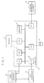
- Fig 1 is a block diagram of one type of system configuration that can implement the features of the present invention.
- Reference numeral 1 represents a display device that displays an output screen for a computer 4. Instructions for the computer 4 are entered from an input device 5 such as a keyboard and a pointing device, for example, a mouse.
- a video playback apparatus 10 is an optical disk or video cassette recorder (VCR). Video signals output from the video playback apparatus 10 are successively converted by an A/D converter 3 into digital image data, which is then supplied to the computer 4.
- the digital image data is entered through an interface 8 into a memory 9 and processed by a central processing unit (CPU) 7 according to a program stored in the memory 9.
- CPU central processing unit
- the video playback apparatus 10 When the frames of video handled by the video playback apparatus 10 are successively assigned with frame numbers, beginning with the head of the video, the video of a desired scene is replayed by sending the corresponding frame number to the video playback apparatus 10 through a control line 2.
- a variety of information may be stored in an external information storage 6, as required by the processing.
- the memory 9 stores various data generated by the processing described below and which is referenced as necessary.
- point of change detection processing which can prevent erroneous detection of an instantaneous image disturbance as a point of change during the process of detecting a point of change between video shots in a video.
- Fig. 2 is an example of a flowchart of a computer program for detecting a point of change between video shots in a video when the computer program is executed in the system shown in Fig. 1.
- the computer program is stored in the memory 9 and specifically is executed by the CPU 9.
- the CPU 7 takes in a frame image fn of the frame number n (step 202) and generates a color histogram Hn for the frame image fn (step 204).
- the color histogram determines the frequency that the pixel representing the same color appears in one whole frame image. For example, when a 64-color histogram with red (R), green (G) and blue (B) assigned with two bits each is to be generated, the RGB color values of individual pixels of the frame are reduced to 6-bit 64 colors represented by only higher-order two bits of R, G and B, and for each of the 64 colors the number of pixels representing the color after reduction is counted.
- the color histogram is represented by arrangement Hn(i) where i takes an integer from 0 to 63.
- the frequency Hn(0) when i is 0 represents how many pixels there are in the frame whose higher-order two bits of the RGB color values are zero for all R, G and B.
- the CPU 7 determines a difference R1n between the color histogram Hn and the color histogram Hn-1 of a frame fn-1 one frame before the current frame fn (step 206). Further, the CPU 7 calculates the difference R2n between Hn and the color histogram Hn-2 two frames before the current frame fn (step 208).
- the differences R1n and R2n between histograms can be determined from a calculation such as the x 2 test. Various kinds of calculations are described in the above-mentioned literature and hence a detailed explanation is omitted here.
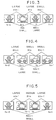
- Fig. 3 schematically illustrates a change with time of frame images when an instantaneous image disturbance occurs.
- a disturbance in frame fn-1 There is a disturbance in frame fn-1.
- the difference between frames fn-2 and fn-1 is large and R1n-1 exhibits a large value.
- the difference between frames fn-1 and fn is large and R1n shows a large value.
- frames fn-2 and fn are similar and R2n assumes a small value.
- Fig. 4 schematically illustrates a change with time in frame images including a change in video shots.
- the changes in video shots has occurred between frames fn-2 and fn-1.
- the difference between frames fn-2 and fn-1 is large and fn-1 exhibits a large value.
- Frames fn-1 and fn are similar and R1n assumes a small value.
- the difference between frames fn-2 and fn is large and R2n takes a large value.
- the conventional method focuses on only the value of R1n and thus cannot distinguish between the cases of Figs. 3 and 4, namely detecting the point between fn-2 and fn-1 as the point of change between video shots.
- R2n By using R2n in making the decision, it is possible to distinguish between Figs. 3 and 4. That is, if R1n-1 and R1n are both larger than a threshold th4 and R2n is smaller than a threshold th5, this is judged as an instantaneous disturbance (step 210). If R1n-1 is greater than a threshold thl, R1n is smaller than a threshold th2 and R2n is larger than a threshold th3, it is decided that there is a change in video shots between frames fn-2 and fn-1 (step 214), and the processing associated with the detection of the point of change between video shots is performed (step 216).
- the point of change between video shots may be located, i.e., the condition of (1) may be recognized as Fig. 3 and the condition of (2) as Fig. 4.
- the additional use of the R2n value makes the decision very reliable because it can confirm the return of the image to normal after disturbance. If the CPU 7 determines via step 210 the detected change to be an instantaneous disturbance, Rln-1 and R1n are reset to zero (step 212). If R1n-1 and R1n are not reset, a resulting combination in which R1n is large, R1n+1 is small and R2n+1 is large, as shown in Fig. 3, causes the CPU 7 via the step 214 in the next n+1st frame processing to detect the point between frames fn-1 and fn as a change in video shots.
- the above-described processing makes it possible to reliably detect a point of change between video shots even when there are instantaneous disturbances in video images.
- a part where instantaneous disturbance has occurred can also be located.
- the most typical case of instantaneous disturbance is when a camera strobe flashes as in a press conference. Because a strobe flashing occurs when a newsman thinks the scene is important, the part of the video where the flash occurs is often an important scene. Hence, this may be used as one of the means to pick up important scenes from the video.
- Another typical case of instantaneous disturbance is an intentional one used to have a psychological effect on viewers, such as illegal subliminal advertising on television.
- the above-described processing can also be used to automatically check if the video contains any such unlawful effects and thereby prevent broadcasting of such a video.
- the CPU 7 increments by one the frame number to be processed and prepares to take in the next frame (step 218).
- the computer program executed by the CPU 7 so as to perform the point of change detection method illustrated in Fig. 2, includes various code sections corresponding to the steps.
- the code sections are written in a computer programming language executable by the CPU 7.
- the code sections corresponding to the steps 200-214 and 218 can be written in a high speed, low level computer programming language such as C or assembly language.
- the code section corresponding to step 216 can be written in a low speed, high level computer programming language such as BASIC or some other interpretive language.
- a point of change detection processing which flexibly responds to changes in the characteristic of the object video to correctly detect a point of change between video shots, as by suppressing overly sensitive detection of a change in a bright scene and preventing a failure to detect a change in a dark scene.
- Fig. 6 illustrates an example flowchart of a computer program for detecting a point of change between video shots in a video when the computer program is executed in the system shown in Fig. 1.
- the basic flow of the computer program is similar to the previous flowchart of Fig. 2, except that the threshold for determining the point of change between video shots in a video is variable in Fig. 6 while that of Fig. 2 is fixed.
- the advantage of using a variable threshold is explained by referring to Fig. 7.
- Fig. 7 takes for example a video consisting of three shots in a row, namely a bright scene with active motions 708, a dark scene 1 710, and a dark scene 2 712 and shows a typical change with time of the correlation coefficient between frames.
- 702 and 704 represent the positions where the shot changes.
- the correlation coefficient In a scene with active motions, the image difference between succeeding frames is large. Hence, in the interval of 708 the correlation coefficient continues to have relatively large values. In the dark scene, on the other hand, colors making up the frame image fall into only a few kinds centering around black, so that the shapes of histograms are similar and the correlation coefficients in the interval of 710 and 712 assume small values. In these intervals, the correlation coefficient is relatively small even at the point of change in video shots for the above reason.
- the threshold for determining a change in video shots is fixed at a constant value as shown by a broken line of 706, if the threshold is set relatively high, the point of change such as 704 in a dark scene may fail to be detected and if on the contrary the threshold is set relatively low, a part of the correlation coefficients like 700 in the interval where there is an active movement may result in an overly sensitive response.
- the above-mentioned Japan Patent Laid-Open No. 111181/1992 proposes a method that calculates the rate of change between the immediately preceding correlation coefficient and the present correlation coefficient and, when the rate of change exceeds an allowable value, decides that the detected change represents the change in video shots.
- the value of the correlation coefficient represents the amount of change in an image per unit time and thus corresponds to the moving speed of the camera or an object in the video.
- the rate of change assumes a small value whether or not the scene has a motion, with only the value at the change of shot rising sharply. Hence, it is possible to use the same threshold for dark scenes and for scenes with active motions.
- the rate of change 714 of 700 with respect to the immediately preceding correlation coefficient may be equal to or larger than the rate of change 716 in a dark scene. It is therefore necessary to deal flexibly with changes in the characteristic in each scene of video and thereby change the threshold in response to the characteristic change.
- the CPU 7 when executing the computer program, sets the variable n representing the frame number of the current shot to be processed to an initial value to reset the memory area used in the histogram (step 600).
- the initial value for n is given a start frame number of the video interval to be processed.
- the CPU 7 when executing the computer program takes in a frame image fn of the frame number n (step 602) and generates a color histogram Hn for the frame image fn (step 604). This is followed by the CPU 7 determining the average brightness level Bn of the frame Fn (step 606).
- a detailed flowchart of the step 606 is illustrated in Fig. 8.
- a brightness level Bp(x, y) is determined for each pixel in the frame Fn, where (x, y) represents a two-dimensional plane coordinates of a pixel in the frame fn.
- Bp(x, y) represents a brightness of a pixel when frame fn is a monochromatic image and, when it is a color image, a luminance component of a color of the pixel.
- the value of the luminance component may be used as is, i.e., in the YUV color system, the value of Y is used.
- the maximum value of each RGB component is taken as the luminance value.
- R(x, y) represents a red component of a pixel located at a position (x, y); and similarly, G(x, y) represents a green component and B(x, y) represents a blue component.
- the value of the green component may be used approximately as the value of Bp(x, y).
- the value of Bp(x, y) determined in this way is added to Bn (step 804) to obtain the ultimate luminance Bn of the entire frame.
- the above processing may be performed simultaneously with the calculation of the color histogram of step 604 to eliminate the repetition of processing such as reading of value of each pixel and incrementing of variables x and y, thus speeding up the processing.
- the CPU 7 calculates the difference R1n between the histogram Hn-1 of immediately preceding frame and the histogram Hn of the current frame fn (step 608).
- the CPU 7 changes the threshold according to the feature of the immediately preceding video image (step 610).
- the threshold th6 is given a value that permits best processing for a video image with a standard level of brightness and a small motion.
- ⁇ is a weight value indicating by how much the threshold th6 is varied up or down for a change in brightness; and ⁇ is a weight value that determines by how much the threshold th6 is varied for a certain magnitude of motion. If there are other factors that require the threshold to be changed, any necessary number of factors are added to the equation.
- the number of frames to be processed for the immediately preceding video image is one of the important factors. There are 30 frames per second for the video image of NTSC system. Depending on the capability of the computer, the timing of taking in the next frame may pass while calculating the correlation coefficient between frames. In this case, if the video image is replayed at an ordinary speed, the frame-to-frame correlation coefficient to be calculated is of course the one with one frame skipped. That is, the number of frames to be processed may be 30 frames per second or several frames per second depending on the processing capability of the computer.
- the threshold th6 may be changed at the initial stage to eliminate the need for considering changing the th6 at the time of calculating the th7.
- the CPU 7 checks to see if the R1n is greater than the th7 calculated as described above (step 612). If it is, the system decides that there is a change in video shots between n-1th frame and nth frame, and performs the change detection processing (step 614). Finally, the CPU 7 increments by one the frame number to be processed and prepares for taking in the next frame (step 616).
- the computer program represented by the flowchart illustrated in Fig. 6 includes various code sections corresponding to the steps.
- the code sections are written in a computer programming language executable by the CPU 7.
- the code sections corresponding to steps 600 - 612 and 616 can be written in a high speed, low-level computer programming language such as C or assembly language.
- the code section corresponding to step 614 can be written in a low speed, high level computer programming language such as BASIC or some other interpretive language.
- the threshold value is changed according to the feature of only one frame immediately preceding frame fn, it is possible to change it based on the history of the feature of an arbitrary number of immediately preceding frames. For example, as a measure of intensity of motion, the average value and maximum value of the correlation coefficient for several preceding frames may be used in stead of R1n-1 in the equation of step 610.
- the threshold for R1n may also be changed based on the features of the frames fn+1, fn+2, ... immediately following the fn. With this method, when the R1n exceeds the threshold, it is decided retrospectively that there was a change in shot between fn-1 and fn.
- FIG. 9 illustrates a flowchart of a computer program embodying such a combination. The contents of processes making up the flowchart illustrated in Fig. 9 are already described above.
- the CPU 7 sets the variable n representing the frame number of the current shot to be processed to an initial value to reset the memory area used for histogram (step 900).
- the initial value for n is given a start frame number of the video interval to be processed.
- the CPU 7 takes in a frame image fn of the frame number n (step 902) and generates a color histogram Hn for the frame image fn (step 904).
- the CPU 7 calculates the average brightness Bn (step 906), followed by a determination of the difference R1n between the color histogram Hn and the color histogram Hn-1 of the immediately preceding frame fn-1 (step 908).
- calculation is performed to determine the difference R2n between Hn and the color histogram Hn-2 of the frame fn-2 two frames before (step 910).
- the CPU 7 calculates the threshold th8 according to the feature of the immediately preceding video image (step 912). When R1n-1 and R1n are both greater than the threshold th4 and R2n is smaller than the threshold th5, this is taken to mean that an instantaneous disturbance has occurred (step 914).
- step 918 when R1n-1 is greater than the threshold th8, R1n is smaller than the threshold th2, and R2n is greater than the threshold th3, it is decided that there is a change in video shots between frames fn-2 and fn-1 (step 918), and a variety of processes associated with the detection of change are performed (step 920).
- step 914 decides that the detected change is an instantaneous disturbance
- R1n-1 and R1n are reset to zero (step 916).
- the CPU 7 increments by one the frame number to be processed and prepares for taking in the next frame (step 922).
- the computer program represented by the flowchart illustrated in Fig. 9 includes various code sections corresponding to the steps of the flowchart. Particularly, the code sections corresponding to steps 900 - 918 and 922 can be written in a high speed, low level computing programming language such as C or assembly language. The code section corresponding to step 920 can be written in a low-speed, high level computer programming language such as BASIC or some other interpretive language.
- the correlation coefficient may be determined, as described in the literature cited above, by dividing the frame image into blocks, calculating the histogram for each divided block to determine the correlation coefficient for each block, and making an overall decision on the combination of these correlation coefficients to determine the correlation coefficient of the entire frame. This procedure produces an effect of increasing the difference in the correlation coefficient value between the point of change in video shots and other intervals.
- the user may wish to add and register a point of change by watching the video image being processed and specifying an appropriate location of change. Because of the limited response speed of humans, a significant length of time often passes from the moment the user has found an appropriate location of change and decided to register it until the user specification is conveyed to the computer. Because of this time delay, the specified location of change may intolerably deviate from the originally intended location of change. Hence, it might be convenient if apparatus is provided which registers a location of change by subtracting a preset time interval according to the response speed of the user from the originally specified location. Another apparatus may also be useful which, contrary to the above described apparatus, registers a location of change by adding a preset time interval to the original location.
- the video is divided into part intervals. If the division is made irrespective of voice, later editing of the video may become difficult. For example, if an interval is divided while a person in the video is talking, the talk will not make sense when only one divided part is seen. This poses a problem particularly in a video edit system that selects and rearranges individual shots divided by the detected points of change.
- the voice signal is also checked. If this part of video has voice, the registration of change is not made until the voice is ended, i.e., a silent part is reached, at which time the point of change is registered. Whether the part being checked has voice or not can be determined from sound volume.
- Fig. 10 shows a typical example of a voice signal.
- the abscissa represents time and the ordinate represents the amplitude of sound. Because the sound volume is the amplitude of sound, when the amplitude is smaller than a preset threshold, it can be treated as a silent part. There may be an instantaneous small amplitude even in a voiced part. To prevent erroneous decision, the sound amplitude is checked for a predetermined length of time to confirm that the small-amplitude state continues, before detecting the silent part. This procedure is applicable either to the case where the computer automatically detects a point of change or to a case where the user makes his own decision in detecting a point of change.
- search and edit can be done on the basis of the shots.
- the contents of each shot can be identified by a picture.
- the frame image at that instant is extracted as a representative image, whose size is changed to an appropriate one for search and edit applications and which is stored as a file in a storage such as disk so that it can be retrieved as required. Processing associated with such storing operation is performed, for example, in step 216 of Fig. 2.
- a representative image In addition to the still picture of the frame image, it is possible to use as a representative image a moving image of a specified length of time starting from the detected point of change. As a representative image for the shot, it is often appropriate to use a picture some time after the point of change rather than a picture just at the point of change. It is therefore suited to use as the representative picture an image that is a specified time offset from the point of change. If the point of change detection processings described in Figs. 2 and 9 are used, however, because only after several frames have passed from the point of change, can it be decided whether or not the detected change is really the point of change between shots, an attempt to extract a representative image when the decision is made will take in an image that is already a predetermined time offset from the point of change. In this case, if the user wants to pick up a frame image at the exact point of change between video shots, it may be convenient if several preceding frames are stored in a buffer. The buffer stores the latest frames and addition of one frame erases the oldest one in
- apparatus which stores the frame number and time code of the original video tape in connection with the representative image.
- Other necessary information includes the duration of a shot, and actual time and date when the shot was broadcast on television.
- the time and date can easily be determined by reading the clock built into the computer, and the duration of shot can be calculated real time as a difference between times or frame numbers of two adjacent points of change. This information is also stored in connection with the representative image when the latter is stored.
- Attribute information that the user added to each representative image as necessary is also related to the representative image when they are stored.
- the representative image and its associated information may be related with each other by assigning the associated information to a file of the same file name as the representative image but with a different extension.
- the representative image may be stored in a CUT00001.IMG, the associated time in a CUT00001.TIM, and the duration in a CUT00001.DUR. Because the video consists of a plurality of shots, however, this procedure results in the number of files becoming too large, making the management difficult. It is therefore possible to manage these information in a single file.
- Fig. 11 illustrates an example of a file structure for use in the present invention.
- 1100 is a header table which stores information related to the entire file, such as an identifier to discriminate against other file format and the total number of registered shots.
- a representative image storage address table 1102 successively stores the same number of offset values as the total number of shots, each offset value representing from which position in the file the data of the representative image of a shot is stored.
- 1104 is a time code table and 1106 an attribute information table. When other related information is stored, necessary tables are prepared. These tables are so arranged that address information stored at the same locations in these tables from the head of the tables are related to the same representative image and are correlated to each other.
- 1108 to 1118 are data areas to store respective kinds of information.
- Fig. 12 illustrates an example screen of a video edit system that can locate the start of each shot of a video or a movie.
- 1 is the display, 1232 a speaker producing voice and background music, 5 an indirect pointing device such as mouse or a joystick, 1234 a keyboard, and 1230 a direct pointing device such as a touch panel.
- a monitor window 1200 in the display 1 has an operation panel 1202 of the same type as a video tape recorder (VTR) and allows the user to freely replay a video.
- the video displayed on the monitor screen corresponds to text in a book, and the panel (button) operation corresponds to page turning.
- a lower right window 1208 displays a list of representative scenes for the shots, and a center right window 1212 shows a list of subjects that appear on the video. These lists are generally called indices.
- the list of scenes in the window 1208 is prepared by selecting typical frame images from a variety of scenes in the video through the point of change detection method, reducing the selected scenes in size and arranging them in chronological order as icons. These pictures may be considered as headings of scenes and correspond to the table of contents in a book.
- Each subject is one of the important constituent elements of a scene and in this respect, corresponds to a key word in a text.
- the list of subjects in the window 1212 corresponds to indices.
- the list of subjects consists of icons 1214 indicating what the subject is and a display duration graph (bar graph) 1216 on the right side of the icons.
- the duration display graph (bar graph) indicates the time during which the subject appears in the video, with the left end of the bar representing the start of the video and the right end representing the end of the video. Clicking on the bar displays the video of that time interval on the monitor screen.
- 1204 is a cursor that moves according to the movement of the pointing device such as mouse.
- a window 1206 is a general input-output window to display a variety of information related to the video.
- the present invention can be incorporated as a function of a video edit program into high-end systems for broadcasting stations, and into workstations and personal computers. Further, the present invention can be realized as one function of electronic devices such as VTR and TV and can also be developed into various equipment and systems that realize video on demand (VOD).
- VTR video recorder
- VOD video on demand
- the present invention due to the ability to distinguish between an instantaneous image disturbance and a point of change between video shots, it is possible to prevent erroneous detection of a part having disturbances as a point of change between video shots and also to pick up only the part with the disturbance.
- the threshold for detecting a point of change can be dynamically changed according to the features of the immediately preceding video frame, it is possible to make a precise detection of a point of change according to the features of the video image, thus preventing erroneous detections.
Landscapes
- Engineering & Computer Science (AREA)
- Multimedia (AREA)
- Theoretical Computer Science (AREA)
- Library & Information Science (AREA)
- General Physics & Mathematics (AREA)
- Physics & Mathematics (AREA)
- General Engineering & Computer Science (AREA)
- Databases & Information Systems (AREA)
- Data Mining & Analysis (AREA)
- Human Computer Interaction (AREA)
- Computer Vision & Pattern Recognition (AREA)
- Image Analysis (AREA)
- Television Signal Processing For Recording (AREA)
- Processing Or Creating Images (AREA)
- Information Retrieval, Db Structures And Fs Structures Therefor (AREA)
Claims (24)
- Procédé pour détecter un changement entre des prises vidéo dans une vidéo incluant une pluralité d'images complètes successives, comportant les étapes consistant à :caractérisé en ce qu'il consiste àentrer ladite vidéo sur un dispositif de traitement,obtenir une grandeur caractéristique de chaque image complète de la vidéo entrée,déterminer chaque n-ième premier coefficient de corrélation (R1n) qui est la différence entre la grandeur caractéristique de la n-ième image complète et celle de la (n - 1)-ième image complète qui précède immédiatement la n-ième image complète,déterminer chaque n-ième second coefficient de corrélation (R2n) qui est la différence entre la grandeur caractéristique de la n-ième image complète et celle d'une seconde image complète précédente qui précède la n-ième image complète à raison d'au moins deux images complètes, etdétecter un changement entre images complètes sur la base d'une comparaison de leurs grandeurs caractéristiques,
décider qu'il y a un changement entre la n-ième image complète et la (n - 2)-ième image complète lorsque le (n - 1)-ième premier coefficient de corrélation (R1n-1) et le n-ième second coefficient de corrélation (R2n) se situent au-dehors de plages admissibles prédéterminées et le n-ième premier coefficient de corrélation (R1n) se situe dans lesdites plages. - Procédé selon la revendication 1, dans lequel un changement entre des prises vidéo est distingué à partir d'une perturbation durant un nombre arbitraire d'images complètes lorsque le n-ième second coefficient de corrélation (R2n) s'avère être dans lesdites plages admissibles prédéterminées, en augmentant le nombre d'images complètes entre ladite n-ième image complète et ladite seconde image complète précédente.
- Procédé selon la revendication 1 ou 2, comportant en outre les étapes consistant à :extraire une image complète située au niveau du point de changement entre prises vidéo ou décalée à partir de celui-ci à raison d'un nombre prédéterminé d'images complètes,redimensionner l'image complète selon une taille préétablie, etmémoriser l'image complète redimensionnée dans un dispositif ou support de mémorisation.
- Procédé selon la revendication 3, comportant en outre l'étape consistant à mémoriser l'image complète redimensionnée en la rapportant à au moins l'un des quatre éléments d'informations associées suivants :une première information représentant la position du point de changement dans la vidéo,une deuxième information représentant l'instant au niveau duquel intervient le point de changement,une troisième information représentant la distance ou le temps entre le point de changement et le point de changement immédiatement précédent, etune quatrième information décrivant les attributs du point de changement ou d'une prise commençant avec le point de changement.
- Système pour détecter un point de changement entre des prises vidéo dans une vidéo constituée d'une pluralité d'images complètes successives, comportantcaractérisé en ce que ledit dispositif de traitement (4) comporte en outreun dispositif de reproduction vidéo (10) pour reproduire la vidéo d'une manière chronologique une image complète à la fois,un affichage (1) pour afficher ladite vidéo, etun dispositif de traitement (4) pour calculer une grandeur caractéristique de chaque image complète de la vidéo entrée et détecter un changement entre les images complètes sur la base d'une comparaison de leurs grandeurs caractéristiques, ledit dispositif de traitement comportantdes moyens pour déterminer chaque n-ième premier coefficient de corrélation (R1n) qui est la différence entre la grandeur caractéristique de la n-ième image complète et celle de la (n - 1)-ième image complète qui précède immédiatement la n-ième image complète, etdes moyens pour déterminer chaque n-ième second coefficient de corrélation (R2n) qui est la différence entre la grandeur caractéristique de la n-ième image complète et celle d'une seconde image complète précédente qui précède la n-ième image complète à raison d'au moins deux images complètes,
des moyens pour décider qu'un changement s'est produit entre la n-ième image complète et la (n - 2)-ième image complète lorsque le (n - 1)-ième premier coefficient de corrélation (R1n-1) et le n-ième second coefficient de corrélation (R2n) se situent au-dehors de plages admissibles prédéterminées et le n-ième premier coefficient de corrélation (R1n) se situe dans lesdites plages. - Système selon la revendication 5, dans lequel ledit dispositif de traitement (4) inclut des moyens pour distinguer un changement entre prises vidéo à partir d'une perturbation durant un nombre arbitraire d'images complètes lorsque le n-ième second coefficient de corrélation (R2n) s'avère se trouver dans lesdites plages admissibles prédéterminées, en augmentant le nombre d'images complètes entre ladite n-ième image complète et ladite seconde image complète précédente.
- Système selon la revendication 5 ou 6, comportant en outre :des moyens pour extraire une image complète située au niveau du point de changement dans une prise ou une image complète située au niveau d'une position décalée par rapport au point de changement à raison d'un décalage prédéterminé,des moyens pour redimensionner l'image complète selon une taille préétablie, etun support de mémorisation (9) pour mémoriser l'image complète redimensionnée.
- Système selon la revendication 7, comportant en outre des moyens pour mémoriser l'image complète redimensionnée dans ledit support de mémorisation (9) en la rapportant à au moins l'un des éléments d'informations associées suivants :une première information représentant la position du point de changement dans la vidéo,une deuxième information représentant l'instant au niveau duquel intervient le point de changement,une troisième information représentant la distance ou le temps entre le point de changement et le point de changement immédiatement précédent, etune quatrième information décrivant les attributs du point de changement ou d'une prise commençant avec le point de changement.
- Produit programme informatique destiné à être utilisé avec un ordinateur ayant un affichage, adapté pour détecter un changement entre des prises vidéo à partir d'une vidéo constituée d'une pluralité d'images complètes successives, comportant :une première section de codage entrant la vidéo d'une manière chronologique une image complète à la fois sur un dispositif de traitement (4),une deuxième section de codage calculant une grandeur caractéristique des données image de la vidéo pour chaque image complète,une troisième section de codage déterminant chaque n-ième premier coefficient de corrélation (R1n) qui est une différence entre la grandeur caractéristique de la n-ième image complète et celle de la (n - 1)-ième image complète qui précède immédiatement la n-ième image complète, et chaque n-ième second coefficient de corrélation (R2n) qui est la différence entre la grandeur caractéristique de la n-ième image complète et celle d'une seconde image complète précédente qui précède la n-ième image complète à raison d'au moins deux images complètes, etune quatrième section de codage détectant un changement entre images complètes sur la base d'une comparaison de leurs grandeurs caractéristiques, caractérisé en ce queladite quatrième section de codage décide qu'un changement est intervenu entre la n-ième image complète et la (n - 2)-ième image complète lorsque le (n - 1)-ième premier coefficient de corrélation (R1n-1) et le n-ième second coefficient de corrélation (R2n) se situent au-dehors de plages admissibles prédéterminées, et le n-ième premier coefficient de corrélation (R1n) se situe dans lesdites plages.
- Produit programme selon la revendication 9, dans lequel ladite quatrième section de codage distingue un changement entre prises vidéo à partir d'une perturbation durant un nombre arbitraire d'images complètes lorsque le n-ième second coefficient de corrélation (R2n) s'avère se situer dans lesdites plages admissibles prédéterminées, en augmentant le nombre d'images complètes entre ladite n-ième image complète et ladite seconde image complète précédente.
- Produit programme selon la revendication 9 ou 10, comportant en outre :une cinquième section de codage extrayant une image complète située au niveau du point de changement dans la prise ou décalée par rapport à celui-ci à raison d'un nombre prédéterminé d'images complètes,une sixième section de codage redimensionnant l'image complète selon une taille préétablie, etune septième section de codage mémorisant l'image complète redimensionnée sur un support de mémorisation.
- Produit programme informatique selon la revendication 11, comportant en outre une huitième section de codage mémorisant l'image complète redimensionnée dans un support de mémorisation en la rapportant à au moins l'un des éléments d'informations associées suivants :une première information représentant la position du point de changement dans la vidéo,une deuxième information représentant l'instant au niveau duquel intervient le point de changement,une troisième information représentant la distance ou le temps entre le point de changement et le point de changement immédiatement précédent, etune quatrième information décrivant les attributs du point de changement ou d'une prise commençant avec le point de changement.
- Procédé selon l'une quelconque des revendications 1 à 4, dans lequel, en indiquant si le n-ième premier coefficient de corrélation R1n et le n-ième second coefficient de corrélation R2n se situent à l'extérieur des plages admissibles prédéterminées, ces plages sont changées en fonction de la grandeur caractéristique d'une image complète immédiatement précédente ou suivante.
- Procédé selon l'une quelconque des revendications 1 à 4, dans lequel les images complètes vidéo et les informations qui leur sont associées sont gérées dans un unique fichier.
- Procédé selon l'une quelconque des revendications 1 à 4, dans lequel un tampon est utilisé pour mémoriser deux ou plus de deux des images complètes les plus récentes ou des images redimensionnées à tout instant de sorte que, lorsqu'un point de changement dans une image complète précédente, l'image complète contenant le point de changement est extraite du tampon.
- Procédé selon l'une quelconque des revendications 1 à 4, dans lequel ladite grandeur caractéristique estun histogramme de couleur, oula luminosité générale, ouun coefficient de corrélation entre l'image complète courante et l'image complète immédiatement précédente ou suivante, oule nombre d'images complètes à traiter par unité de temps pour l'image vidéo immédiatement précédente ou suivante.
- Système selon l'une quelconque des revendications 5 à 8, dans lequel, en indiquant si le n-ième premier coefficient de corrélation R1n et le n-ième second coefficient de corrélation R2n se situent à l'extérieur des plages admissibles prédéterminées, ces plages sont changées en fonction de la grandeur caractéristique d'une image complète immédiatement précédente ou immédiatement suivante.
- Système selon l'une quelconque des revendications 5 à 8, dans lequel les images complètes vidéo et les informations qui leur sont associées sont gérées dans un unique fichier.
- Système selon l'une quelconque des revendications 5 à 8, dans lequel un tampon est utilisé pour mémoriser deux ou plus de deux images complètes les plus récentes ou images complètes redimensionnées à tout instant de sorte que, lorsqu'un point de changement est détecté dans une image complète précédente, l'image complète contenant le point de changement est extraite du tampon.
- Système selon l'une quelconque des revendications 5 à 8, dans lequel ladite grandeur caractéristique estun histogramme de couleur, oula luminosité générale, ouun coefficient de corrélation entre l'image complète courante et l'image complète immédiatement précédente ou suivante, oule nombre d'images complètes à traiter par unité de temps pour l'image vidéo immédiatement précédente ou suivante.
- Produit programme informatique selon l'une quelconque des revendications 9 à 12, dans lequel, en indiquant si le n-ième premier coefficient de corrélation R1n et le n-ième second coefficient de corrélation R2n se situent au-dehors des plages admissibles prédéterminées, ces plages sont modifiées en fonction de la grandeur caractéristique d'une image immédiatement précédente ou immédiatement suivante.
- Produit programme informatique selon l'une quelconque des revendications 9 à 12, dans lequel les images complètes vidéo et les informations qui leur sont associées sont gérées dans un unique fichier.
- Produit programme informatique selon l'une quelconque des revendications 9 à 12, dans lequel un tampon est utilisé pour mémoriser deux ou plus de deux images complètes les plus récentes ou images complètes redimensionnées à tout instant de sorte que, lorsqu'un point de changement est détecté dans une image complète précédente, l'image complète contenant le point de changement est extraite du tampon.
- Produit programme informatique selon l'une quelconque des revendications 9 à 12, dans lequel ladite grandeur caractéristique estun histogramme de couleur, oula luminosité générale, ouun coefficient de corrélation entre l'image complète courante et l'image complète immédiatement précédente ou suivante, oule nombre d'images complètes à traiter par unité de temps pour l'image vidéo immédiatement précédente ou suivante.
Applications Claiming Priority (3)
| Application Number | Priority Date | Filing Date | Title |
|---|---|---|---|
| JP3202795 | 1995-02-21 | ||
| JP32027/95 | 1995-02-21 | ||
| JP03202795A JP3823333B2 (ja) | 1995-02-21 | 1995-02-21 | 動画像の変化点検出方法、動画像の変化点検出装置、動画像の変化点検出システム |
Publications (2)
| Publication Number | Publication Date |
|---|---|
| EP0729117A1 EP0729117A1 (fr) | 1996-08-28 |
| EP0729117B1 true EP0729117B1 (fr) | 2001-11-21 |
Family
ID=12347389
Family Applications (1)
| Application Number | Title | Priority Date | Filing Date |
|---|---|---|---|
| EP96102603A Expired - Lifetime EP0729117B1 (fr) | 1995-02-21 | 1996-02-21 | Méthode et arrangement pour la détection des positions de changement dans des images animées |
Country Status (4)
| Country | Link |
|---|---|
| US (2) | US6157744A (fr) |
| EP (1) | EP0729117B1 (fr) |
| JP (1) | JP3823333B2 (fr) |
| DE (1) | DE69617072T2 (fr) |
Cited By (4)
| Publication number | Priority date | Publication date | Assignee | Title |
|---|---|---|---|---|
| US7742108B2 (en) | 2000-06-28 | 2010-06-22 | Sheraizin Semion M | Method and system for real time motion picture segmentation and superposition |
| US7805019B2 (en) | 2005-02-22 | 2010-09-28 | Sheraizin Vitaly S | Enhancement of decompressed video |
| USRE42148E1 (en) | 2000-01-23 | 2011-02-15 | Semion Sheraizin | Method and apparatus for visual lossless image syntactic encoding |
| US7903902B2 (en) | 2004-07-26 | 2011-03-08 | Sheraizin Semion M | Adaptive image improvement |
Families Citing this family (72)
| Publication number | Priority date | Publication date | Assignee | Title |
|---|---|---|---|---|
| JP3534368B2 (ja) * | 1996-04-03 | 2004-06-07 | 株式会社東芝 | 動画像処理方法及び動画像処理装置 |
| DE69732089T2 (de) * | 1996-10-04 | 2005-12-08 | Nippon Telegraph And Telephone Corp. | Vorrichtung und verfahren zur zeitlichen und räumlichen integration und verwaltung einer vielzahl von videos sowie speichermedium zur speicherung eines programms dafür |
| JP3780623B2 (ja) | 1997-05-16 | 2006-05-31 | 株式会社日立製作所 | 動画像の記述方法 |
| US6483540B1 (en) * | 1997-06-16 | 2002-11-19 | Casio Computer Co., Ltd. | Image data processing apparatus method and program storage medium for processing image data |
| JPH1132294A (ja) * | 1997-07-09 | 1999-02-02 | Sony Corp | 情報検索装置および方法、並びに伝送媒体 |
| JP3409834B2 (ja) * | 1997-07-10 | 2003-05-26 | ソニー株式会社 | 画像処理装置および画像処理方法、並びに記録媒体 |
| JPH1169372A (ja) * | 1997-08-14 | 1999-03-09 | Fuji Photo Film Co Ltd | 画像の明度調整方法およびその方法に使用するデジタルカメラ並びに画像処理装置 |
| EP2387038A3 (fr) * | 1997-10-17 | 2012-01-11 | Sony Corporation | Appareil et procédé de traitement pour l'enregistrement, appareil et procédé de traitement pour la reproduction, programme pour contrôler un appareil d'enregistrement, programme pour contrôler un appareil de reproduction, support d'enregistrement |
| JPH11146325A (ja) * | 1997-11-10 | 1999-05-28 | Hitachi Ltd | 映像検索方法および装置並びに映像情報作成方法およびその処理プログラムを格納した記憶媒体 |
| US5990980A (en) * | 1997-12-23 | 1999-11-23 | Sarnoff Corporation | Detection of transitions in video sequences |
| KR100264798B1 (ko) * | 1997-12-31 | 2000-09-01 | 윤종용 | 직접 액세스 재생을 위한 광 디스크 기록장치와 직접액세스 재생방법 |
| JP3738939B2 (ja) * | 1998-03-05 | 2006-01-25 | Kddi株式会社 | 動画像のカット点検出装置 |
| JP3098736B2 (ja) * | 1998-04-15 | 2000-10-16 | 日本放送協会 | 映像再生制御装置および記憶媒体 |
| US6370315B1 (en) * | 1998-04-30 | 2002-04-09 | Matsushita Electric Industrial Co., Ltd. | Playback time compression and expansion method and apparatus |
| JP3622527B2 (ja) * | 1998-08-24 | 2005-02-23 | 株式会社日立製作所 | 映像の特徴場面検出方法及び装置 |
| JP3453312B2 (ja) * | 1998-09-03 | 2003-10-06 | 株式会社リコー | 映像ストリームの構造解析過程表示方法 |
| GB9825379D0 (en) * | 1998-11-19 | 1999-01-13 | Electrosonic Ltd | Image processing |
| DE19859087A1 (de) | 1998-12-10 | 2000-06-15 | Arnold & Richter Kg | Verfahren zur Trennung von auf Medien wie Laufbildfilmen, Videobändern o. dgl. gespeicherten Bildfolgen in Einzelsequenzen |
| JP3569800B2 (ja) * | 1998-12-24 | 2004-09-29 | カシオ計算機株式会社 | 画像処理装置及び画像処理方法 |
| JP2000276469A (ja) * | 1999-03-23 | 2000-10-06 | Canon Inc | 情報検索装置及びその方法、記憶媒体 |
| US6542619B1 (en) * | 1999-04-13 | 2003-04-01 | At&T Corp. | Method for analyzing video |
| JP2000350156A (ja) | 1999-06-09 | 2000-12-15 | Hitachi Ltd | 動画像情報の記憶方法及びこれを記録した記録媒体 |
| KR100608454B1 (ko) * | 1999-10-19 | 2006-08-02 | 삼성전자주식회사 | 키프레임을 이용한 동화상 기록 및/또는 재생장치 |
| US6801294B2 (en) * | 1999-10-19 | 2004-10-05 | Samsung Electronics Co., Ltd. | Recording and/or reproducing apparatus and method using key frame |
| US7016540B1 (en) * | 1999-11-24 | 2006-03-21 | Nec Corporation | Method and system for segmentation, classification, and summarization of video images |
| JP4803544B2 (ja) * | 2000-04-05 | 2011-10-26 | ソニー ヨーロッパ リミテッド | オーディオ/ビデオ再生装置及び方法 |
| JP4683253B2 (ja) * | 2000-07-14 | 2011-05-18 | ソニー株式会社 | Av信号処理装置および方法、プログラム、並びに記録媒体 |
| US6834080B1 (en) * | 2000-09-05 | 2004-12-21 | Kabushiki Kaisha Toshiba | Video encoding method and video encoding apparatus |
| US7038736B2 (en) | 2000-09-21 | 2006-05-02 | Canon Kabushiki Kaisha | Moving image processing apparatus and method, and computer readable memory |
| DE10050083A1 (de) * | 2000-10-10 | 2002-04-18 | Sick Ag | Vorrichtung und Verfahren zur Erfassung von Objekten |
| US6714594B2 (en) * | 2001-05-14 | 2004-03-30 | Koninklijke Philips Electronics N.V. | Video content detection method and system leveraging data-compression constructs |
| JP3840928B2 (ja) * | 2001-07-17 | 2006-11-01 | ソニー株式会社 | 信号処理装置および方法、記録媒体、並びにプログラム |
| US7013803B2 (en) | 2002-02-06 | 2006-03-21 | Quad/Tech, Inc. | Color registration control system for a printing press |
| US7253929B2 (en) * | 2002-02-06 | 2007-08-07 | Quad/Tech, Inc. | Camera assembly for a printing press |
| JP4211023B2 (ja) * | 2002-02-22 | 2009-01-21 | 富士通株式会社 | 動画像処理方法及び動画像処理装置 |
| US7251413B2 (en) | 2002-04-26 | 2007-07-31 | Digital Networks North America, Inc. | System and method for improved blackfield detection |
| US20040131117A1 (en) * | 2003-01-07 | 2004-07-08 | Sheraizin Vitaly S. | Method and apparatus for improving MPEG picture compression |
| GB2398690B (en) * | 2003-02-21 | 2006-05-10 | Sony Comp Entertainment Europe | Control of data processing |
| JP4026071B2 (ja) * | 2003-09-25 | 2007-12-26 | ソニー株式会社 | 車載装置及びコンテンツ提供方法 |
| KR100597398B1 (ko) * | 2004-01-15 | 2006-07-06 | 삼성전자주식회사 | 비디오 클립을 검색하는 장치 및 방법 |
| US20050248576A1 (en) * | 2004-05-07 | 2005-11-10 | Sheng-Hung Chen | Transformation method and system of computer system for transforming a series of video signals |
| TWI242376B (en) * | 2004-06-24 | 2005-10-21 | Via Tech Inc | Method and related system for detecting advertising by integrating results based on different detecting rules |
| TWI245568B (en) * | 2004-07-22 | 2005-12-11 | Via Tech Inc | Method and related system for high efficient advertising detection |
| JP4660736B2 (ja) * | 2004-09-24 | 2011-03-30 | 独立行政法人産業技術総合研究所 | 動画像時間分割処理方法および装置 |
| JP4243862B2 (ja) * | 2004-10-26 | 2009-03-25 | ソニー株式会社 | コンテンツ利用装置およびコンテンツ利用方法 |
| US7613383B2 (en) | 2004-12-02 | 2009-11-03 | Hitachi, Ltd. | Editing method and recording and reproducing device |
| JP4595555B2 (ja) * | 2005-01-20 | 2010-12-08 | ソニー株式会社 | コンテンツ再生装置およびコンテンツ再生方法 |
| JP4247626B2 (ja) * | 2005-01-20 | 2009-04-02 | ソニー株式会社 | 再生装置および再生方法 |
| JP4741267B2 (ja) * | 2005-03-28 | 2011-08-03 | ソニー株式会社 | コンテンツ推薦システム、通信端末およびコンテンツ推薦方法 |
| JP4515332B2 (ja) * | 2005-05-30 | 2010-07-28 | オリンパス株式会社 | 画像処理装置及び対象領域追跡プログラム |
| JP2007011928A (ja) * | 2005-07-04 | 2007-01-18 | Sony Corp | コンテンツ提供システム、コンテンツ提供装置、コンテンツ配信サーバ、コンテンツ受信端末およびコンテンツ提供方法 |
| JP5133508B2 (ja) | 2005-07-21 | 2013-01-30 | ソニー株式会社 | コンテンツ提供システム、コンテンツ提供装置、コンテンツ配信サーバ、コンテンツ受信端末およびコンテンツ提供方法 |
| GB2430102A (en) * | 2005-09-09 | 2007-03-14 | Snell & Wilcox Ltd | Picture loss detection by comparison of plural correlation measures |
| US7555149B2 (en) * | 2005-10-25 | 2009-06-30 | Mitsubishi Electric Research Laboratories, Inc. | Method and system for segmenting videos using face detection |
| WO2007049378A1 (fr) * | 2005-10-25 | 2007-05-03 | Mitsubishi Electric Corporation | Dispositif d'identification video |
| JP4811046B2 (ja) | 2006-02-17 | 2011-11-09 | ソニー株式会社 | コンテンツの再生装置、オーディオ再生機およびコンテンツの再生方法 |
| US8218903B2 (en) * | 2007-04-24 | 2012-07-10 | Sony Computer Entertainment Inc. | 3D object scanning using video camera and TV monitor |
| WO2008152556A1 (fr) * | 2007-06-15 | 2008-12-18 | Koninklijke Philips Electronics N.V. | Procédé et appareil pour générer automatiquement des résumés d'un fichier multimédia |
| US8320717B2 (en) * | 2008-03-31 | 2012-11-27 | Brother Kogyo Kabushiki Kaisha | Image processor |
| US8717435B2 (en) * | 2008-04-09 | 2014-05-06 | Hbc Solutions, Inc. | Video monitoring device providing parametric signal curve display features and related methods |
| JP5295638B2 (ja) * | 2008-05-22 | 2013-09-18 | 池上通信機株式会社 | テレビカメラ |
| JP5111269B2 (ja) * | 2008-07-09 | 2013-01-09 | キヤノン株式会社 | 画像処理装置、画像処理方法 |
| KR101001543B1 (ko) * | 2008-08-04 | 2010-12-17 | 삼성전자주식회사 | 온 스크린 디스플레이의 표시 시간 조절 장치 및 방법 |
| JP5071988B2 (ja) * | 2009-04-24 | 2012-11-14 | Kddi株式会社 | 動画像のカット点検出装置 |
| JP5561524B2 (ja) * | 2010-03-19 | 2014-07-30 | ソニー株式会社 | 画像処理装置および方法、並びにプログラム |
| US8786785B2 (en) * | 2011-04-05 | 2014-07-22 | Microsoft Corporation | Video signature |
| US8897553B2 (en) | 2011-12-13 | 2014-11-25 | The Nielsen Company (Us), Llc | Image comparison using color histograms |
| US8750613B2 (en) | 2011-12-13 | 2014-06-10 | The Nielsen Company (Us), Llc | Detecting objects in images using color histograms |
| US8897554B2 (en) | 2011-12-13 | 2014-11-25 | The Nielsen Company (Us), Llc | Video comparison using color histograms |
| US8761448B1 (en) | 2012-12-13 | 2014-06-24 | Intel Corporation | Gesture pre-processing of video stream using a markered region |
| CN108830885B (zh) * | 2018-05-31 | 2021-12-07 | 北京空间飞行器总体设计部 | 一种基于多向差分残差能量相关的检测虚警抑制方法 |
| CN111726569A (zh) * | 2019-12-10 | 2020-09-29 | 李军 | 监控内容替换检测系统及方法 |
Family Cites Families (11)
| Publication number | Priority date | Publication date | Assignee | Title |
|---|---|---|---|---|
| US4998287A (en) * | 1988-10-14 | 1991-03-05 | General Instrument Corporation | Determination of sequential positions of video fields derived from film |
| JP2643422B2 (ja) * | 1989-03-14 | 1997-08-20 | 松下電器産業株式会社 | 相関演算装置 |
| GB9001468D0 (en) * | 1990-01-23 | 1990-03-21 | Sarnoff David Res Center | Computing multiple motions within an image region |
| US5099322A (en) * | 1990-02-27 | 1992-03-24 | Texas Instruments Incorporated | Scene change detection system and method |
| US5091782A (en) * | 1990-04-09 | 1992-02-25 | General Instrument Corporation | Apparatus and method for adaptively compressing successive blocks of digital video |
| JP2863818B2 (ja) * | 1990-08-31 | 1999-03-03 | 工業技術院長 | 動画像の変化点検出方法 |
| DE69322470T2 (de) * | 1992-08-12 | 1999-07-15 | International Business Machines Corp., Armonk, N.Y. | System und Verfahren zur Lokalisierung von Videosegmentübergängen |
| KR0184313B1 (ko) | 1993-04-09 | 1999-05-01 | 모리시타 요이찌 | 디지털영상신호를 스크램블 및 디스크램블해서 전송하는 스크램블전송장치 |
| CA2114052A1 (fr) * | 1993-07-29 | 1995-01-30 | Monica Medina-Puri | Methode pour detecter les scenes coupees |
| US5642294A (en) * | 1993-12-17 | 1997-06-24 | Nippon Telegraph And Telephone Corporation | Method and apparatus for video cut detection |
| US5635982A (en) * | 1994-06-27 | 1997-06-03 | Zhang; Hong J. | System for automatic video segmentation and key frame extraction for video sequences having both sharp and gradual transitions |
-
1995
- 1995-02-21 JP JP03202795A patent/JP3823333B2/ja not_active Expired - Lifetime
-
1996
- 1996-02-21 DE DE69617072T patent/DE69617072T2/de not_active Expired - Lifetime
- 1996-02-21 US US08/604,606 patent/US6157744A/en not_active Expired - Lifetime
- 1996-02-21 EP EP96102603A patent/EP0729117B1/fr not_active Expired - Lifetime
-
2000
- 2000-07-26 US US09/626,115 patent/US6256419B1/en not_active Expired - Lifetime
Non-Patent Citations (1)
| Title |
|---|
| HONGJIANG ZHANG, ATREYI KANKANHALLI, SMOLIAR S. W.: "AUTOMATIC PARTITIONING OF FULL-MOTION VIDEO.", MULTIMEDIA SYSTEMS., ACM, NEW YORK, NY., US, vol. 01., no. 01., 1 January 1993 (1993-01-01), US, pages 10 - 28., XP000572496, ISSN: 0942-4962, DOI: 10.1007/BF01210504 * |
Cited By (5)
| Publication number | Priority date | Publication date | Assignee | Title |
|---|---|---|---|---|
| USRE42148E1 (en) | 2000-01-23 | 2011-02-15 | Semion Sheraizin | Method and apparatus for visual lossless image syntactic encoding |
| US7742108B2 (en) | 2000-06-28 | 2010-06-22 | Sheraizin Semion M | Method and system for real time motion picture segmentation and superposition |
| US8098332B2 (en) | 2000-06-28 | 2012-01-17 | Somle Development, L.L.C. | Real time motion picture segmentation and superposition |
| US7903902B2 (en) | 2004-07-26 | 2011-03-08 | Sheraizin Semion M | Adaptive image improvement |
| US7805019B2 (en) | 2005-02-22 | 2010-09-28 | Sheraizin Vitaly S | Enhancement of decompressed video |
Also Published As
| Publication number | Publication date |
|---|---|
| EP0729117A1 (fr) | 1996-08-28 |
| JPH08227462A (ja) | 1996-09-03 |
| US6157744A (en) | 2000-12-05 |
| DE69617072D1 (de) | 2002-01-03 |
| JP3823333B2 (ja) | 2006-09-20 |
| US6256419B1 (en) | 2001-07-03 |
| DE69617072T2 (de) | 2002-08-29 |
Similar Documents
| Publication | Publication Date | Title |
|---|---|---|
| EP0729117B1 (fr) | Méthode et arrangement pour la détection des positions de changement dans des images animées | |
| JP2994177B2 (ja) | ビデオ・セグメント間の境界部の位置を特定するためのシステム及び方法 | |
| JP4981128B2 (ja) | 映像からのキーフレーム抽出 | |
| JP3250467B2 (ja) | 映像要約方法および映像表示方法 | |
| US6014183A (en) | Method and apparatus for detecting scene changes in a digital video stream | |
| JP3361587B2 (ja) | 動画像検索装置及び方法 | |
| US20070074115A1 (en) | Automatic capturing and editing of a video | |
| JPH09130732A (ja) | シーンチェンジ検出方法および動画像編集装置 | |
| US6341168B1 (en) | Method and apparatus for detecting and displaying a representative image of a shot of short duration in a moving image | |
| US6434320B1 (en) | Method of searching recorded digital video for areas of activity | |
| JPH0993588A (ja) | 動画像処理方法 | |
| JP2000350156A (ja) | 動画像情報の記憶方法及びこれを記録した記録媒体 | |
| JP3728775B2 (ja) | 動画像の特徴場面検出方法及び装置 | |
| JP3240871B2 (ja) | 映像要約方法 | |
| JP3258924B2 (ja) | シーン管理装置、シーン管理方法及び記録媒体 | |
| JP4154012B2 (ja) | 画像表示方法を実現するためのプログラムを記録した記録媒体及び画像合成装置 | |
| US20070061727A1 (en) | Adaptive key frame extraction from video data | |
| JP2007149095A (ja) | 動画像の変化点検出方法及び装置 | |
| US7440595B2 (en) | Method and apparatus for processing images | |
| JP2001119661A (ja) | 動画編集システムおよび記録媒体 | |
| JPH11261946A (ja) | 映像表示方法および装置並びに該映像表示方法を記録した記録媒体 | |
| JP3157928B2 (ja) | 動画像の拾い見装置 | |
| JP3379453B2 (ja) | 字幕領域検出方法及びその装置、並びに動画像検索方法及びその装置 | |
| JP3941808B2 (ja) | 動画像の変化点検出方法及び装置 | |
| JP3067043B2 (ja) | 動画のカット自動分割方法 |
Legal Events
| Date | Code | Title | Description |
|---|---|---|---|
| PUAI | Public reference made under article 153(3) epc to a published international application that has entered the european phase |
Free format text: ORIGINAL CODE: 0009012 |
|
| AK | Designated contracting states |
Kind code of ref document: A1 Designated state(s): DE FR GB |
|
| 17P | Request for examination filed |
Effective date: 19970218 |
|
| 17Q | First examination report despatched |
Effective date: 20000217 |
|
| GRAG | Despatch of communication of intention to grant |
Free format text: ORIGINAL CODE: EPIDOS AGRA |
|
| GRAG | Despatch of communication of intention to grant |
Free format text: ORIGINAL CODE: EPIDOS AGRA |
|
| GRAG | Despatch of communication of intention to grant |
Free format text: ORIGINAL CODE: EPIDOS AGRA |
|
| GRAH | Despatch of communication of intention to grant a patent |
Free format text: ORIGINAL CODE: EPIDOS IGRA |
|
| GRAH | Despatch of communication of intention to grant a patent |
Free format text: ORIGINAL CODE: EPIDOS IGRA |
|
| GRAA | (expected) grant |
Free format text: ORIGINAL CODE: 0009210 |
|
| AK | Designated contracting states |
Kind code of ref document: B1 Designated state(s): DE FR GB |
|
| REG | Reference to a national code |
Ref country code: GB Ref legal event code: IF02 |
|
| REF | Corresponds to: |
Ref document number: 69617072 Country of ref document: DE Date of ref document: 20020103 |
|
| PLBE | No opposition filed within time limit |
Free format text: ORIGINAL CODE: 0009261 |
|
| STAA | Information on the status of an ep patent application or granted ep patent |
Free format text: STATUS: NO OPPOSITION FILED WITHIN TIME LIMIT |
|
| 26N | No opposition filed | ||
| REG | Reference to a national code |
Ref country code: FR Ref legal event code: PLFP Year of fee payment: 20 |
|
| PGFP | Annual fee paid to national office [announced via postgrant information from national office to epo] |
Ref country code: DE Payment date: 20150218 Year of fee payment: 20 |
|
| PGFP | Annual fee paid to national office [announced via postgrant information from national office to epo] |
Ref country code: GB Payment date: 20150218 Year of fee payment: 20 Ref country code: FR Payment date: 20150210 Year of fee payment: 20 |
|
| REG | Reference to a national code |
Ref country code: DE Ref legal event code: R071 Ref document number: 69617072 Country of ref document: DE |
|
| REG | Reference to a national code |
Ref country code: GB Ref legal event code: PE20 Expiry date: 20160220 |
|
| PG25 | Lapsed in a contracting state [announced via postgrant information from national office to epo] |
Ref country code: GB Free format text: LAPSE BECAUSE OF EXPIRATION OF PROTECTION Effective date: 20160220 |