EP0729109B1 - Lecteur de carte à puce - Google Patents
Lecteur de carte à puce Download PDFInfo
- Publication number
- EP0729109B1 EP0729109B1 EP95119824A EP95119824A EP0729109B1 EP 0729109 B1 EP0729109 B1 EP 0729109B1 EP 95119824 A EP95119824 A EP 95119824A EP 95119824 A EP95119824 A EP 95119824A EP 0729109 B1 EP0729109 B1 EP 0729109B1
- Authority
- EP
- European Patent Office
- Prior art keywords
- chip card
- contact carrier
- contacts
- separating element
- housing
- Prior art date
- Legal status (The legal status is an assumption and is not a legal conclusion. Google has not performed a legal analysis and makes no representation as to the accuracy of the status listed.)
- Expired - Lifetime
Links
Images
Classifications
-
- G—PHYSICS
- G06—COMPUTING; CALCULATING OR COUNTING
- G06K—GRAPHICAL DATA READING; PRESENTATION OF DATA; RECORD CARRIERS; HANDLING RECORD CARRIERS
- G06K7/00—Methods or arrangements for sensing record carriers, e.g. for reading patterns
- G06K7/0013—Methods or arrangements for sensing record carriers, e.g. for reading patterns by galvanic contacts, e.g. card connectors for ISO-7816 compliant smart cards or memory cards, e.g. SD card readers
- G06K7/0021—Methods or arrangements for sensing record carriers, e.g. for reading patterns by galvanic contacts, e.g. card connectors for ISO-7816 compliant smart cards or memory cards, e.g. SD card readers for reading/sensing record carriers having surface contacts
Definitions
- the invention relates to a chip card reader with a Housing, a guideway formed in the housing for Inclusion of a chip card and a housing side Contact carrier, whose contacts with corresponding Contacts of the chip card in the reading point of the chip card in the Housing can be contacted.
- Smart card readers are responsible for the contacts on the associated card arranged electronic chips in one certain end position (reading position) of the card in the reader contact so as to "read" the information of the chip, but possibly also entering information in to enable the chip card.
- Smart card readers of the type mentioned are diverse today Application, for example in so-called stationary Card phones, but also in cell phones, ATMs or similar.
- a chip card reader of the type mentioned is in the DE 38 10 275 A1 described.
- This chip card reader has a mobile contact carrier in the Frame of the reader who parallel to the introduction of the Chip card is guided against the card for contacting.
- the electronic connection of the contacts of the chip with the Contact of the contact carrier is via a limit switch reached after reaching the end position of the Chip card in the reader (reading position) by running onto the Frame (the housing) is operated.
- the invention is therefore based on the object Offer smart card reader of the generic type, the additional security features regarding a has unauthorized mechanical intervention.
- the invention is based on the finding that achieved this goal in a surprisingly simple way can be that the contacts of the contact carrier in a Starting position of the reader opposite by a separating element the guideway for the chip card are sealed off.
- the smart card reader to design that the "protective position" of the separating element relative to the contact carrier when properly inserted a chip card is appropriately revoked in order to then, in the reading position of the chip card, the contacts of the Chip card and the contact carrier securely together to contact.
- the additional inventive idea can be generally formulate that when the Chip card or at the latest when reaching the End position of the chip card, the separating element or the Contact carriers are shifted so far relative to each other, that the contacts of the contact carrier the contacts of the Chip card opposite, so without intermediate Separating element. It is also an additional measure ensure that the separation element "raised position" of the contact carrier in relation to the Chip card at the latest in the end position of the chip card is canceled and the contacts of the chip card securely against the contacts of the contact carrier are in contact.
- the invention proposes a total of four Embodiments, all of which are the same The underlying idea of the invention.
- the contact carrier is like this designed that he relative to the insertion of the chip card Separating element away from this and the contact carrier or its contacts against the contacts of Chip card are movable.
- the separating element is accordingly stationary.
- the reader is in the starting position the contact carrier "behind” the separating element (based on the Guideway) and only when the chip card is inserted the contact carrier of this protective separating element moved sideways and then against the chip card guided.
- the contact carrier is like this designed that he relative to the insertion of the chip card Separating element is moved away from this and the chip card or their contacts on their way to the Reading position of the chip card along the guideway against the contacts of the contact carrier are movable.
- the relative movement of the contact carrier corresponds here and separator of that of the first embodiment. in the Contrary to the first embodiment, however, the Chip card moved towards the contact carrier to the ensure the desired contact. Appropriate Guides along the guideway serve to move the Chip card against the contact carrier.
- the third embodiment has the following features marked:
- the separating element is when inserting the Chip card in the guideway relative to the contact carrier of this movable away and the contact carrier respectively the contacts of which are further on in the chip card the reading position against the contacts of the chip card.
- the fourth embodiment differs from that third embodiment in that the chip card - after Detach the contact carrier from the separating element - against the Contact carrier or its contacts performed ("raised”). Otherwise it also applies here that the constructive design is such that the separating element relative to the insertion of the chip card into the guideway to the contact carrier and away from it is "exposed”.
- the design of a chip card reader according to the invention provides safe protection against simple means Vandalism is available, with the other features of a Chip card reader unchanged from the prior art can remain, for example means to hold the Card in the reading position or contacting the Contacts via a limit switch.
- the plate mentioned is preferably in Bottom of the guideway and flush with it.
- the chip card can be inserted into the Guide path are introduced and effects after reaching a stop described in more detail below Carriage of the carriage and parallel to the separation of the Contact carrier from the separating element and the lowering of the Contact carrier along a corresponding "skew Level "until the final contact position on the Contacts of the chip card.
- this can be done using appropriate clamping devices or hook between chip card and contact carrier (slide) respectively.
- the tension for example with A tension spring can be provided and the tension spring with one end on the contact carrier (slide) and can be attached to the housing with the other end.
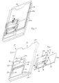
- the housing 10 of Figure 1 has essentially one outer cuboid shape and is at one end 10.1 "open” and with an insertion opening 12 for a chip card 14 formed, with the insertion opening 12 in Direction to the other end 10.2 of the housing 10 one Guideway 16 for essentially play-free inclusion of Chip card 14 connects.
- the width is accordingly Guideway 16 equal to or slightly larger than that Width of the chip card 14 and the height of the guideway 16 equal or slightly larger than the thickness of the chip card 14.
- the housing 10 is open at the top (Opening 20) and a frame 18 is circumferentially over the Cover 10d of the housing 10 in front and is towards the Extended end 10.1, this frame part 18.1 a has a greater height than the frame part 18.2 in the area the opening 20.
- Frame section 18.1.1 is perforated in the middle and behind the opening 22 is a bearing hook 24a on the Housing cover 10d arranged.
- the frame section 18.1 encompasses one of the openings 20 adjacent cover part 26, hereinafter referred to as Separating element is called.
- the separating element is from the The frame wall 18.1.1 is inclined towards the opening 20.
- Figure 2 shows a carriage
- the total Reference number 30 bears and consists of a plate 32 which, as Figure 3 shows, in a corresponding recess of the housing base 10b runs and laterally angled edges 32k safely in the longitudinal direction of the housing (between the ends 10.1 and 10.2) is slidable.
- the plate 32 extends in the region of the opening 20 Journal 34 vertically upwards, on which arms 36 rotatable are articulated, a contact carrier 38 between them record, which has contacts 40 on the underside. Below of the contact carrier 38 is the plate 32 with a corresponding recess 42 is formed.
- Figure 3 shows the housing 10 and the carriage 30 according to the Figures 1 and 2 in the assembled (assembled) Status. Thereafter, the journals 34 and 34 extend Arms 36 and the contact carrier 38 through the opening 20 over the separating element 26, the contact carrier 38 via the lateral arms 36 guided in the grooves 28 of the frame 18 becomes.
- a hook 24b in the area of the front face of the Contact carrier 38 serves to receive a tension spring 46, the other end of the hook 24a on the housing cover 10d is attached.
- the carriage 30 in the held in the position shown in Figure 3, where a Guided by the arms 36 in the grooves 28 and over the angled edges 32k of the plate 32 in the guideway 16 results.
- the front end of the chip card 14 strikes one Stop 48 and causes the carriage 30 against the force of the tension spring 46 towards the housing end 10.2 is moved forward.
- Contact carrier 38 along the grooves 28 also in the direction led to the housing end 10.2 and relative to Separating element 26 moves and released from this. Due to the the contact carrier 38 becomes inclined simultaneously down towards the chip card 14, lowered, to the extent that in the (not here shown) end position of the chip card 14, the contacts 40 of the contact carrier 38 corresponding contacts on the Contact chip card 14, simultaneously via one (Also not shown here) limit switches electronic connection between the mutual Contacts is triggered.
Claims (5)
- Lecteur de carte à puce comprenant un boítier (10), une glissière de guidage (16) réalisée dans le boítier (10) et destinée à recevoir une carte à puce (14), ainsi qu'un porte-contacts (38) sur le côté du boítier, dont les contacts (40) peuvent entrer en contact avec les contacts correspondants de la carte à puce (14) dans la position de lecture de la carte (14) dans le boítier (10), caractérisé en ce que
les contacts (40) du porte-contacts (38), dans une position initiale du lecteur, sont protégés face à la glissière de guidage (16) par un élément de séparation (26), etau moment de l'insertion de la carte à puce (14), le porte-contacts (38) s'écarte de l'élément de séparation (26) et, pendant le déplacement de la carte à puce (14) vers la position de lecture, le porte-contacts (38), plus précisément ses contacts (40), se déplace contre les contacts de la carte à puce, ouau moment de l'insertion de la carte à puce, le porte-contacts s'écarte de l'élément de séparation et, pendant le déplacement de la carte à puce vers la position de lecture, la carte à puce, plus précisément ses contacts, se déplace le long de la glissière de guidage contre les contacts du porte-contacts, ouau moment de l'insertion de la carte à puce dans la glissière de guidage, l'élément de séparation s'écarte du porte-contacts et, pendant le déplacement de la carte à puce vers la position de lecture, le porte-contacts, plus précisément ses contacts, se déplace contre les contacts de la carte à puce, ouau moment de l'insertion de la carte à puce dans la glissière de guidage, l'élément de séparation s'écarte du porte-contacts et la carte à puce, plus précisément ses contacts, pendant son déplacement vers la position de lecture de la carte à puce, se déplace le long de la glissière de guidage contre les contacts du porte-contacts. - Lecteur de carte à puce selon la revendication 1, dans lequel le porte-contacts (38) est disposé sur un chariot (30), susceptible de se déplacer dans le même sens et dans le sens contraire au sens d'insertion de la carte à puce (14), ce chariot étant formé par une plaque (32), qui peut glisser dans ou sur le fond (10b) de la glissière de guidage (16), et par un élément de réception (36) assemblé de manière articulée à la plaque (32) et destiné au porte-contacts (38), l'élément de réception (36) étant guidé dans au moins une rainure (28) réalisée sur le côté du boítier et inclinée (en direction de la carte à puce (14)) vers le bas, dans le sens d'insertion de la carte à puce (14).
- Lecteur de carte à puce selon la revendication 2, dans lequel la plaque (32) du chariot (30) est munie d'une butée (48) pour la carte à puce (14), réalisée sur son extrémité arrière dans le sens d'insertion de la carte à puce (14).
- Lecteur de carte à puce selon la revendication 2 ou 3, dans lequel le chariot (30) est maintenu sous l'effet d'une contrainte de traction en sens inverse du sens d'insertion de la carte à puce (14).
- Lecteur de carte à puce selon la revendication 4, dans lequel le chariot (30) est bloqué contre le boítier (10) par un ressort de traction (46).
Applications Claiming Priority (2)
| Application Number | Priority Date | Filing Date | Title |
|---|---|---|---|
| DE19506606A DE19506606C2 (de) | 1995-02-24 | 1995-02-24 | Chipkartenleser |
| DE19506606 | 1995-02-24 |
Publications (3)
| Publication Number | Publication Date |
|---|---|
| EP0729109A2 EP0729109A2 (fr) | 1996-08-28 |
| EP0729109A3 EP0729109A3 (fr) | 1997-01-08 |
| EP0729109B1 true EP0729109B1 (fr) | 1999-03-24 |
Family
ID=7755019
Family Applications (1)
| Application Number | Title | Priority Date | Filing Date |
|---|---|---|---|
| EP95119824A Expired - Lifetime EP0729109B1 (fr) | 1995-02-24 | 1995-12-15 | Lecteur de carte à puce |
Country Status (4)
| Country | Link |
|---|---|
| US (1) | US5796085A (fr) |
| EP (1) | EP0729109B1 (fr) |
| JP (1) | JPH08263604A (fr) |
| DE (2) | DE19506606C2 (fr) |
Families Citing this family (21)
| Publication number | Priority date | Publication date | Assignee | Title |
|---|---|---|---|---|
| DE29607253U1 (de) * | 1996-04-22 | 1996-07-04 | Stocko Metallwarenfab Henkels | Kombichipkartenleser |
| DE19638622A1 (de) * | 1996-09-20 | 1998-03-26 | Amphenol Tuchel Elect | Chipkarten-Kontaktiergerät |
| EP0840246B2 (fr) * | 1996-11-05 | 2011-03-16 | Amphenol-Tuchel Electronics GmbH | Dispositif de contact pour cartes SIM |
| US5936222A (en) * | 1997-10-03 | 1999-08-10 | The Whitaker Corporation | Smart card reader having pivoting contacts |
| FR2767625A1 (fr) * | 1997-08-19 | 1999-02-26 | Philips Electronics Nv | Lecteur de cartes a puce avec adaptateur pour lire des formats de cartes differents, telephone comportant un tel lecteur |
| USD423470S (en) * | 1998-07-24 | 2000-04-25 | Scm Microsystems Gmbh | Chip card reader |
| US6293464B1 (en) * | 1999-01-05 | 2001-09-25 | Jared Joseph Smalley, Jr. | Card reader |
| EP1073006A1 (fr) * | 1999-07-26 | 2001-01-31 | Molex Incorporated | Ejecteur de carte à puce |
| AU767666B2 (en) * | 2000-09-12 | 2003-11-20 | Canon Kabushiki Kaisha | User configurable remote control |
| AUPR008400A0 (en) | 2000-09-12 | 2000-10-05 | Canon Kabushiki Kaisha | User configurable remote control |
| US7350705B1 (en) | 2005-03-28 | 2008-04-01 | International Technologies & Systems Corp. | Compact robust smart card reader |
| US7562219B2 (en) * | 2005-04-04 | 2009-07-14 | Research In Motion Limited | Portable smart card reader having secure wireless communications capability |
| US7878395B2 (en) * | 2005-09-08 | 2011-02-01 | Research In Motion Limited | Alerting a smart card reader of probable wireless communication |
| CN1980263B (zh) * | 2005-12-09 | 2010-08-11 | 深圳富泰宏精密工业有限公司 | 芯片卡固持结构 |
| US8079068B2 (en) | 2006-07-17 | 2011-12-13 | Research In Motion Limited | Management of multiple connections to a security token access device |
| US10810475B1 (en) | 2019-12-20 | 2020-10-20 | Capital One Services, Llc | Systems and methods for overmolding a card to prevent chip fraud |
| US10977539B1 (en) | 2019-12-20 | 2021-04-13 | Capital One Services, Llc | Systems and methods for use of capacitive member to prevent chip fraud |
| US10888940B1 (en) | 2019-12-20 | 2021-01-12 | Capital One Services, Llc | Systems and methods for saw tooth milling to prevent chip fraud |
| US11049822B1 (en) | 2019-12-20 | 2021-06-29 | Capital One Services, Llc | Systems and methods for the use of fraud prevention fluid to prevent chip fraud |
| US10817768B1 (en) | 2019-12-20 | 2020-10-27 | Capital One Services, Llc | Systems and methods for preventing chip fraud by inserts in chip pocket |
| US11715103B2 (en) | 2020-08-12 | 2023-08-01 | Capital One Services, Llc | Systems and methods for chip-based identity verification and transaction authentication |
Family Cites Families (55)
| Publication number | Priority date | Publication date | Assignee | Title |
|---|---|---|---|---|
| US3917372A (en) * | 1974-10-03 | 1975-11-04 | Motorola Inc | Supporting and connecting structure for electric device |
| NL175122C (nl) * | 1978-12-27 | 1984-09-17 | Cii Honeywell Bull | Contactinrichting voor het daarin los insteekbaar opnemen van een kaart met een gedrukte bedrading zoals een kredietkaart. |
| US4236667A (en) * | 1979-07-20 | 1980-12-02 | Amp Incorporated | Low insertion force card reader |
| US4288140A (en) * | 1979-12-20 | 1981-09-08 | Bell Telephone Laboratories, Incorporated | Printed wiring board interconnection apparatus |
| FR2489558B1 (fr) * | 1980-09-01 | 1986-05-09 | Radiotechnique | Dispositif pour la lecture et/ou l'ecriture d'une carte electronique |
| US4575703A (en) * | 1982-07-22 | 1986-03-11 | Sony Corporation | Data reading device for data processing apparatus |
| FR2554260B1 (fr) * | 1983-10-27 | 1987-10-30 | Flonic Sa | Appareil de lecture de cartes a memoire electronique |
| DE3343757A1 (de) * | 1983-12-02 | 1985-06-13 | Siemens AG, 1000 Berlin und 8000 München | Kartenleser fuer endgeraete |
| DE3343727A1 (de) * | 1983-12-02 | 1985-06-13 | Siemens AG, 1000 Berlin und 8000 München | Kartenleser fuer kassiervorrichtungen |
| DE3402632A1 (de) * | 1984-01-26 | 1985-08-01 | Siemens AG, 1000 Berlin und 8000 München | Verfahren und vorrichtung zur auswertung einer wertkarte in einem kartenleser |
| US4724310A (en) * | 1984-07-02 | 1988-02-09 | Tokyo Tatsuno Co., Ltd. | Device for inserting and holding an IC card as an external memory during reading and writing operations |
| DE3442397A1 (de) * | 1984-11-20 | 1986-05-22 | Siemens AG, 1000 Berlin und 8000 München | Chipkartenleser |
| DE3443561A1 (de) * | 1984-11-29 | 1986-05-28 | Siemens AG, 1000 Berlin und 8000 München | Fernsprechgeraet |
| DE3445185A1 (de) * | 1984-12-11 | 1986-06-12 | Nixdorf Computer Ag, 4790 Paderborn | Aufnahmeeinheit fuer eine einen elektronischen schaltkreis enthaltende datenkarte |
| DE3531318A1 (de) * | 1985-09-02 | 1987-03-05 | Allied Corp | Kontaktiereinrichtung fuer eine chip-karte |
| US4734567A (en) * | 1985-09-18 | 1988-03-29 | Siemens Aktiengesellschaft | Locking and unlocking device for a card reader |
| DE3602668A1 (de) * | 1986-01-29 | 1987-07-30 | Allied Corp | Kontaktiereinrichtung fuer eine chip-karte |
| FR2594988B1 (fr) * | 1986-02-21 | 1989-11-24 | Radiotechnique Ind & Comm | Appareil pour etablir des transferts de donnees avec une carte electronique portative |
| DE3618091C1 (fr) * | 1986-05-30 | 1987-09-10 | Allied Corp., Morristown, N.J., Us | |
| JPH0326628Y2 (fr) * | 1986-06-24 | 1991-06-10 | ||
| DE3625306A1 (de) * | 1986-07-25 | 1988-01-28 | Allied Corp | Kontaktiereinrichtung mit kartensicherung |
| FR2607287B1 (fr) * | 1986-11-21 | 1989-04-28 | Allied Corp | Lecteur de carte a puce |
| US4770639A (en) * | 1987-03-02 | 1988-09-13 | Switchcraft, Inc. | Channelized jackfield |
| FR2612344B1 (fr) * | 1987-03-12 | 1994-06-03 | Mitsubishi Electric Corp | Mecanisme pour connecter une carte a circuits integres a un dispositif externe |
| US4839509A (en) * | 1987-06-19 | 1989-06-13 | Diesel Kiki Co., Ltd. | Connector device for connecting IC card to reading and/or writing apparatus |
| JPH0424625Y2 (fr) * | 1987-11-11 | 1992-06-10 | ||
| FR2623314B1 (fr) * | 1987-11-13 | 1991-06-14 | Cit Alcatel | Cadre de contact pour lecteur de carte a puce, avec contact de fin de course |
| FR2628901B1 (fr) * | 1988-03-18 | 1990-10-19 | Francelco Sa | Perfectionnements aux boitiers connecteurs pour cartes a microcircuits |
| DE3810275C3 (de) * | 1988-03-25 | 1998-04-09 | Amphenol Corp | Chipkartenlesegerät |
| DE8817092U1 (fr) * | 1988-03-25 | 1992-11-05 | Amphenol Corp., Wallingford, Conn., Us | |
| DE3810274C2 (de) * | 1988-03-25 | 2000-05-25 | Amphenol Corp | Chipkarten-Kontaktiergerät |
| FR2633751B1 (fr) * | 1988-07-01 | 1991-09-20 | Cit Alcatel | Lecteur de carte a puce |
| US5015830A (en) * | 1988-07-04 | 1991-05-14 | Sharp Kabushiki Kaisha | Electronic card reading device |
| JPH0281288A (ja) * | 1988-09-19 | 1990-03-22 | Fuji Photo Film Co Ltd | メモリカートリッジの装着装置 |
| JP2518901B2 (ja) * | 1988-09-19 | 1996-07-31 | 富士写真フイルム株式会社 | メモリカ―トリッジの装着装置並びに取出装置及び着脱装置 |
| DE3832588C2 (de) * | 1988-09-24 | 1994-06-01 | Amphenol Corp | Kontaktsatz |
| FR2640780A1 (fr) * | 1988-12-20 | 1990-06-22 | Cit Alcatel | Lecteur de carte a puce |
| DE3910880A1 (de) * | 1989-04-04 | 1990-10-11 | Amphenol Tuchel Elect | Kardanische aufhaengung fuer magnetkoepfe |
| JPH02307182A (ja) * | 1989-05-23 | 1990-12-20 | Hitachi Maxell Ltd | Icカードリーダ・ライタ |
| US5369259A (en) * | 1989-09-21 | 1994-11-29 | Amphenol Corporation | Chip card reader |
| DE3943703C2 (de) * | 1989-09-21 | 2001-06-21 | Amphenol Tuchel Elect | Chipkartenleser |
| DE59108764D1 (de) * | 1990-01-30 | 1997-08-14 | Amphenol Tuchel Elect | Kontaktiereinrichtung für ein SI-Modul |
| JP2860362B2 (ja) * | 1990-03-17 | 1999-02-24 | アムフェノル―トゥヘル、エレクトロニクス、ゲゼルシャフト、ミット、ベシュレンクテル、ハフツング | 接触装置、特に加入者識別モジュールの接触装置 |
| AT394462B (de) * | 1990-06-01 | 1992-04-10 | Philips Nv | Abtasteinrichtung fuer eine chipkarte |
| DE4029576C2 (de) * | 1990-09-18 | 1994-12-01 | Amphenol Tuchel Elect | Kontaktiereinrichtung für Standard-Chipkarte und SIM-Karte |
| US5317138A (en) * | 1991-02-20 | 1994-05-31 | Olympus Optical Co., Ltd. | Information recording and or reproducing apparatus for use in hybrid type information recording medium |
| FR2675929B1 (fr) * | 1991-04-26 | 1993-07-02 | Cit Alcatel | Lecteur de carte a puce. |
| DE4118312C2 (de) * | 1991-06-04 | 1995-03-09 | Amphenol Tuchel Elect | Kontaktsatz für eine Kontaktzonen aufweisende Karte |
| DE4212150A1 (de) * | 1991-11-12 | 1993-05-13 | Amphenol Tuchel Elect | Chipkartenlesegeraet mit einem endlagenschalter |
| DE4139482A1 (de) * | 1991-11-29 | 1993-06-03 | Man Technologie Gmbh | Schutzeinrichtung fuer eletronische kartenlesegeraete |
| EP0660457B1 (fr) * | 1992-09-08 | 1999-08-18 | Oki Electric Industry Company, Limited | Connecteur electrique |
| FR2695515B1 (fr) * | 1992-09-09 | 1994-11-10 | Francelco Sa | Connecteur électrique pour carte à microcircuit. |
| DE4417088C2 (de) * | 1993-05-14 | 2001-11-29 | Amphenol Tuchel Elect | Kontaktiersystem für Chipkarten |
| DE9400349U1 (de) * | 1994-01-11 | 1994-06-09 | Siemens Ag | Kontaktanordnung für einen Chipkartenleser |
| DE19513359C1 (de) * | 1995-04-08 | 1996-07-04 | Amphenol Tuchel Elect | Chipkartenleser |
-
1995
- 1995-02-24 DE DE19506606A patent/DE19506606C2/de not_active Expired - Fee Related
- 1995-12-15 DE DE59505437T patent/DE59505437D1/de not_active Expired - Fee Related
- 1995-12-15 EP EP95119824A patent/EP0729109B1/fr not_active Expired - Lifetime
-
1996
- 1996-02-16 JP JP8065057A patent/JPH08263604A/ja active Pending
- 1996-02-22 US US08/605,748 patent/US5796085A/en not_active Expired - Fee Related
Also Published As
| Publication number | Publication date |
|---|---|
| DE19506606C2 (de) | 1996-12-19 |
| JPH08263604A (ja) | 1996-10-11 |
| EP0729109A2 (fr) | 1996-08-28 |
| DE19506606A1 (de) | 1996-08-29 |
| US5796085A (en) | 1998-08-18 |
| DE59505437D1 (de) | 1999-04-29 |
| EP0729109A3 (fr) | 1997-01-08 |
Similar Documents
| Publication | Publication Date | Title |
|---|---|---|
| EP0729109B1 (fr) | Lecteur de carte à puce | |
| DE4118312C2 (de) | Kontaktsatz für eine Kontaktzonen aufweisende Karte | |
| DE69723461T2 (de) | Gehäuse zur elektronischen Verbindung an einen Computer ausgerüstet mit einem IC-Karten-Verbinder | |
| DE3645268C2 (de) | Kartenaufnehmner für ein Lesegerät für eine Chip-Karte | |
| DE19829551C2 (de) | Kontaktträger | |
| DE69834236T2 (de) | Karteneinführmechnismus | |
| DE3810274C2 (de) | Chipkarten-Kontaktiergerät | |
| EP0402504A1 (fr) | Appareil de connexion pour cartes à puce | |
| DE3810275C3 (de) | Chipkartenlesegerät | |
| EP2026241B1 (fr) | Dispositif de lecture de carte SIM modulaire doté d'un tiroir à ressort | |
| DE102004023478B4 (de) | Verbinder | |
| EP0999610B1 (fr) | Prise électrique verrouillable | |
| EP0731415B1 (fr) | Boítier pour carte à puce | |
| EP2140395B1 (fr) | Lecteur de carte sim à tiroir blocable | |
| EP0831417A2 (fr) | Dispositif pour contacter du cartes à puce | |
| DE10027600C1 (de) | Kontakt zur Aufnahme in einem Kontaktträger sowie zugehöriger Kontaktträger | |
| DE60107087T2 (de) | Verbesserungen in Bezug auf Schienen | |
| EP2165288B1 (fr) | Appareil de lecture destiné à une carte mémoire électronique, en particulier à une microcarte | |
| EP0833271A2 (fr) | Lecteur de cartes à puce | |
| DE60319356T2 (de) | Speicherkartenverbinder mit sicherung gegen fehlerhafte karteneinführung | |
| EP1658576B1 (fr) | Connecteur de carte a puce a tiroir etanche | |
| AT390706B (de) | Vorrichtung zum einschieben bzw. ausziehen von mit steckerleisten versehenen karten oder anderen einschueben | |
| EP0599079B1 (fr) | Carte d'accès de sécurité | |
| DE10129580A1 (de) | Chipkartenleser | |
| EP0967569A2 (fr) | Appareil pour extraire une puce d'une carte à puce comprenant une piste magnétique |
Legal Events
| Date | Code | Title | Description |
|---|---|---|---|
| PUAI | Public reference made under article 153(3) epc to a published international application that has entered the european phase |
Free format text: ORIGINAL CODE: 0009012 |
|
| AK | Designated contracting states |
Kind code of ref document: A2 Designated state(s): BE DE FR GB IT NL SE |
|
| PUAL | Search report despatched |
Free format text: ORIGINAL CODE: 0009013 |
|
| AK | Designated contracting states |
Kind code of ref document: A3 Designated state(s): BE DE FR GB IT NL SE |
|
| 17P | Request for examination filed |
Effective date: 19970314 |
|
| GRAG | Despatch of communication of intention to grant |
Free format text: ORIGINAL CODE: EPIDOS AGRA |
|
| GRAG | Despatch of communication of intention to grant |
Free format text: ORIGINAL CODE: EPIDOS AGRA |
|
| GRAH | Despatch of communication of intention to grant a patent |
Free format text: ORIGINAL CODE: EPIDOS IGRA |
|
| 17Q | First examination report despatched |
Effective date: 19981022 |
|
| GRAH | Despatch of communication of intention to grant a patent |
Free format text: ORIGINAL CODE: EPIDOS IGRA |
|
| GRAA | (expected) grant |
Free format text: ORIGINAL CODE: 0009210 |
|
| AK | Designated contracting states |
Kind code of ref document: B1 Designated state(s): BE DE FR GB IT NL SE |
|
| REF | Corresponds to: |
Ref document number: 59505437 Country of ref document: DE Date of ref document: 19990429 |
|
| ET | Fr: translation filed | ||
| GBT | Gb: translation of ep patent filed (gb section 77(6)(a)/1977) |
Effective date: 19990521 |
|
| PLBE | No opposition filed within time limit |
Free format text: ORIGINAL CODE: 0009261 |
|
| STAA | Information on the status of an ep patent application or granted ep patent |
Free format text: STATUS: NO OPPOSITION FILED WITHIN TIME LIMIT |
|
| 26N | No opposition filed | ||
| PGFP | Annual fee paid to national office [announced via postgrant information from national office to epo] |
Ref country code: NL Payment date: 20000929 Year of fee payment: 6 |
|
| PG25 | Lapsed in a contracting state [announced via postgrant information from national office to epo] |
Ref country code: DE Free format text: LAPSE BECAUSE OF NON-PAYMENT OF DUE FEES Effective date: 20001003 |
|
| PGFP | Annual fee paid to national office [announced via postgrant information from national office to epo] |
Ref country code: SE Payment date: 20001201 Year of fee payment: 6 |
|
| PG25 | Lapsed in a contracting state [announced via postgrant information from national office to epo] |
Ref country code: SE Free format text: LAPSE BECAUSE OF NON-PAYMENT OF DUE FEES Effective date: 20011216 |
|
| REG | Reference to a national code |
Ref country code: GB Ref legal event code: IF02 |
|
| PG25 | Lapsed in a contracting state [announced via postgrant information from national office to epo] |
Ref country code: NL Free format text: LAPSE BECAUSE OF NON-PAYMENT OF DUE FEES Effective date: 20020701 |
|
| EUG | Se: european patent has lapsed |
Ref document number: 95119824.1 |
|
| NLV4 | Nl: lapsed or anulled due to non-payment of the annual fee |
Effective date: 20020701 |
|
| PGFP | Annual fee paid to national office [announced via postgrant information from national office to epo] |
Ref country code: BE Payment date: 20030116 Year of fee payment: 8 |
|
| PG25 | Lapsed in a contracting state [announced via postgrant information from national office to epo] |
Ref country code: BE Free format text: LAPSE BECAUSE OF NON-PAYMENT OF DUE FEES Effective date: 20031231 |
|
| BERE | Be: lapsed |
Owner name: *AMPHENOL-TUCHEL ELECTRONICS G.M.B.H. Effective date: 20031231 |
|
| PGFP | Annual fee paid to national office [announced via postgrant information from national office to epo] |
Ref country code: GB Payment date: 20051104 Year of fee payment: 11 |
|
| PGFP | Annual fee paid to national office [announced via postgrant information from national office to epo] |
Ref country code: FR Payment date: 20051201 Year of fee payment: 11 |
|
| PG25 | Lapsed in a contracting state [announced via postgrant information from national office to epo] |
Ref country code: IT Free format text: LAPSE BECAUSE OF NON-PAYMENT OF DUE FEES Effective date: 20051215 |
|
| GBPC | Gb: european patent ceased through non-payment of renewal fee |
Effective date: 20061215 |
|
| REG | Reference to a national code |
Ref country code: FR Ref legal event code: ST Effective date: 20070831 |
|
| PG25 | Lapsed in a contracting state [announced via postgrant information from national office to epo] |
Ref country code: GB Free format text: LAPSE BECAUSE OF NON-PAYMENT OF DUE FEES Effective date: 20061215 |
|
| PG25 | Lapsed in a contracting state [announced via postgrant information from national office to epo] |
Ref country code: FR Free format text: LAPSE BECAUSE OF NON-PAYMENT OF DUE FEES Effective date: 20070102 |