EP0833271A2 - Lecteur de cartes à puce - Google Patents
Lecteur de cartes à puce Download PDFInfo
- Publication number
- EP0833271A2 EP0833271A2 EP97114642A EP97114642A EP0833271A2 EP 0833271 A2 EP0833271 A2 EP 0833271A2 EP 97114642 A EP97114642 A EP 97114642A EP 97114642 A EP97114642 A EP 97114642A EP 0833271 A2 EP0833271 A2 EP 0833271A2
- Authority
- EP
- European Patent Office
- Prior art keywords
- card
- carrier part
- tongue
- reading device
- trough
- Prior art date
- Legal status (The legal status is an assumption and is not a legal conclusion. Google has not performed a legal analysis and makes no representation as to the accuracy of the status listed.)
- Withdrawn
Links
Images

Classifications
-
- G—PHYSICS
- G06—COMPUTING; CALCULATING OR COUNTING
- G06K—GRAPHICAL DATA READING; PRESENTATION OF DATA; RECORD CARRIERS; HANDLING RECORD CARRIERS
- G06K7/00—Methods or arrangements for sensing record carriers, e.g. for reading patterns
- G06K7/0013—Methods or arrangements for sensing record carriers, e.g. for reading patterns by galvanic contacts, e.g. card connectors for ISO-7816 compliant smart cards or memory cards, e.g. SD card readers
- G06K7/0021—Methods or arrangements for sensing record carriers, e.g. for reading patterns by galvanic contacts, e.g. card connectors for ISO-7816 compliant smart cards or memory cards, e.g. SD card readers for reading/sensing record carriers having surface contacts
Definitions
- the present invention relates to a card reading device according to the preamble of claim 1, i.e. a Card reader with a contact carrier part and Card carrier part, the card carrier part with a Card receiving section for receiving a card to be read trained and together with the card used there at least partially in or on the contact carrier part is slidable.
- Such card readers are, for example, those in Mobile phones used readers to answer and / or passing on by or for a so-called SIM card or a so-called SIM module provided Information.
- SIM modules are mainly used in cell phones used for participant identification; “SIM” is that Abbreviation for “Subscriber Identity Module”. SIM modules are especially due to their small dimensions (25 x 15 mm) very suitable for use in mobile phones.
- Card reading devices as claimed in claim 1
- card readers can also be used to read the type be "normal" chip cards.
- SIM modules that can be used in card readers, "normal" chip cards etc. are all chips containing Cards or smart cards and are the simplicity below for short referred to as cards; the process of receiving and / or passing on through an or Information provided for a card is below For convenience, referred to as reading the map.
- Card readers consisting of a contact carrier part and one in this or on this sliding card carrier part consist, among other things, are well suited for use in Cell phones. On the one hand, they are easy to use and, on the other hand, are very small in size.
- Card readers of this type are easy to use because the cards to be read are from the outside, that is without removing the battery (cell phone) or the like can be inserted into the card reading devices.
- Card readers of this type are small, for example because essentially by one special design of the card carrier part, ie without large and complex mechanics can be prevented that the for contacting the contact elements provided for reading the card of the contact carrier part during insertion and removing the card to be read into and out of Contact carrier part can be short-circuited by the card.
- the present invention is therefore based on the object the card reading device according to the preamble of the claim 1 in such a way that damage to the reading card and / or the card reader when inserting of the card carrier part containing the card to be read can be reliably prevented in the contact carrier part.
- the card carrier part itself at least partially across the card receiving section extending, elastically deformable tongue-like element having.
- the tongue-like element By providing the tongue-like element, the can reading card no longer simply by hanging up as usual on a card support surface adapted to the shape of the card of the card receiving section in their intended Position to be brought; rather, it must be between inserted the tongue-like element and the card support surface to be used as intended in the card carrier part to be able to be used. This is in several ways advantageous.
- the card is under the tongue-like element inserted state between this and the card support surface can be clamped and thus against an unwanted Leaving this position is secured.
- the intended card inserted in the card carrier part therefore - unlike conventional card readers the case is - the insertion of the card carrier part not in the way of the contact carrier part, so that damage to the card and / or the card reader due to correctly inserted, but then slipped Cards can be reliably excluded.
- tongue-like Elements Another advantage provided by the tongue-like Elements can be achieved is that an improper Insert the card into the card carrier part either completely excluded or at least not difficult immediately is recognizable. For example, trying the card without being inserted under the tongue-like element in the Insert card receiving section, so the card comes loose to lie on the tongue-like element, which immediately beyond doubt as an improper position of the Card is identifiable. On the other hand, an attempt is made to encoded, i.e. a a coding slope or the like card with the wrong orientation, so can these not, or at least not entirely, under that tongue-like element can be pushed, which is also not difficult can be seen.
- the user of the card reading device according to the invention can in both cases at first glance recognize that the card is not in the card carrier part as intended is used and will therefore not try at all the card carrier part into the contact carrier part push. This also damages the card and / or the card reader due to incorrectly inserted cards can be reliably excluded.
- a card reading device was therefore created in damage to the card to be read and / or the card reading device when inserting the card to be read card carrier part contained in the contact carrier part as far as possible excluded are.
- the card reader described below is one Card reading device designed for reading SIM modules. However, this does not mean that the invention is based on this designed card readers is limited; The invention can also be used with card readers that designed for reading any other cards (chip cards) are.
- the card reading device described consists in the considered Example of a contact carrier part and a card carrier part; the one to be read by the card reader Card is inserted into the card carrier part and together with this inserted into the contact carrier part.
- FIGS. 1A, 1B and 1C Said contact carrier part is shown in FIGS. 1A, 1B and 1C shown; it is designated there by reference number 1.
- the contact carrier part 1 consists of an insulating body 11, six contact elements in the form of contact springs 12 and one Contact element position change element in the form of a Plate 13.
- FIG. 1A and 1B are also by dashed lines Parts of the later, in particular with reference to FIG. 2 Card carrier part 2 described in more detail in the contact carrier part 1 inserted state shown.
- the contact carrier part 1, more precisely the insulating body 11 and the contact springs 12 are for mounting on one Electrical circuit board (not shown in the figures) designed.
- the insulating body 11 shows how 1A and 1B can be seen in particular, Mounting pin 111, which in corresponding recesses insertable in the electrical circuit board and if required can also be fastened there; the contact springs 12 are on each one of its ends is formed as a solder tail 121, which for example using an SMT soldering process the circuit board are solderable.
- the insulating body 11 is that part of the contact carrier part 1, this, more specifically its further Holds components together and a proper interaction the same with the card carrier part 2 enables.
- the latter function of the insulating body 11 can this in particular by providing groove-like recesses 113 in raised edge portions 112 on opposite one another Meet sides of the insulator 11; the (facing each other) groove-like recesses 113 can, in particular can be seen from Figure 1C, as a guide for that with the contact carrier part 1 (by a stack or an interlocking) to be engaged, later still serve card carrier part 2 described in more detail.
- the contact springs 12 each have a dome-shaped, elastically deformable (movable) end section 122 on.
- This end section 122 is that part in each case the contact springs 12, with which these with the contact surfaces (Surface contacts) of the card (s) to be read in Come in contact.
- the Contact springs 12 partially covered by the plate 13.
- the Plate 13 has recesses 131 through which the end portions 122 of the contact springs 12 can protrude.
- the recesses 131 are positioned such that the end portions 122 of the contact springs exactly with the contact surfaces of the card to be read meet if they are within the card reading device is in its reading position.
- a SIM module is provided, a total of six contact springs 12, which include two, three contact springs 12 each Rows are arranged.
- the plate 13 has at its raised edge portions 112 of the insulating body 11 facing sides elevations 132 and 133, which are essentially parallel to the raised edge portions 112 at a short distance from these extend and, as in particular from Figures 1B and 1C can be seen, in part that in the edge sections 112 cover provided groove-like recesses 113.
- the elevations 132 and 133 of the plate 13 are when inserted the card carrier part 2 in the groove-like recesses 113 of the contact carrier part 1 in the way.
- plate 13 can, as will be described in more detail is from the card carrier part 2 to the circuit board be pushed down the path. This has two effects: the card carrier part 2 can then be essentially unimpeded are inserted into the contact carrier part 1, and on the other hand, by pushing the plate 13 away only this itself, but also the contact springs 12 (in particular the end portions 122) pushed away.
- the contact springs 12 are pushed away by the pushing away causes plate 13; the contact springs 12, more precisely in particular, their end sections 122 are removed from the plate 13 taken away.
- Pushing the plate 13 away through the card carrier part 2 is caused by elevations of the card carrier part 2, which when inserting the card carrier part 2 into the contact carrier part 1 via the elevations 132 and 133 of the plate 13 running away pushing them away. So the surveys the card support part 2, which is inherently on the are at the same height as the elevations 132 and 133 of the plate 13, can run over them with little resistance elevations 132 and 133, as in particular from FIG. 1B can be seen, at their front and rear ends, bevels on.
- the contact carrier part 2 more precisely the insulating body 11 of the same or several locking elements in the form of locking lugs 114, which in completely inserted into the contact carrier part 1 the card carrier part 2 with associated locking elements Lock (locking recesses) of the card carrier part 2.
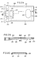
- the card carrier part 2 already mentioned several times is in 2A, 2B and 2C shown in detail and there designated by the reference number 2.
- the card carrier part 2 is formed in one piece; it points an unlocking section 21 and a card receiving section 22 on.
- the card receiving section 22 has, as in particular 2A can be seen, there by dashed lines Lines shown, tub-like serving as a card support surface Indentation 221 in which the card to be read can be used.
- the trough-like recess 221 is on the Adapted the shape of the card to be read; she teaches like that the card reader under consideration to be used as cards SIM modules have a so-called coding slope 222, through which an incorrectly oriented insertion of the SIM module should be prevented in the trough-like recess 221.
- the trough-like recess 221 has, as in particular FIGS. 2A and 2B show openings in their base 223 and 224, which make it possible to insert one into the trough-like depression 221 inserted card from beyond of the bottom from the trough-like depression 221 and remove from the card carrier part 2.
- Tongue-like element 225 designed to be deformable (bendable) from which is at least partially over the tub-like Recess 221 extends.
- the distance between the tongue-like element 225 and the The bottom of the trough-like depression 221 corresponds approximately to that Thickness of the card to be used there.
- the tongue-like element 225 is, as already mentioned above was designed to be elastically bendable. That is, for insertion the card between the tongue-like element 225 and the bottom of the trough-like recess 221 can be bend tongue-like element 225 elastically, and in used as intended in the trough-like recess 221 The state of the card presses the tongue-like element 225 the card against the bottom of the trough-like depression 221. This clamping action of the tongue-like element 225 and further the fact that the tub-like Indentation 221 to the shape of the card (s) to be read is adapted, lend the card in the intended use State one against all directions Sliding or moving secured seat.
- the card carrier part 2 Once used as intended in the card carrier part 2 The card can no longer take the position it is without leave a very specific external influence. That is the one to be read Card-containing card carrier part 2 can therefore in the Contact carrier part 1 can be inserted without the card suddenly stands in the way. Damage to the Card and / or the card reader due to correct inserted, but then slipped or shifted Cards are therefore reliably excluded.
- the tongue-like element 221 is preferably in one place provided which is adjacent to the coding slope 222 the trough-like recess 221.
- the coding slope is preferably arranged such that inserting the card to be read with its coding slope requires advance.
- the card will be in such a way assembled card carrier part inserted incorrectly, so strikes a section having no coding slope the card against the coding slope 222 of the tub-like Indentation 221 and can no longer be inserted will.
- the card If the card is struck at the coding slope 222 already partially under the tongue-like element 225 is reached, it can be used with no coding slope having section also not on the coding slope 222 come to rest; this is recognizable by the only in about the thickness of the map corresponding distance between the tongue-like element 225 and the bottom of the tub-like Depression 221 prevented.
- the card is on when it is struck the coding slope 222, however, not yet under the tongue-like Element 225 arrives, it can with the none Section having a coding slope on the coding slope 222 of the trough-like depression 221 come to rest, however, this can in turn easily be regarded as improper Position of the map can be recognized.
- the tongue-like element 225 has proven to be favorable to arrange and / or train that card only then between the tongue-like element 225 and the bottom of the trough-like depression 221 can reach if tried the card is correctly oriented into the trough-like recess 221 to be used.
- the arrangement shown in Figure 2 of the tongue-like element 225 for example accomplished by a correspondingly short training of the same will.
- the tongue-like Element is attached and / or designed in such a way that the map is only between a very specific direction the tongue-like element 225 and the bottom of the tub-like Recess 221 can be inserted.
- the card pad not only formed and limited by the trough-like recess 221 can be.
- the card support surface also by completely or partially revolving Bridges, wall-like elevations or the like can be defined.
- the Card receiving section 22 at the insertion of the Card carrier part 2 in the contact carrier part 1 the raised Edge sections 112 of the contact carrier part 1 facing sides raised edge portions 226.
- the edge sections 226 are designed on the outside in such a way that that when inserting the card carrier part 2 into the contact carrier part 1 in the groove-like recesses 113 of the Contact carrier part 1 run and be guided in this.
- the inward-facing areas of the edge sections are as can be seen in particular from FIGS. 2B and 2C, provided with elevations 227 and 228 positioned in this way and are designed so that when you insert the card carrier part 2 in the contact carrier part 1 via the elevations 132 and 133 of the plate 13 of the contact carrier part 1 run away and accompanying the plate 13 together with the dome-like end sections 122 of the contact springs 12 of the Press contact carrier part 1 out of the insertion path.
- the surveys 227 and 228 of the card carrier part 1 are like that Elevations 132 and 133 of the contact carrier part 1 with bevels Mistake.
- the card carrier part 2 more precisely its card receiving section 22 points to the direction of insertion front end one or more locking elements in the form of locking recesses 229, which in the contact carrier part 1 inserted state of the card carrier part 2 with the locking lugs 114 of the contact carrier part 1 and thereby lock unintentional removal of the card carrier part 2 from the Prevent contact carrier part 1.
- the unlocking section 21 is elastically deformable by two (Bendable) connecting elements 211 and 212 with the Card receiving section 22 connected. Except for the fasteners 211 and 212 has the unlocking section 21 two more rocker arms 213 and 214 and a rocker arm operating portion provided between them on; the connecting elements 211 and 212 are with the arms of the rocker arms 213 and 214 facing away from each other connected.
- the rocker arms 213 and 214 have support elements 215 and 216, respectively on, which is inserted into the contact carrier part 1 of the card carrier part 2 on the contact carrier part 1.
- the rocker arm operating section consists of a compressive force attachment section 217 and two elastically deformable (bendable) connectors 218 and 219; the fasteners 218 and 219 connect the pressure force attachment section 217 with the arms of the rocker arms facing each other 213 and 214, respectively.
- This mechanism takes place in that the pressure force attachment portion 217 (accessible from the outside) a pressure force is exerted. This can be done, for example Pushing a ballpoint pen or the like into an im Press force attachment portion 217 provided recess will.
- the card receiving section 22 By pulling the card receiving section 22 come the locking elements 114 and 229 disengaged, and get more or less at the same time the elevations 227 and 228 of the card carrier part 2 over the elevations 132 and 133 of the plate 13 of the contact carrier part 1. As a result, the card carrier part 2 (the card receiving portion 22) thereby pushing the plate away 13 pulled out a piece from the contact carrier part 1.
- the plate 13 and the contact springs 12 are here as when inserting the Card part 2 in the contact carrier part 1 in one of the Card surface held spaced position.
- the card inserted into the card carrier part 2 remains when inserting the card carrier part 2 into the contact carrier part 1 as well as when removing the card carrier part 2 the contact carrier part 1 always in its intended Position within the card carrier part 2.
- the danger of Damage to the card to be read and / or the card reading device when pushing and disconnecting the contact carrier part 1 and card carrier part 2 is almost complete eliminable.
Landscapes
- Engineering & Computer Science (AREA)
- Artificial Intelligence (AREA)
- Computer Vision & Pattern Recognition (AREA)
- Physics & Mathematics (AREA)
- General Physics & Mathematics (AREA)
- Theoretical Computer Science (AREA)
- Conveying Record Carriers (AREA)
- Details Of Connecting Devices For Male And Female Coupling (AREA)
- Coupling Device And Connection With Printed Circuit (AREA)
- Telephone Set Structure (AREA)
Applications Claiming Priority (2)
| Application Number | Priority Date | Filing Date | Title |
|---|---|---|---|
| DE19638648 | 1996-09-20 | ||
| DE19638648 | 1996-09-20 |
Publications (2)
| Publication Number | Publication Date |
|---|---|
| EP0833271A2 true EP0833271A2 (fr) | 1998-04-01 |
| EP0833271A3 EP0833271A3 (fr) | 1998-06-17 |
Family
ID=7806386
Family Applications (1)
| Application Number | Title | Priority Date | Filing Date |
|---|---|---|---|
| EP97114642A Withdrawn EP0833271A3 (fr) | 1996-09-20 | 1997-08-22 | Lecteur de cartes à puce |
Country Status (3)
| Country | Link |
|---|---|
| US (1) | US6050492A (fr) |
| EP (1) | EP0833271A3 (fr) |
| JP (1) | JPH10124628A (fr) |
Families Citing this family (7)
| Publication number | Priority date | Publication date | Assignee | Title |
|---|---|---|---|---|
| US6705529B1 (en) * | 1998-11-26 | 2004-03-16 | Nokia Mobile Phones, Ltd. | Data card holder and reader therefor |
| FI991002A (fi) * | 1999-05-03 | 2000-11-04 | Nokia Mobile Phones Ltd | Toimikorttiliitin ja matkaviestin |
| GB2352315B (en) * | 1999-07-19 | 2003-12-03 | Nokia Mobile Phones Ltd | Sim card reader |
| US7093764B1 (en) | 2001-04-20 | 2006-08-22 | Palm, Inc. | Integrated SIM holder with backcase and rotating door |
| CN102685276B (zh) * | 2011-03-11 | 2015-03-18 | 索尼爱立信移动通讯有限公司 | 具有防呆功能的sim卡槽和包括该sim卡槽的电子设备 |
| CN104300321B (zh) | 2013-07-18 | 2016-10-05 | 美国莫列斯股份有限公司 | 电子卡连接装置及电子装置 |
| JP2017107745A (ja) * | 2015-12-10 | 2017-06-15 | Smk株式会社 | カードコネクタ |
Citations (3)
| Publication number | Priority date | Publication date | Assignee | Title |
|---|---|---|---|---|
| EP0414390A1 (fr) * | 1989-08-19 | 1991-02-27 | Nokia Mobile Phones (U.K.) Limited | Lecteur de cartes |
| US5036184A (en) * | 1987-11-27 | 1991-07-30 | Nhk Spring Co., Ltd. | Card reader using linear card conveyer means |
| DE4138342A1 (de) * | 1990-11-26 | 1992-05-27 | Motorola Inc | Vorrichtung zur annahme und zum festhalten einer speicher-karte |
Family Cites Families (5)
| Publication number | Priority date | Publication date | Assignee | Title |
|---|---|---|---|---|
| US3947666A (en) * | 1974-08-09 | 1976-03-30 | Drake Manufacturing Company | Card reader |
| DE3343727A1 (de) * | 1983-12-02 | 1985-06-13 | Siemens AG, 1000 Berlin und 8000 München | Kartenleser fuer kassiervorrichtungen |
| DE4008655C2 (de) * | 1990-01-30 | 2001-03-22 | Amphenol Tuchel Elect | Kontaktiereinrichtung, insbesondere für ein Sim |
| DE4029576C2 (de) * | 1990-09-18 | 1994-12-01 | Amphenol Tuchel Elect | Kontaktiereinrichtung für Standard-Chipkarte und SIM-Karte |
| FR2692062B1 (fr) * | 1992-06-04 | 1994-09-09 | Sagem | Récepteur de carte permettant l'éjection d'une carte cassée et lecteur de carte l'utilisant. |
-
1997
- 1997-08-22 EP EP97114642A patent/EP0833271A3/fr not_active Withdrawn
- 1997-09-19 JP JP9273839A patent/JPH10124628A/ja not_active Withdrawn
- 1997-09-22 US US08/935,146 patent/US6050492A/en not_active Expired - Lifetime
Patent Citations (3)
| Publication number | Priority date | Publication date | Assignee | Title |
|---|---|---|---|---|
| US5036184A (en) * | 1987-11-27 | 1991-07-30 | Nhk Spring Co., Ltd. | Card reader using linear card conveyer means |
| EP0414390A1 (fr) * | 1989-08-19 | 1991-02-27 | Nokia Mobile Phones (U.K.) Limited | Lecteur de cartes |
| DE4138342A1 (de) * | 1990-11-26 | 1992-05-27 | Motorola Inc | Vorrichtung zur annahme und zum festhalten einer speicher-karte |
Also Published As
| Publication number | Publication date |
|---|---|
| JPH10124628A (ja) | 1998-05-15 |
| EP0833271A3 (fr) | 1998-06-17 |
| US6050492A (en) | 2000-04-18 |
Similar Documents
| Publication | Publication Date | Title |
|---|---|---|
| DE3943703C2 (de) | Chipkartenleser | |
| EP0849695A2 (fr) | Partie d'un porteur de carte | |
| DE3937383A1 (de) | Aufnahmevorrichtung fuer chipkarten | |
| EP1398723A2 (fr) | Dispositif à contacts pour une carte à puce, en particulier pour une carte SIM | |
| EP2026241B1 (fr) | Dispositif de lecture de carte SIM modulaire doté d'un tiroir à ressort | |
| DE3810274A1 (de) | Chipkarten-kontaktiereinrichtung | |
| EP1738294B1 (fr) | Connecteur de carte puce, dot notamment d'un dispositif de protection | |
| EP0833268A2 (fr) | Dispositif de lecture de carte | |
| EP0493522B1 (fr) | Lecteur de carte a puce | |
| EP2002379B1 (fr) | Lecteur de cartes selon le systeme push-push | |
| EP2659425B1 (fr) | Connecteur de carte intelligente avec contact basculant | |
| EP0894310B1 (fr) | Dispositif de lecture de cartes | |
| EP0731415B1 (fr) | Boítier pour carte à puce | |
| EP0833271A2 (fr) | Lecteur de cartes à puce | |
| WO2007025758A1 (fr) | Connecteur de carte intelligente comportant un dispositif de protection conçu pour des cartes a faible espacement | |
| EP0833272A2 (fr) | Lecteur de carte à puce | |
| DE102007057521B4 (de) | Smart-Card-Connector mit Schirmeinrichtung | |
| DE19703007C2 (de) | Kartenlesevorrichtung | |
| DE102011100338B4 (de) | Kartenkontaktiervorrichtung für eine Mini UICC-Karte | |
| DE2554177A1 (de) | Schaltelement | |
| DE10003068B4 (de) | SIM-Kartenkontaktiereinrichtung mit quer angeordnetem Deckel | |
| DE19934964C1 (de) | Kontaktiereinrichtung | |
| WO2000041126A1 (fr) | Interrupteur universel pour lecteur de carte a puce | |
| DE10041862A1 (de) | Kartenanwesenheitsschalter mit Auswurffunktion für Smart Card Connector | |
| DE20212809U1 (de) | Kontaktiervorrichtung für eine Chipkarte, insbesondere für eine SIM-Karte |
Legal Events
| Date | Code | Title | Description |
|---|---|---|---|
| PUAI | Public reference made under article 153(3) epc to a published international application that has entered the european phase |
Free format text: ORIGINAL CODE: 0009012 |
|
| AK | Designated contracting states |
Kind code of ref document: A2 Designated state(s): BE CH DE DK FI FR GB IT LI NL SE |
|
| AX | Request for extension of the european patent |
Free format text: AL;LT;LV;RO;SI |
|
| PUAL | Search report despatched |
Free format text: ORIGINAL CODE: 0009013 |
|
| AK | Designated contracting states |
Kind code of ref document: A3 Designated state(s): AT BE CH DE DK ES FI FR GB GR IE IT LI LU MC NL PT SE |
|
| AX | Request for extension of the european patent |
Free format text: AL;LT;LV;RO;SI |
|
| 17P | Request for examination filed |
Effective date: 19980707 |
|
| AKX | Designation fees paid |
Free format text: BE CH DE DK FI FR GB IT LI NL SE |
|
| RBV | Designated contracting states (corrected) |
Designated state(s): BE CH DE DK FI FR GB IT LI NL SE |
|
| RAP1 | Party data changed (applicant data changed or rights of an application transferred) |
Owner name: TYCO ELECTRONICS LOGISTICS AG |
|
| 17Q | First examination report despatched |
Effective date: 20030513 |
|
| STAA | Information on the status of an ep patent application or granted ep patent |
Free format text: STATUS: THE APPLICATION IS DEEMED TO BE WITHDRAWN |
|
| 18D | Application deemed to be withdrawn |
Effective date: 20030924 |