EP0833271A2 - Chipcard reader - Google Patents
Chipcard reader Download PDFInfo
- Publication number
- EP0833271A2 EP0833271A2 EP97114642A EP97114642A EP0833271A2 EP 0833271 A2 EP0833271 A2 EP 0833271A2 EP 97114642 A EP97114642 A EP 97114642A EP 97114642 A EP97114642 A EP 97114642A EP 0833271 A2 EP0833271 A2 EP 0833271A2
- Authority
- EP
- European Patent Office
- Prior art keywords
- card
- carrier part
- tongue
- reading device
- trough
- Prior art date
- Legal status (The legal status is an assumption and is not a legal conclusion. Google has not performed a legal analysis and makes no representation as to the accuracy of the status listed.)
- Withdrawn
Links
Images

Classifications
-
- G—PHYSICS
- G06—COMPUTING; CALCULATING OR COUNTING
- G06K—GRAPHICAL DATA READING; PRESENTATION OF DATA; RECORD CARRIERS; HANDLING RECORD CARRIERS
- G06K7/00—Methods or arrangements for sensing record carriers, e.g. for reading patterns
- G06K7/0013—Methods or arrangements for sensing record carriers, e.g. for reading patterns by galvanic contacts, e.g. card connectors for ISO-7816 compliant smart cards or memory cards, e.g. SD card readers
- G06K7/0021—Methods or arrangements for sensing record carriers, e.g. for reading patterns by galvanic contacts, e.g. card connectors for ISO-7816 compliant smart cards or memory cards, e.g. SD card readers for reading/sensing record carriers having surface contacts
Definitions
- the present invention relates to a card reading device according to the preamble of claim 1, i.e. a Card reader with a contact carrier part and Card carrier part, the card carrier part with a Card receiving section for receiving a card to be read trained and together with the card used there at least partially in or on the contact carrier part is slidable.
- Such card readers are, for example, those in Mobile phones used readers to answer and / or passing on by or for a so-called SIM card or a so-called SIM module provided Information.
- SIM modules are mainly used in cell phones used for participant identification; “SIM” is that Abbreviation for “Subscriber Identity Module”. SIM modules are especially due to their small dimensions (25 x 15 mm) very suitable for use in mobile phones.
- Card reading devices as claimed in claim 1
- card readers can also be used to read the type be "normal" chip cards.
- SIM modules that can be used in card readers, "normal" chip cards etc. are all chips containing Cards or smart cards and are the simplicity below for short referred to as cards; the process of receiving and / or passing on through an or Information provided for a card is below For convenience, referred to as reading the map.
- Card readers consisting of a contact carrier part and one in this or on this sliding card carrier part consist, among other things, are well suited for use in Cell phones. On the one hand, they are easy to use and, on the other hand, are very small in size.
- Card readers of this type are easy to use because the cards to be read are from the outside, that is without removing the battery (cell phone) or the like can be inserted into the card reading devices.
- Card readers of this type are small, for example because essentially by one special design of the card carrier part, ie without large and complex mechanics can be prevented that the for contacting the contact elements provided for reading the card of the contact carrier part during insertion and removing the card to be read into and out of Contact carrier part can be short-circuited by the card.
- the present invention is therefore based on the object the card reading device according to the preamble of the claim 1 in such a way that damage to the reading card and / or the card reader when inserting of the card carrier part containing the card to be read can be reliably prevented in the contact carrier part.
- the card carrier part itself at least partially across the card receiving section extending, elastically deformable tongue-like element having.
- the tongue-like element By providing the tongue-like element, the can reading card no longer simply by hanging up as usual on a card support surface adapted to the shape of the card of the card receiving section in their intended Position to be brought; rather, it must be between inserted the tongue-like element and the card support surface to be used as intended in the card carrier part to be able to be used. This is in several ways advantageous.
- the card is under the tongue-like element inserted state between this and the card support surface can be clamped and thus against an unwanted Leaving this position is secured.
- the intended card inserted in the card carrier part therefore - unlike conventional card readers the case is - the insertion of the card carrier part not in the way of the contact carrier part, so that damage to the card and / or the card reader due to correctly inserted, but then slipped Cards can be reliably excluded.
- tongue-like Elements Another advantage provided by the tongue-like Elements can be achieved is that an improper Insert the card into the card carrier part either completely excluded or at least not difficult immediately is recognizable. For example, trying the card without being inserted under the tongue-like element in the Insert card receiving section, so the card comes loose to lie on the tongue-like element, which immediately beyond doubt as an improper position of the Card is identifiable. On the other hand, an attempt is made to encoded, i.e. a a coding slope or the like card with the wrong orientation, so can these not, or at least not entirely, under that tongue-like element can be pushed, which is also not difficult can be seen.
- the user of the card reading device according to the invention can in both cases at first glance recognize that the card is not in the card carrier part as intended is used and will therefore not try at all the card carrier part into the contact carrier part push. This also damages the card and / or the card reader due to incorrectly inserted cards can be reliably excluded.
- a card reading device was therefore created in damage to the card to be read and / or the card reading device when inserting the card to be read card carrier part contained in the contact carrier part as far as possible excluded are.
- the card reader described below is one Card reading device designed for reading SIM modules. However, this does not mean that the invention is based on this designed card readers is limited; The invention can also be used with card readers that designed for reading any other cards (chip cards) are.
- the card reading device described consists in the considered Example of a contact carrier part and a card carrier part; the one to be read by the card reader Card is inserted into the card carrier part and together with this inserted into the contact carrier part.
- FIGS. 1A, 1B and 1C Said contact carrier part is shown in FIGS. 1A, 1B and 1C shown; it is designated there by reference number 1.
- the contact carrier part 1 consists of an insulating body 11, six contact elements in the form of contact springs 12 and one Contact element position change element in the form of a Plate 13.
- FIG. 1A and 1B are also by dashed lines Parts of the later, in particular with reference to FIG. 2 Card carrier part 2 described in more detail in the contact carrier part 1 inserted state shown.
- the contact carrier part 1, more precisely the insulating body 11 and the contact springs 12 are for mounting on one Electrical circuit board (not shown in the figures) designed.
- the insulating body 11 shows how 1A and 1B can be seen in particular, Mounting pin 111, which in corresponding recesses insertable in the electrical circuit board and if required can also be fastened there; the contact springs 12 are on each one of its ends is formed as a solder tail 121, which for example using an SMT soldering process the circuit board are solderable.
- the insulating body 11 is that part of the contact carrier part 1, this, more specifically its further Holds components together and a proper interaction the same with the card carrier part 2 enables.
- the latter function of the insulating body 11 can this in particular by providing groove-like recesses 113 in raised edge portions 112 on opposite one another Meet sides of the insulator 11; the (facing each other) groove-like recesses 113 can, in particular can be seen from Figure 1C, as a guide for that with the contact carrier part 1 (by a stack or an interlocking) to be engaged, later still serve card carrier part 2 described in more detail.
- the contact springs 12 each have a dome-shaped, elastically deformable (movable) end section 122 on.
- This end section 122 is that part in each case the contact springs 12, with which these with the contact surfaces (Surface contacts) of the card (s) to be read in Come in contact.
- the Contact springs 12 partially covered by the plate 13.
- the Plate 13 has recesses 131 through which the end portions 122 of the contact springs 12 can protrude.
- the recesses 131 are positioned such that the end portions 122 of the contact springs exactly with the contact surfaces of the card to be read meet if they are within the card reading device is in its reading position.
- a SIM module is provided, a total of six contact springs 12, which include two, three contact springs 12 each Rows are arranged.
- the plate 13 has at its raised edge portions 112 of the insulating body 11 facing sides elevations 132 and 133, which are essentially parallel to the raised edge portions 112 at a short distance from these extend and, as in particular from Figures 1B and 1C can be seen, in part that in the edge sections 112 cover provided groove-like recesses 113.
- the elevations 132 and 133 of the plate 13 are when inserted the card carrier part 2 in the groove-like recesses 113 of the contact carrier part 1 in the way.
- plate 13 can, as will be described in more detail is from the card carrier part 2 to the circuit board be pushed down the path. This has two effects: the card carrier part 2 can then be essentially unimpeded are inserted into the contact carrier part 1, and on the other hand, by pushing the plate 13 away only this itself, but also the contact springs 12 (in particular the end portions 122) pushed away.
- the contact springs 12 are pushed away by the pushing away causes plate 13; the contact springs 12, more precisely in particular, their end sections 122 are removed from the plate 13 taken away.
- Pushing the plate 13 away through the card carrier part 2 is caused by elevations of the card carrier part 2, which when inserting the card carrier part 2 into the contact carrier part 1 via the elevations 132 and 133 of the plate 13 running away pushing them away. So the surveys the card support part 2, which is inherently on the are at the same height as the elevations 132 and 133 of the plate 13, can run over them with little resistance elevations 132 and 133, as in particular from FIG. 1B can be seen, at their front and rear ends, bevels on.
- the contact carrier part 2 more precisely the insulating body 11 of the same or several locking elements in the form of locking lugs 114, which in completely inserted into the contact carrier part 1 the card carrier part 2 with associated locking elements Lock (locking recesses) of the card carrier part 2.
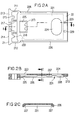
- the card carrier part 2 already mentioned several times is in 2A, 2B and 2C shown in detail and there designated by the reference number 2.
- the card carrier part 2 is formed in one piece; it points an unlocking section 21 and a card receiving section 22 on.
- the card receiving section 22 has, as in particular 2A can be seen, there by dashed lines Lines shown, tub-like serving as a card support surface Indentation 221 in which the card to be read can be used.
- the trough-like recess 221 is on the Adapted the shape of the card to be read; she teaches like that the card reader under consideration to be used as cards SIM modules have a so-called coding slope 222, through which an incorrectly oriented insertion of the SIM module should be prevented in the trough-like recess 221.
- the trough-like recess 221 has, as in particular FIGS. 2A and 2B show openings in their base 223 and 224, which make it possible to insert one into the trough-like depression 221 inserted card from beyond of the bottom from the trough-like depression 221 and remove from the card carrier part 2.
- Tongue-like element 225 designed to be deformable (bendable) from which is at least partially over the tub-like Recess 221 extends.
- the distance between the tongue-like element 225 and the The bottom of the trough-like depression 221 corresponds approximately to that Thickness of the card to be used there.
- the tongue-like element 225 is, as already mentioned above was designed to be elastically bendable. That is, for insertion the card between the tongue-like element 225 and the bottom of the trough-like recess 221 can be bend tongue-like element 225 elastically, and in used as intended in the trough-like recess 221 The state of the card presses the tongue-like element 225 the card against the bottom of the trough-like depression 221. This clamping action of the tongue-like element 225 and further the fact that the tub-like Indentation 221 to the shape of the card (s) to be read is adapted, lend the card in the intended use State one against all directions Sliding or moving secured seat.
- the card carrier part 2 Once used as intended in the card carrier part 2 The card can no longer take the position it is without leave a very specific external influence. That is the one to be read Card-containing card carrier part 2 can therefore in the Contact carrier part 1 can be inserted without the card suddenly stands in the way. Damage to the Card and / or the card reader due to correct inserted, but then slipped or shifted Cards are therefore reliably excluded.
- the tongue-like element 221 is preferably in one place provided which is adjacent to the coding slope 222 the trough-like recess 221.
- the coding slope is preferably arranged such that inserting the card to be read with its coding slope requires advance.
- the card will be in such a way assembled card carrier part inserted incorrectly, so strikes a section having no coding slope the card against the coding slope 222 of the tub-like Indentation 221 and can no longer be inserted will.
- the card If the card is struck at the coding slope 222 already partially under the tongue-like element 225 is reached, it can be used with no coding slope having section also not on the coding slope 222 come to rest; this is recognizable by the only in about the thickness of the map corresponding distance between the tongue-like element 225 and the bottom of the tub-like Depression 221 prevented.
- the card is on when it is struck the coding slope 222, however, not yet under the tongue-like Element 225 arrives, it can with the none Section having a coding slope on the coding slope 222 of the trough-like depression 221 come to rest, however, this can in turn easily be regarded as improper Position of the map can be recognized.
- the tongue-like element 225 has proven to be favorable to arrange and / or train that card only then between the tongue-like element 225 and the bottom of the trough-like depression 221 can reach if tried the card is correctly oriented into the trough-like recess 221 to be used.
- the arrangement shown in Figure 2 of the tongue-like element 225 for example accomplished by a correspondingly short training of the same will.
- the tongue-like Element is attached and / or designed in such a way that the map is only between a very specific direction the tongue-like element 225 and the bottom of the tub-like Recess 221 can be inserted.
- the card pad not only formed and limited by the trough-like recess 221 can be.
- the card support surface also by completely or partially revolving Bridges, wall-like elevations or the like can be defined.
- the Card receiving section 22 at the insertion of the Card carrier part 2 in the contact carrier part 1 the raised Edge sections 112 of the contact carrier part 1 facing sides raised edge portions 226.
- the edge sections 226 are designed on the outside in such a way that that when inserting the card carrier part 2 into the contact carrier part 1 in the groove-like recesses 113 of the Contact carrier part 1 run and be guided in this.
- the inward-facing areas of the edge sections are as can be seen in particular from FIGS. 2B and 2C, provided with elevations 227 and 228 positioned in this way and are designed so that when you insert the card carrier part 2 in the contact carrier part 1 via the elevations 132 and 133 of the plate 13 of the contact carrier part 1 run away and accompanying the plate 13 together with the dome-like end sections 122 of the contact springs 12 of the Press contact carrier part 1 out of the insertion path.
- the surveys 227 and 228 of the card carrier part 1 are like that Elevations 132 and 133 of the contact carrier part 1 with bevels Mistake.
- the card carrier part 2 more precisely its card receiving section 22 points to the direction of insertion front end one or more locking elements in the form of locking recesses 229, which in the contact carrier part 1 inserted state of the card carrier part 2 with the locking lugs 114 of the contact carrier part 1 and thereby lock unintentional removal of the card carrier part 2 from the Prevent contact carrier part 1.
- the unlocking section 21 is elastically deformable by two (Bendable) connecting elements 211 and 212 with the Card receiving section 22 connected. Except for the fasteners 211 and 212 has the unlocking section 21 two more rocker arms 213 and 214 and a rocker arm operating portion provided between them on; the connecting elements 211 and 212 are with the arms of the rocker arms 213 and 214 facing away from each other connected.
- the rocker arms 213 and 214 have support elements 215 and 216, respectively on, which is inserted into the contact carrier part 1 of the card carrier part 2 on the contact carrier part 1.
- the rocker arm operating section consists of a compressive force attachment section 217 and two elastically deformable (bendable) connectors 218 and 219; the fasteners 218 and 219 connect the pressure force attachment section 217 with the arms of the rocker arms facing each other 213 and 214, respectively.
- This mechanism takes place in that the pressure force attachment portion 217 (accessible from the outside) a pressure force is exerted. This can be done, for example Pushing a ballpoint pen or the like into an im Press force attachment portion 217 provided recess will.
- the card receiving section 22 By pulling the card receiving section 22 come the locking elements 114 and 229 disengaged, and get more or less at the same time the elevations 227 and 228 of the card carrier part 2 over the elevations 132 and 133 of the plate 13 of the contact carrier part 1. As a result, the card carrier part 2 (the card receiving portion 22) thereby pushing the plate away 13 pulled out a piece from the contact carrier part 1.
- the plate 13 and the contact springs 12 are here as when inserting the Card part 2 in the contact carrier part 1 in one of the Card surface held spaced position.
- the card inserted into the card carrier part 2 remains when inserting the card carrier part 2 into the contact carrier part 1 as well as when removing the card carrier part 2 the contact carrier part 1 always in its intended Position within the card carrier part 2.
- the danger of Damage to the card to be read and / or the card reading device when pushing and disconnecting the contact carrier part 1 and card carrier part 2 is almost complete eliminable.
Landscapes
- Engineering & Computer Science (AREA)
- Artificial Intelligence (AREA)
- Computer Vision & Pattern Recognition (AREA)
- Physics & Mathematics (AREA)
- General Physics & Mathematics (AREA)
- Theoretical Computer Science (AREA)
- Conveying Record Carriers (AREA)
- Details Of Connecting Devices For Male And Female Coupling (AREA)
- Coupling Device And Connection With Printed Circuit (AREA)
- Telephone Set Structure (AREA)
Abstract
Description
Die vorliegende Erfindung betrifft eine Kartenlesevorrichtung gemäß dem Oberbegriff des Patentanspruchs 1, d.h. eine Kartenlesevorrichtung mit einem Kontaktträgerteil und einem Kartenträgerteil, wobei das Kartenträgerteil mit einem Kartenaufnahmeabschnitt zur Aufnahme einer zu lesenden Karte ausgebildet und zusammen mit der dort eingesetzten Karte zumindest teilweise in das oder auf das Kontaktträgerteil schiebbar ist.The present invention relates to a card reading device according to the preamble of claim 1, i.e. a Card reader with a contact carrier part and Card carrier part, the card carrier part with a Card receiving section for receiving a card to be read trained and together with the card used there at least partially in or on the contact carrier part is slidable.
Derartige Kartenlesevorrichtungen sind beispielsweise die in Mobiltelefonen verwendeten Lesevorrichtungen zum Entgegennehmen und/oder Weitergeben von durch eine oder für eine sogenannte SIM-Karte bzw. ein sogenanntes SIM-Modul bereitgestellten Informationen.Such card readers are, for example, those in Mobile phones used readers to answer and / or passing on by or for a so-called SIM card or a so-called SIM module provided Information.
Die besagten SIM-Module werden in Mobiltelefonen vor allem zur Teilnehmeridentifizierung eingesetzt; "SIM" ist die Abkürzung für "Subscriber Identity Module". SIM-Module sind insbesondere aufgrund ihrer geringen Abmessungen (25 x 15 mm) sehr gut für den Einsatz in Mobiltelefonen geeignet.Said SIM modules are mainly used in cell phones used for participant identification; "SIM" is that Abbreviation for "Subscriber Identity Module". SIM modules are especially due to their small dimensions (25 x 15 mm) very suitable for use in mobile phones.
Kartenlesevorrichtungen der im Patentanspruch 1 beanspruchten Art können jedoch auch Kartenlesevorrichtungen zum Lesen der "normalen" Chipkarten sein.Card reading devices as claimed in claim 1 However, card readers can also be used to read the type be "normal" chip cards.
Die in Kartenlesevorrichtungen verwendbaren SIM-Module, "normalen" Chipkarten etc. sind allesamt Chips enthaltende Karten bzw. Chipkarten und werden im folgenden der Einfachheit halber kurz als Karten bezeichnet; der Vorgang des Entgegennehmens und/oder des Weitergebens von durch eine oder für eine Karte bereitgestellten Informationen wird nachfolgend der Einfachheit halber als Lesen der Karte bezeichnet. The SIM modules that can be used in card readers, "normal" chip cards etc. are all chips containing Cards or smart cards and are the simplicity below for short referred to as cards; the process of receiving and / or passing on through an or Information provided for a card is below For convenience, referred to as reading the map.
Kartenlesevorrichtungen, die aus einem Kontaktträgerteil und einem in dieses oder auf dieses schiebbaren Kartenträgerteil bestehen, eignen sich unter anderem gut für den Einsatz in Mobiltelefonen. Sie sind nämlich einerseits leicht zu bedienen und weisen andererseits nur eine sehr geringe Größe auf.Card readers consisting of a contact carrier part and one in this or on this sliding card carrier part consist, among other things, are well suited for use in Cell phones. On the one hand, they are easy to use and, on the other hand, are very small in size.
Leicht zu bedienen sind derartige Kartenlesevorrichtungen deshalb, weil die zu lesenden Karten jeweils von außen, also ohne Abnehmen der Batterie (des Mobiltelefons) oder dergleichen in die Kartenlesevorrichtungen einbringbar sind.Card readers of this type are easy to use because the cards to be read are from the outside, that is without removing the battery (cell phone) or the like can be inserted into the card reading devices.
Klein auszubilden sind derartige Kartenlesevorrichtungen beispielsweise deshalb, weil im wesentlichen allein durch eine besondere Ausgestaltung des Kartenträgerteils, also ohne große und aufwendige Mechanik verhindert werden kann, daß die zum Kontaktieren der zu lesenden Karte vorgesehenen Kontaktelemente des Kontaktträgerteils während des Einschiebens und des Entfernens der zu lesenden Karte in das bzw. aus dem Kontaktträgerteil durch die Karte kurzgeschlossen werden.Card readers of this type are small, for example because essentially by one special design of the card carrier part, ie without large and complex mechanics can be prevented that the for contacting the contact elements provided for reading the card of the contact carrier part during insertion and removing the card to be read into and out of Contact carrier part can be short-circuited by the card.
Beim Gebrauch der bekannten Kartenlesevorrichtungen dieser Art kommt es jedoch bisweilen vor, daß die zu lesende Karte und/oder die Kartenlesevorrichtung beim Einschieben des die zu lesende Karte enthaltenen Kartenträgerteils in das Kontaktträgerteil beschädigt werden.When using the known card readers of this However, it sometimes happens that the card to be read and / or the card reader when inserting the card carrier part contained in the card to be read Contact carrier part can be damaged.
Der vorliegenden Erfindung liegt daher die Aufgabe zugrunde, die Kartenlesevorrichtung gemäß dem Oberbegriff des Patentanspruchs 1 derart weiterzubilden, daß Beschädigungen der zu lesenden Karte und/oder der Kartenlesevorrichtung beim Einschieben des die zu lesende Karte enthaltenen Kartenträgerteils in das Kontaktträgerteil zuverlässig verhinderbar sind.The present invention is therefore based on the object the card reading device according to the preamble of the claim 1 in such a way that damage to the reading card and / or the card reader when inserting of the card carrier part containing the card to be read can be reliably prevented in the contact carrier part.
Diese Aufgabe wird erfindungsgemäß durch die im kennzeichnenden Teil des Patentanspruchs 1 beanspruchten Merkmale gelöst. This object is achieved by the characterizing Part of claim 1 claimed features solved.
Demnach ist vorgesehen, daß das Kartenträgerteil ein sich zumindest teilweise über den Kartenaufnahmeabschnitt hinweg erstreckendes, elastisch verformbares zungenartiges Element aufweist.Accordingly, it is provided that the card carrier part itself at least partially across the card receiving section extending, elastically deformable tongue-like element having.
Durch das Vorsehen des zungenartigen Elements kann die zu lesende Karte nicht mehr wie bisher üblich einfach durch Auflegen auf eine an die Kartenform angepaßte Kartenauflagefläche des Kartenaufnahmeabschnittes in ihre bestimmungsgemäße Position gebracht werden; sie muß vielmehr zwischen das zungenartige Element und die Kartenauflagefläche eingeschoben werden, um bestimmungsgemäß ins Kartenträgerteil eingesetzt werden zu können. Dies ist in mehrfacher Hinsicht vorteilhaft.By providing the tongue-like element, the can reading card no longer simply by hanging up as usual on a card support surface adapted to the shape of the card of the card receiving section in their intended Position to be brought; rather, it must be between inserted the tongue-like element and the card support surface to be used as intended in the card carrier part to be able to be used. This is in several ways advantageous.
Einer der Vorteile besteht darin, daß die Karte im unter das zungenartige Element eingeschobenen Zustand zwischen diesem und der Kartenauflagefläche einklemmbar und so gegen ein ungewolltes Verlassen dieser Position gesichert ist. Die bestimmungsgemäß in das Kartenträgerteil eingesetzte Karte kann daher - anders als es bei den herkömmlichen Kartenlesevorrichtungen der Fall ist - dem Einschieben des Kartenträgerteils in das Kontaktträgerteil nicht im Wege stehen, so daß Beschädigungen der Karte und/oder der Kartenlesevorrichtung aufgrund zwar richtig eingesetzter, dann aber verrutschter Karten zuverlässig ausschließbar sind.One of the advantages is that the card is under the tongue-like element inserted state between this and the card support surface can be clamped and thus against an unwanted Leaving this position is secured. The intended card inserted in the card carrier part therefore - unlike conventional card readers the case is - the insertion of the card carrier part not in the way of the contact carrier part, so that damage to the card and / or the card reader due to correctly inserted, but then slipped Cards can be reliably excluded.
Ein weiterer Vorteil, der durch das Vorsehen des zungenartigen Elements erzielbar ist, besteht darin, daß ein nicht bestimmungsgemäßes Einsetzen der Karte in das Kartenträgerteil entweder gänzlich ausgeschlossen oder zumindest unschwer sofort erkennbar ist. Wird beispielsweise versucht, die Karte ohne Einschieben unter das zungenartige Element in den Kartenaufnahmeabschnitt einzusetzen, so kommt die Karte lose auf dem zungenartigen Element zu liegen, was auf Anhieb zweifelsfrei als eine nicht bestimmungsgemäße Position der Karte identifizierbar ist. Wird andererseits versucht, eine codierte, d.h. eine eine Codierungsschräge oder dergleichen aufweisende Karte falsch orientiert einzusetzen, so kann diese nicht oder zumindest nicht vollständig unter das zungenartige Element geschoben werden, was ebenfalls unschwer zu erkennen ist. Der Benutzer der erfindungsgemäßen Kartenlesevorrichtung kann in beiden Fällen auf den ersten Blick erkennen, daß die Karte nicht bestimmungsgemäß in das Kartenträgerteil eingesetzt ist und wird daher überhaupt nicht versuchen, das Kartenträgerteil in das Kontaktträgerteil zu schieben. Dadurch sind auch Beschädigungen der Karte und/oder der Kartenlesevorrichtung aufgrund falsch eingesetzter Karten zuverlässig ausschließbar.Another advantage provided by the tongue-like Elements can be achieved is that an improper Insert the card into the card carrier part either completely excluded or at least not difficult immediately is recognizable. For example, trying the card without being inserted under the tongue-like element in the Insert card receiving section, so the card comes loose to lie on the tongue-like element, which immediately beyond doubt as an improper position of the Card is identifiable. On the other hand, an attempt is made to encoded, i.e. a a coding slope or the like card with the wrong orientation, so can these not, or at least not entirely, under that tongue-like element can be pushed, which is also not difficult can be seen. The user of the card reading device according to the invention can in both cases at first glance recognize that the card is not in the card carrier part as intended is used and will therefore not try at all the card carrier part into the contact carrier part push. This also damages the card and / or the card reader due to incorrectly inserted cards can be reliably excluded.
Es wurde folglich eine Kartenlesevorrichtung geschaffen, bei der Beschädigungen der zu lesenden Karte und/oder der Kartenlesevorrichtung beim Einschieben des die zu lesende Karte enthaltenen Kartenträgerteils in das Kontaktträgerteil weitestgehend ausgeschlossen sind.A card reading device was therefore created in damage to the card to be read and / or the card reading device when inserting the card to be read card carrier part contained in the contact carrier part as far as possible excluded are.
Vorteilhafte Weiterbildungen der Erfindung sind Gegenstand der Unteransprüche.Advantageous developments of the invention are the subject of subclaims.
Die Erfindung wird nachfolgend anhand eines Ausführungsbeispiel unter Bezugnahme auf die Zeichnung näher erläutert. Es zeigen
- Figur 1A
- eine Draufsicht auf ein Kontaktträgerteil einer erfindungsgemäß ausgebildeten Kartenlesevorrichtung,
- Figur 1B
- eine Schnittdarstellung des in der Figur 1A gezeigten Kontaktträgerteils (Schnitt längs einer in der Figur 1A gezeigten Linie A-A),
- Figur 1C
- eine Seitenansicht des in den Figuren 1A und 1B gezeigten Kontaktträgerteils,
- Figur 2A
- eine Draufsicht auf ein Kartenträgerteil der erfindungsgemäß ausgebildeten Kartenlesevorrichtung,
- Figur 2B
- eine Schnittdarstellung des in der Figur 2A gezeigten Kartenträgerteils (Schnitt längs einer in der Figur 2A gezeigten Linie B-B), und
- Figur 2C
- eine Schnittdarstellung des in den Figuren 2A und 2B gezeigten Kartenträgerteils (Schnitt längs einer in der Figur 2B gezeigten Linie C-C).
- Figure 1A
- 2 shows a plan view of a contact carrier part of a card reading device designed according to the invention,
- Figure 1B
- FIG. 2 shows a sectional illustration of the contact carrier part shown in FIG. 1A (section along a line AA shown in FIG. 1A),
- Figure 1C
- 2 shows a side view of the contact carrier part shown in FIGS. 1A and 1B,
- Figure 2A
- 2 shows a plan view of a card carrier part of the card reading device designed according to the invention,
- Figure 2B
- FIG. 2 shows a sectional illustration of the card carrier part shown in FIG. 2A (section along a line BB shown in FIG. 2A), and
- Figure 2C
- a sectional view of the card carrier part shown in Figures 2A and 2B (section along a line CC shown in Figure 2B).
Die im folgenden beschriebene Kartenlesevorrichtung ist eine zum Lesen von SIM-Modulen ausgelegte Kartenlesevorrichtung. Dies bedeutet jedoch nicht, daß die Erfindung auf hierfür ausgelegte Kartenlesevorrichtungen beschränkt ist; die Erfindung ist auch bei Kartenlesevorrichtungen einsetzbar, die zum Lesen beliebiger anderer Karten (Chipkarten) ausgelegt sind.The card reader described below is one Card reading device designed for reading SIM modules. However, this does not mean that the invention is based on this designed card readers is limited; The invention can also be used with card readers that designed for reading any other cards (chip cards) are.
Die beschriebene Kartenlesevorrichtung besteht im betrachteten Beispiel aus einem Kontaktträgerteil und einem Kartenträgerteil; die durch die Kartenlesevorrichtung zu lesende Karte wird in das Kartenträgerteil eingesetzt und zusammen mit diesem in das Kontaktträgerteil eingeschoben.The card reading device described consists in the considered Example of a contact carrier part and a card carrier part; the one to be read by the card reader Card is inserted into the card carrier part and together with this inserted into the contact carrier part.
Das genannte Kontaktträgerteil ist in den Figuren 1A, 1B und 1C gezeigt; es ist dort mit dem Bezugszeichen 1 bezeichnet.Said contact carrier part is shown in FIGS. 1A, 1B and 1C shown; it is designated there by reference number 1.
Das Kontaktträgerteil 1 besteht aus einem Isolierkörper 11,
sechs Kontaktelementen in Form von Kontaktfedern 12 und einem
Kontaktelementestellungsveränderungselement in Form einer
Platte 13.The contact carrier part 1 consists of an
In den Figuren 1A und 1B sind durch gestrichelte Linien auch
Teile des später insbesondere unter Bezugnahme auf Figur 2
näher beschriebenen Kartenträgerteils 2 im in das Kontaktträgerteil
1 eingeschobenen Zustand dargestellt.In Figures 1A and 1B are also by dashed lines
Parts of the later, in particular with reference to FIG. 2
Das Kontaktträgerteil 1, genauer gesagt der Isolierkörper 11
und die Kontaktfedern 12 desselben sind zur Montage auf einer
(in den Figuren nicht gezeigten) elektrischen Leiterplatte
ausgelegt. Der Isolierkörper 11 weist zu diesem Zweck, wie
insbesondere aus den Figuren 1A und 1B ersichtlich ist,
Montagezapfen 111 auf, welche in entsprechende Ausnehmungen
in der elektrischen Leiterplatte einsteckbar und bei Bedarf
dort auch befestigbar sind; die Kontaktfedern 12 sind an jeweils
einem ihrer Enden als Lötfahnen 121 ausgebildet, welche
beispielsweise unter Verwendung eines SMT-Lötverfahrens mit
der Leiterplatte verlötbar sind.The contact carrier part 1, more precisely the
Der Isolierkörper 11 ist derjenige Bestandteil des Kontaktträgerteils
1, der dieses, genauer gesagt dessen weitere
Bestandteile zusammenhält und ein bestimmungsgemäßes Zusammenwirken
derselben mit dem Kartenträgerteil 2 ermöglicht.The insulating
Die letztgenannte Funktion des Isolierkörpers 11 kann dieser
insbesondere durch Vorsehen nutenartiger Aussparungen 113 in
erhöhten Randabschnitten 112 an einander gegenüberliegenden
Seiten des Isolierkörpers 11 erfüllen; die (einander zugewandten)
nutenartigen Aussparungen 113 können, wie insbesondere
aus der Figur 1C ersichtlich ist, als Führung für
das mit dem Kontaktträgerteil 1 (durch ein Übereinander- bzw.
ein Ineinanderschieben) in Eingriff zu bringende, später noch
genauer beschriebene Kartenträgerteil 2 dienen. Die Richtung,
längs welcher das Kartenträgerteil 2 relativ zum Kontaktträgerteil
1 bewegt werden muß, um in dieses eingeschoben zu
werden, ist bei den Darstellungen gemäß den Figuren 1A und 1B
die horizontal nach rechts verlaufende Richtung und bei der
Darstellung gemäß der Figur 1C die frontal in die Zeichnungsebene
hinein verlaufende Richtung. The latter function of the insulating
Die Kontaktfedern 12 weisen jeweils einen kuppenartig ausgebildeten,
elastisch verformbaren (bewegbaren) Endabschnitt
122 auf. Dieser Endabschnitt 122 ist jeweils derjenige Teil
der Kontaktfedern 12, mit welchem diese mit den Kontaktflächen
(Oberflächenkontakten) der zu lesenden Karte(n) in
Kontakt kommen.The contact springs 12 each have a dome-shaped,
elastically deformable (movable)
Wie insbesondere aus der Figur 1A ersichtlich ist, sind die
Kontaktfedern 12 teilweise durch die Platte 13 bedeckt. Die
Platte 13 weist Aussparungen 131 auf, durch welche die Endabschnitte
122 der Kontaktfedern 12 hindurchragen können.As can be seen in particular from FIG. 1A, the
Contact springs 12 partially covered by the
Die Aussparungen 131 sind derart positioniert, daß die Endabschnitte
122 der Kontaktfedern genau mit den Kontaktflächen
der zu lesenden Karte zusammentreffen, wenn sich diese innerhalb
der Kartenlesevorrichtung in ihrer Lesestellung befindet.
Im betrachteten Beispiel sind, da die zu lesende Karte
ein SIM-Modul ist, insgesamt sechs Kontaktfedern 12 vorgesehen,
die in zwei, jeweils drei Kontaktfedern 12 umfassenden
Reihen angeordnet sind.The
Die Platte 13 weist an ihren den erhöhten Randabschnitten 112
des Isolierkörpers 11 zugewandten Seiten jeweils Erhebungen
132 und 133 auf, welche sich im wesentlichen parallel zu den
erhöhten Randabschnitten 112 in geringem Abstand zu diesen
erstrecken und, wie insbesondere aus den Figuren 1B und 1C
ersichtlich ist, teilweise die in den Randabschnitten 112
vorgesehenen nutenartigen Aussparungen 113 bedecken.The
Die Erhebungen 132 und 133 der Platte 13 stehen beim Einschieben
des Kartenträgerteils 2 in die nutenartigen Aussparungen
113 des Kontaktträgerteils 1 hindernd im Weg. Die
Platte 13 kann jedoch, wie noch genauer beschrieben werden
wird, durch das Kartenträgerteil 2 zur Leiterplatte hin aus
dem Weg gedrückt werden. Dies hat zweierlei Auswirkungen: Zum
einen kann das Kartenträgerteil 2 danach im wesentlichen ungehindert
in das Kontaktträgerteil 1 eingeschoben werden, und
zum anderen werden durch das Wegdrücken der Platte 13 nicht
nur diese selbst, sondern auch die Kontaktfedern 12 (insbesondere
deren Endabschnitte 122) weggedrückt.The
Das Wegdrücken der Kontaktfedern 12 wird durch das Wegdrücken
der Platte 13 bewirkt; die Kontaktfedern 12, genauer gesagt
insbesondere deren Endabschnitte 122 werden von der Platte 13
mitgenommen.The contact springs 12 are pushed away by the pushing away
Das Wegdrücken der Platte 13 durch das Kartenträgerteil 2
wird durch Erhebungen des Kartenträgerteils 2 bewirkt, welche
beim Einschieben des Kartenträgerteils 2 in das Kontaktträgerteil
1 über die Erhebungen 132 und 133 der Platte 13
unter Wegdrücken derselben hinweglaufen. Damit die Erhebungen
des Kartenträgerteils 2, welche sich von Haus aus auf der
selben Höhe wie die Erhebungen 132 und 133 der Platte 13 befinden,
widerstandsarm über diese hinweglaufen können, weisen
die Erhebungen 132 und 133, wie insbesondere aus der Figur 1B
ersichtlich ist, an ihren vorderen und hinteren Enden Auflaufschrägen
auf.Pushing the
Im vollständig in das Kontaktträgerteil 1 eingeschobenen
Zustand des Kartenträgerteils 2 befindet sich eine im Kartenträgerteil
2 aufgenommene (zu lesende) Karte automatisch in
ihrer Lesestellung. In diesem Zustand haben die Erhebungen
des Kartenträgerteils 2 die Erhebungen 132, 133 des Kontaktträgerteils
1 so weit überquert, daß das aktive Wegdrücken
der Platte 13 durch das Kartenträgerteil 2 beendet ist. Die
Platte 13 wird durch die Federkraft der Kontaktfedern 12 in
Richtung ihrer ursprünglichen Stellung zurückgedrückt, und
zwar so weit, bis diese, genauer gesagt deren kuppenartige
Endabschnitte 122 die zu lesende Karte (deren Kontaktflächen)
erreichen und dadurch kontaktieren.In the fully inserted into the contact carrier part 1
The state of the
Damit das Kartenträgerteil 2 nicht einfach aus dem Kontaktträgerteil
1 herausfallen kann, weist das Kontaktträgerteil
2, genauer gesagt der Isolierkörper 11 desselben ein oder
mehrere Rastelemente in Form von Rastnasen 114 auf, welche im
vollständig in das Kontaktträgerteil 1 eingeschobenen Zustand
des Kartenträgerteils 2 mit zugeordneten Rastelementen
(Rastvertiefungen) des Kartenträgerteils 2 verrasten.So that the
Das zuvor bereits mehrfach erwähnte Kartenträgerteil 2 ist in
den Figuren 2A, 2B und 2C detailliert dargestellt und dort
mit dem Bezugszeichen 2 bezeichnet.The
Das Kartenträgerteil 2 ist einstückig ausgebildet; es weist
einen Entriegelungsabschnitt 21 und einen Kartenaufnahmeabschnitt
22 auf.The
Der Kartenaufnahmeabschnitt 22 weist, wie insbesondere aus
der Figur 2A ersichtlich ist, eine dort durch gestrichelte
Linien dargestellte, als Kartenauflagefläche dienende wannenartige
Vertiefung 221 auf, in welche die zu lesende Karte
einsetzbar ist. Die wannenartige Vertiefung 221 ist an die
Form der zu lesenden Karte angepaßt; sie weist wie die bei
der betrachteten Kartenlesevorrichtung als Karten zu verwendenden
SIM-Module eine sogenannte Codierungsschräge 222 auf,
durch welche ein falsch orientiertes Einlegen des SIM-Moduls
in die wannenartige Vertiefung 221 verhindert werden soll.The
Die wannenartige Vertiefung 221 weist, wie insbesondere aus
den Figuren 2A und 2B ersichtlich ist, in ihrem Boden Öffnungen
223 und 224 auf, welche es ermöglichen, eine in die
wannenartige Vertiefung 221 eingesetzte Karte von jenseits
des Bodens aus der wannenartigen Vertiefung 221 herauszudrücken
und aus dem Kartenträgerteil 2 zu entnehmen.The trough-
Vom Rand der wannenartigen Vertiefung 221 geht ein elastisch
verformbar (biegbar) ausgebildetes, zungenartiges Element 225
ab, welches sich zumindest teilweise über die wannenartige
Vertiefung 221 hinweg erstreckt. From the edge of the trough-
Zwischen dieses zungenartige Element 225 und dem Boden der
wannenartigen Vertiefung 221 muß eine zu lesende Karte eingeschoben
werden, wenn sie ordnungsgemäß (bestimmungsgemäß)
in das Kartenträgerteil 2 eingesetzt werden soll.Between this tongue-
Der Abstand zwischen dem zungenartigen Element 225 und dem
Boden der wannenartigen Vertiefung 221 entspricht in etwa der
Dicke der Karte, die dort einzusetzen ist.The distance between the tongue-
Das zungenartige Element 225 ist, wie vorstehend bereits erwähnt
wurde, elastisch biegbar ausgebildet. D.h., zum Einstecken
der Karte zwischen das zungenartige Element 225 und
den Boden der wannenartigen Vertiefung 221 läßt sich das
zungenartige Element 225 elastisch nach oben biegen, und im
bestimmungsgemäß in die wannenartige Vertiefung 221 eingesetzten
Zustand der Karte drückt das zungenartige Element 225
die Karte gegen den Boden der wannenartigen Vertiefung 221.
Diese Klemmwirkung des zungenartigen Elements 225 und ferner
die vorstehend bereits erwähnte Tatsache, daß die wannenartige
Vertiefung 221 an die Form der zu lesenden Karte(n)
angepaßt ist, verleihen der Karte im bestimmungsgemäß eingesetzten
Zustand einen nach allen Richtungen hin gegen ein
Verrutschen oder Verschieben gesicherten Sitz.The tongue-
Eine einmal bestimmungsgemäß in das Kartenträgerteil 2 eingesetzte
Karte kann die eingenommene Stellung nicht mehr ohne
eine ganz gezielte Fremdeinwirkung verlassen. Das die zu lesende
Karte enthaltende Kartenträgerteil 2 kann daher in das
Kontaktträgerteil 1 eingeschoben werden, ohne daß die Karte
hierbei plötzlich hindernd im Wege steht. Beschädigungen der
Karte und/oder der Kartenlesevorrichtung aufgrund zwar richtig
eingesetzter, dann aber verrutschter oder verschobener
Karten sind dadurch zuverlässig ausgeschlossen.Once used as intended in the
Andererseits kann aber auch unschwer sofort erkannt werden,
wenn die zu lesende Karte nicht bestimmungsgemäß und vollständig
zwischen das zungenartige Element 225 und den Boden
der wannenartigen Vertiefung 221 eingesetzt ist. Die Karte
liegt dann nämlich entweder lose auf dem zungenartigen Element
225 auf oder steht zumindest teilweise über den Rand der
wannenartigen Vertiefung 221 über. Beide der genannten Zustände
stechen sofort ins Auge und zeigen einem Benutzer der
Kartenlesevorrichtung an, daß die zu lesende Karte noch nicht
bestimmungsgemäß in das Kartenträgerteil 2 eingesetzt ist.On the other hand, it is also easy to recognize immediately
if the card to be read is not as intended and complete
between the tongue-
Das zungenartige Element 221 ist vorzugsweise an einer Stelle
vorgesehen, welche benachbart zu der Codierungsschräge 222
der wannenartigen Vertiefung 221 liegt. Anders ausgedrückt
ist die Codierungsschräge vorzugsweise derart angeordnet, daß
diese ein Einschieben der zu lesenden Karte mit deren Codierungsschräge
voraus erfordert. Wird die Karte in ein derart
aufgebautes Kartenträgerteil falsch orientiert eingeführt, so
schlägt ein keine Codierungsschräge aufweisender Abschnitt
der Karte gegen die Codierungsschräge 222 der wannenartigen
Vertiefung 221 an und kann nicht mehr weiter eingeschoben
werden. Sofern die Karte beim Anschlagen an die Codierungsschräge
222 bereits teilweise unter das zungenartige Element
225 gelangt ist, kann sie mit dem keine Codierungsschräge
aufweisenden Abschnitt auch nicht auf der Codierungsschräge
222 zu liegen kommen; dies wird erkennbar durch den nur in
etwa der Dicke der Karte entsprechenden Abstand zwischen dem
zungenartigen Element 225 und dem Boden der wannenartigen
Vertiefung 221 unterbunden. Ist die Karte beim Anschlagen an
die Codierungsschräge 222 hingegen noch nicht unter das zungenartige
Element 225 gelangt, so kann sie zwar mit dem keine
Codierungsschräge aufweisenden Abschnitt auf der Codierungsschräge
222 der wannenartigen Vertiefung 221 zu liegen kommen,
doch kann dies wiederum unschwer als nicht bestimmungsgemäße
Position der Karte erkannt werden.The tongue-
Wie den vorstehenden Erläuterungen entnehmbar ist, kann es
sich als günstig erweisen, das zungenartige Element 225 derart
anzuordnen und/oder auszubilden, daß die Karte nur dann
zwischen das zungenartige Element 225 und den Boden der
wannenartigen Vertiefung 221 gelangen kann, wenn versucht
wird, die Karte richtig orientiert in die wannenartige Vertiefung
221 einzusetzen. Bei der in der Figur 2 gezeigten Anordnung
des zungenartigen Elements 225 kann dies beispielsweise
durch eine entsprechend kurze Ausbildung desselben bewerkstelligt
werden.As can be seen from the above explanations, it can
the tongue-
Es kann sich ferner als günstig erweisen, wenn das zungenartige
Element derart angebracht und/oder ausgebildet ist,
daß die Karte nur aus einer ganz bestimmten Richtung zwischen
das zungenartige Element 225 und den Boden der wannenartigen
Vertiefung 221 einsteckbar ist. Dies kann bei der in der Figur
2 gezeigten Anordnung des zungenartigen Elements 225 beispielsweise
dadurch erreicht werden, daß das dieses besonders
breit ausgebildet und/oder in unmittelbarer Nähe des Randes
der wannenartigen Vertiefung 221 mit dem Kartenträgerteil 2
verbunden ist.It may also prove beneficial if the tongue-like
Element is attached and / or designed in such a way
that the map is only between a very specific direction
the tongue-
Der Vollständigkeit halber sei abschließend zu diesem Thema
darauf hingewiesen, daß die Kartenauflagefläche nicht nur
durch die wannenartige Vertiefung 221 gebildet und begrenzt
sein kann. Alternativ oder zusätzlich kann die Kartenauflagefläche
auch durch vollständig oder teilweise umlaufende
Stege, wandartige Erhebungen oder dergleichen definiert sein.For the sake of completeness, be final on this topic
noted that the card pad not only
formed and limited by the trough-
Wie insbesondere aus der Figur 2C ersichtlich ist, weist der
Kartenaufnahmeabschnitt 22 an dessen beim Einschieben des
Kartenträgerteils 2 in das Kontaktträgerteil 1 den erhöhten
Randabschnitten 112 des Kontaktträgerteils 1 zugewandten Seiten
erhöhte Randabschnitte 226 auf.As can be seen in particular from FIG. 2C, the
Die Randabschnitte 226 sind nach außen hin derart gestaltet,
daß sie beim Einschieben des Kartenträgerteils 2 in das Kontaktträgerteil
1 in den nutenartigen Aussparungen 113 des
Kontaktträgerteils 1 laufen und in diesen geführt werden. The
Die nach innen weisenden Bereiche der Randabschnitte sind,
wie insbesondere aus den Figuren 2B und 2C ersichtlich ist,
mit Erhebungen 227 und 228 versehen, die derart positioniert
und gestaltet sind, daß sie beim Einschieben des Kartenträgerteils
2 in das Kontaktträgerteil 1 über die Erhebungen
132 und 133 der Platte 13 des Kontaktträgerteils 1 hinweglaufen
und einhergehend damit die Platte 13 zusammen mit den
kuppenartigen Endabschnitten 122 der Kontaktfedern 12 des
Kontaktträgerteils 1 aus dem Einschubweg drücken. Die Erhebungen
227 und 228 des Kartenträgerteils 1 sind wie die
Erhebungen 132 und 133 der Kontaktträgerteils 1 mit Auflaufschrägen
versehen.The inward-facing areas of the edge sections are
as can be seen in particular from FIGS. 2B and 2C,
provided with
Die Funktion und die Wirkungsweise der Erhebungen 227 und 228
und deren Zusammenwirken mit den Erhebungen 132 und 133 des
Kontaktträgerteils 1 wurden bereits bei der Beschreibung des
Kontaktträgerteils 1 ausführlich beschrieben und bedürfen an
dieser Stelle keiner weiteren Erläuterung.The function and mode of operation of the
Das Kartenträgerteil 2, genauer gesagt dessen Kartenaufnahmeabschnitt
22 weist an dessen bezüglich der Einschubrichtung
vorderen Ende ein oder mehrere Rastelemente in Form von Rastvertiefungen
229 auf, welche im in das Kontaktträgerteil 1
eingeschobenen Zustand des Kartenträgerteils 2 mit den Rastnasen
114 des Kontaktträgerteils 1 verrasten und dadurch ein
unbeabsichtigtes Entfernen des Kartenträgerteils 2 aus dem
Kontaktträgerteil 1 verhindern.The
Das Lösen dieser Rastverbindung ist mit Hilfe des zuvor bereits
erwähnten Entriegelungsabschnittes 21 des Kartenträgerteils
2 bewerkstelligbar.The release of this locking connection is already done with the help of the
mentioned unlocking
Der Entriegelungsabschnitt 21 ist durch zwei elastisch verformbare
(biegbare) Verbindungselemente 211 und 212 mit dem
Kartenaufnahmeabschnitt 22 verbunden. Außer den Verbindungselementen
211 und 212 weist der Entriegelungsabschnitt 21
noch zwei nebeneinander angeordnete Kipphebel 213 und 214 und
einen zwischen diesen vorgesehenen Kipphebelbetätigungsabschnitt
auf; die Verbindungselemente 211 und 212 sind mit
den voneinander abgewandten Armen der Kipphebel 213 und 214
verbunden.The unlocking
Die Kipphebel 213 und 214 weisen Abstützelemente 215 bzw. 216
auf, welche im in das Kontaktträgerteil 1 eingeschobenen Zustand
des Kartenträgerteils 2 an das Kontaktträgerteil 1 anschlagen.The
Der Kipphebelbetätigungsabschnitt besteht aus einem Druckkraftansatzabschnitt
217 und zwei elastisch verformbaren
(biegbaren) Verbindungselementen 218 und 219; die Verbindungselemente
218 bzw. 219 verbinden den Druckkraftansatzabschnitt
217 mit den einander zugewandten Armen der Kipphebel
213 bzw. 214.The rocker arm operating section consists of a compressive
Die Betätigung dieses Mechanismus erfolgt dadurch, daß auf
den (von außen zugänglichen) Druckkraftansatzabschnitt 217
eine Druckkraft ausgeübt wird. Dies kann beispielsweise durch
Eindrücken eines Kugelschreibers oder dergleichen in eine im
Druckkraftansatzabschnitt 217 vorgesehene Vertiefung bewerkstelligt
werden.The operation of this mechanism takes place in that
the pressure force attachment portion 217 (accessible from the outside)
a pressure force is exerted. This can be done, for example
Pushing a ballpoint pen or the like into an im
Press
Beim Ausüben einer Druckkraft auf den Druckkraftansatzabschnitt
217 wird dieser in Richtung der wirkenden Druckkraft
verschoben. Die elastisch biegbaren Verbindungselemente
218 und 219 folgen der Bewegung des Druckkraftansatzabschnittes
217 und ziehen dabei an den Armen der Kipphebel 213 und
214, mit welchen sie verbunden sind. Das Ziehen an den einander
zugewandten Armen der Kipphebel bewirkt, daß diese sich
um die am Kontaktträgerteil 1 anschlagenden Abstützelemente
215 und 216 in einander entgegengesetzte Richtungen drehen.
Dies wiederum hat zur Folge, daß auf die Verbindungselemente
211 und 212, welche die voneinander abgewandten Arme der
Kipphebel 213 und 214 mit dem Kartenaufnahmeabschnitt 22 verbinden,
eine Zugkraft wirkt. Diese auf die Verbindungselemente
211 und 212 wirkende Zugkraft hat zur Folge, daß
diese am Kartenaufnahmeabschnitt 22 des Kartenträgerteils 2
ziehen. Durch das Ziehen am Kartenaufnahmeabschnitt 22 kommen
die ursprünglich miteinander verrasteten Rastelemente 114 und
229 außer Eingriff, und mehr oder weniger gleichzeitig gelangen
die Erhebungen 227 und 228 des Kartenträgerteils 2 über
die Erhebungen 132 und 133 der Platte 13 des Kontaktträgerteils
1. Im Ergebnis wird das Kartenträgerteil 2 (dessen Kartenaufnahmeabschnitt
22) dadurch unter Wegdrücken der Platte
13 ein Stück aus dem Kontaktträgerteil 1 herausgezogen.When a pressure force is exerted on the pressure
Nimmt man dann die auf den Druckkraftansatzabschnitt 217 ausgeübte
Druckkraft zurück, so entspannt sich der elastisch deformierte
Entriegelungsabschnitt 21, und das gesamte Kartenträgerteil
2 steht nun so weit aus dem die beschriebene Kartenlesevorrichtung
enthaltenden Gerät heraus, daß es durch
Greifen des herausstehenden Teils, d.h. durch Greifen des
Entriegelungsabschnittes 21 manuell vollständig aus dem Kontaktträgerteil
1 herausgezogen werden kann. Die Platte 13 und
die Kontaktfedern 12 werden hierbei wie beim Einschieben des
Kartenteils 2 in das Kontaktträgerteil 1 in einer von der
Kartenoberfläche beabstandeten Stellung gehalten.Then one takes the one exerted on the pressure
Die in das Kartenträgerteil 2 eingesetzte Karte bleibt sowohl
beim Einführen des Kartenträgerteils 2 in das Kontaktträgerteil
1 als auch beim Entfernen des Kartenträgerteils 2 aus
dem Kontaktträgerteil 1 stets in ihrer bestimmungsgemäßen
Position innerhalb des Kartenträgerteils 2. Die Gefahr von
Beschädigungen der zu lesenden Karte und/oder der Kartenlesevorrichtung
beim Zusammenschieben und Trennen von Kontaktträgerteil
1 und Kartenträgerteil 2 ist dadurch nahezu vollständig
eliminierbar.The card inserted into the
Claims (10)
dadurch gekennzeichnet,
daß das Kartenträgerteil ein sich zumindest teilweise über den Kartenaufnahmeabschnitt hinweg erstreckendes, elastisch verformbares zungenartiges Element (225) aufweist.Card reading device with a contact carrier part (1) and a card carrier part (2), the card carrier part being designed with a card receiving section (22) for receiving a card to be read and, together with the card inserted there, can be at least partially pushed into or onto the contact carrier part,
characterized,
that the card carrier part has an elastically deformable tongue-like element (225) which extends at least partially over the card receiving section.
dadurch gekennzeichnet,
daß der Kartenaufnahmeabschnitt (22) eine an die Form der zu lesenden Karte angepaßte wannenartige Vertiefung (221) aufweist.Card reading device according to claim 1,
characterized,
that the card receiving section (22) has a trough-like depression (221) adapted to the shape of the card to be read.
dadurch gekennzeichnet,
daß das zungenartige Element (225) vom Rand der wannenartigen Vertiefung (221) abgeht.Card reading device according to claim 2,
characterized,
that the tongue-like element (225) comes from the edge of the trough-like recess (221).
dadurch gekennzeichnet,
daß der Abstand zwischen dem Boden der wannenartigen Vertiefung (221) und dem zungenartigen Element (225) in etwa der Dicke der zu lesenden Karte entspricht.Card reading device according to claim 2 or 3,
characterized,
that the distance between the bottom of the trough-like recess (221) and the tongue-like element (225) corresponds approximately to the thickness of the card to be read.
dadurch gekennzeichnet,
daß der Boden der wannenartigen Vertiefung (221) mit mindestens einer Öffnung (223, 224) versehen ist, durch welche hindurch die Karte aus der wannenartigen Vertiefung herausdrückbar ist. Card reading device according to one of claims 2 to 4,
characterized,
that the bottom of the trough-like recess (221) is provided with at least one opening (223, 224) through which the card can be pressed out of the trough-like recess.
dadurch gekennzeichnet,
daß das zungenartige Element (225) derart angeordnet ist, daß die zu lesende Karte mit einer gegebenenfalls vorhandenen Codierungsschräge derselben voraus zwischen das zungenartige Element und den Boden der wannenartigen Vertiefung (221) eingeschoben werden muß.Card reading device according to one of claims 2 to 5,
characterized,
that the tongue-like element (225) is arranged in such a way that the card to be read must be inserted with an optional coding slope thereof between the tongue-like element and the bottom of the trough-like recess (221).
dadurch gekennzeichnet,
daß das zungenartige Element (225) eine relativ geringe Länge aufweist.Card reading device according to one of the preceding claims,
characterized,
that the tongue-like element (225) has a relatively short length.
dadurch gekennzeichnet,
daß das zungenartige Element (225) eine relativ große Breite aufweist.Card reading device according to one of the preceding claims,
characterized,
that the tongue-like element (225) has a relatively large width.
dadurch gekennzeichnet,
daß das zungenartige Element (225) derart ausgebildet und/oder angeordnet ist, daß eine unter dieses eingeschobene Karte zwischen diesem und dem Boden der wannenartigen Vertiefung (221) eingeklemmt wird.Card reading device according to one of the preceding claims,
characterized,
that the tongue-like element (225) is designed and / or arranged in such a way that a card inserted under it is clamped between it and the bottom of the trough-like recess (221).
dadurch gekennzeichnet,
daß das Kartenträgerteil (2) einschließlich des zungenartigen Elements (225) einstückig als zusammenhängende Einheit ausgebildet ist.Card reading device according to one of the preceding claims,
characterized,
that the card carrier part (2) including the tongue-like element (225) is integrally formed as a coherent unit.
Applications Claiming Priority (2)
| Application Number | Priority Date | Filing Date | Title |
|---|---|---|---|
| DE19638648 | 1996-09-20 | ||
| DE19638648 | 1996-09-20 |
Publications (2)
| Publication Number | Publication Date |
|---|---|
| EP0833271A2 true EP0833271A2 (en) | 1998-04-01 |
| EP0833271A3 EP0833271A3 (en) | 1998-06-17 |
Family
ID=7806386
Family Applications (1)
| Application Number | Title | Priority Date | Filing Date |
|---|---|---|---|
| EP97114642A Withdrawn EP0833271A3 (en) | 1996-09-20 | 1997-08-22 | Chipcard reader |
Country Status (3)
| Country | Link |
|---|---|
| US (1) | US6050492A (en) |
| EP (1) | EP0833271A3 (en) |
| JP (1) | JPH10124628A (en) |
Families Citing this family (7)
| Publication number | Priority date | Publication date | Assignee | Title |
|---|---|---|---|---|
| US6705529B1 (en) * | 1998-11-26 | 2004-03-16 | Nokia Mobile Phones, Ltd. | Data card holder and reader therefor |
| FI991002A (en) * | 1999-05-03 | 2000-11-04 | Nokia Mobile Phones Ltd | Active card adapter and telecommunicator |
| GB2352315B (en) * | 1999-07-19 | 2003-12-03 | Nokia Mobile Phones Ltd | Sim card reader |
| US7093764B1 (en) | 2001-04-20 | 2006-08-22 | Palm, Inc. | Integrated SIM holder with backcase and rotating door |
| CN102685276B (en) | 2011-03-11 | 2015-03-18 | 索尼爱立信移动通讯有限公司 | SIM (Subscriber Identity Module) card slot with foolproof function and electronic equipment with SIM card slot |
| CN104300321B (en) * | 2013-07-18 | 2016-10-05 | 美国莫列斯股份有限公司 | Electronic card connecting device and electronic device |
| JP2017107745A (en) * | 2015-12-10 | 2017-06-15 | Smk株式会社 | Card connector |
Citations (3)
| Publication number | Priority date | Publication date | Assignee | Title |
|---|---|---|---|---|
| EP0414390A1 (en) * | 1989-08-19 | 1991-02-27 | Nokia Mobile Phones (U.K.) Limited | Card reader |
| US5036184A (en) * | 1987-11-27 | 1991-07-30 | Nhk Spring Co., Ltd. | Card reader using linear card conveyer means |
| DE4138342A1 (en) * | 1990-11-26 | 1992-05-27 | Motorola Inc | DEVICE FOR ACCEPTING AND HOLDING A MEMORY CARD |
Family Cites Families (5)
| Publication number | Priority date | Publication date | Assignee | Title |
|---|---|---|---|---|
| US3947666A (en) * | 1974-08-09 | 1976-03-30 | Drake Manufacturing Company | Card reader |
| DE3343727A1 (en) * | 1983-12-02 | 1985-06-13 | Siemens AG, 1000 Berlin und 8000 München | Card reader for cash registers |
| DE4008655C2 (en) * | 1990-01-30 | 2001-03-22 | Amphenol Tuchel Elect | Contacting device, especially for a sim |
| DE4029576C2 (en) * | 1990-09-18 | 1994-12-01 | Amphenol Tuchel Elect | Contacting device for standard chip card and SIM card |
| FR2692062B1 (en) * | 1992-06-04 | 1994-09-09 | Sagem | Card receiver allowing the ejection of a broken card and card reader using it. |
-
1997
- 1997-08-22 EP EP97114642A patent/EP0833271A3/en not_active Withdrawn
- 1997-09-19 JP JP9273839A patent/JPH10124628A/en not_active Withdrawn
- 1997-09-22 US US08/935,146 patent/US6050492A/en not_active Expired - Lifetime
Patent Citations (3)
| Publication number | Priority date | Publication date | Assignee | Title |
|---|---|---|---|---|
| US5036184A (en) * | 1987-11-27 | 1991-07-30 | Nhk Spring Co., Ltd. | Card reader using linear card conveyer means |
| EP0414390A1 (en) * | 1989-08-19 | 1991-02-27 | Nokia Mobile Phones (U.K.) Limited | Card reader |
| DE4138342A1 (en) * | 1990-11-26 | 1992-05-27 | Motorola Inc | DEVICE FOR ACCEPTING AND HOLDING A MEMORY CARD |
Also Published As
| Publication number | Publication date |
|---|---|
| JPH10124628A (en) | 1998-05-15 |
| EP0833271A3 (en) | 1998-06-17 |
| US6050492A (en) | 2000-04-18 |
Similar Documents
| Publication | Publication Date | Title |
|---|---|---|
| DE3943703C2 (en) | Smart card reader | |
| EP0849695A2 (en) | Card carrier part | |
| DE3937383A1 (en) | RECEIVING DEVICE FOR CHIP CARDS | |
| EP1398723A2 (en) | Contacting device for a chip card and in particular for a SIM card | |
| EP2026241B1 (en) | Modular SIM-card reader device with spring-loaded drawer | |
| DE3810274A1 (en) | CHIP CARD CONTACT DEVICE | |
| EP1738294B1 (en) | Smart card connector, especially comprising a shielding device | |
| EP0833268A2 (en) | Card reading device | |
| EP0493522B1 (en) | Chip card reader | |
| EP2002379B1 (en) | Card reader based on the push-push system | |
| EP2659425B1 (en) | Smart card connector comprising a contact rocker | |
| DE68910208T2 (en) | Card scanner. | |
| EP0894310B1 (en) | Card reading device | |
| EP0731415B1 (en) | Case for a chipcard | |
| EP0833271A2 (en) | Chipcard reader | |
| EP1924946B1 (en) | Smart card connector with shielding device for cards with a small pitch | |
| DE69522919T2 (en) | CHIP CARD HOLDER | |
| EP0833272A2 (en) | Chipcard reader | |
| DE102007057521B4 (en) | Smart card connector with shielding device | |
| DE19703007C2 (en) | Card reader | |
| DE102011100338B4 (en) | Card contactor for a mini UICC card | |
| DE2554177A1 (en) | Spring loaded electrical switching element - has contact supporting plate and cover with spring catch | |
| DE10003068B4 (en) | SIM card contacting device with transversely arranged cover | |
| DE19934964C1 (en) | Smart card reader with hinged cover and guidance to position card accurately relative to contacts on base unit | |
| WO2000041126A9 (en) | Universal switch for a smart card reader |
Legal Events
| Date | Code | Title | Description |
|---|---|---|---|
| PUAI | Public reference made under article 153(3) epc to a published international application that has entered the european phase |
Free format text: ORIGINAL CODE: 0009012 |
|
| AK | Designated contracting states |
Kind code of ref document: A2 Designated state(s): BE CH DE DK FI FR GB IT LI NL SE |
|
| AX | Request for extension of the european patent |
Free format text: AL;LT;LV;RO;SI |
|
| PUAL | Search report despatched |
Free format text: ORIGINAL CODE: 0009013 |
|
| AK | Designated contracting states |
Kind code of ref document: A3 Designated state(s): AT BE CH DE DK ES FI FR GB GR IE IT LI LU MC NL PT SE |
|
| AX | Request for extension of the european patent |
Free format text: AL;LT;LV;RO;SI |
|
| 17P | Request for examination filed |
Effective date: 19980707 |
|
| AKX | Designation fees paid |
Free format text: BE CH DE DK FI FR GB IT LI NL SE |
|
| RBV | Designated contracting states (corrected) |
Designated state(s): BE CH DE DK FI FR GB IT LI NL SE |
|
| RAP1 | Party data changed (applicant data changed or rights of an application transferred) |
Owner name: TYCO ELECTRONICS LOGISTICS AG |
|
| 17Q | First examination report despatched |
Effective date: 20030513 |
|
| STAA | Information on the status of an ep patent application or granted ep patent |
Free format text: STATUS: THE APPLICATION IS DEEMED TO BE WITHDRAWN |
|
| 18D | Application deemed to be withdrawn |
Effective date: 20030924 |