EP0728608B1 - Gelenktürsystem für Fahrzeuge, Behälter und ähnliche Verwendungen - Google Patents
Gelenktürsystem für Fahrzeuge, Behälter und ähnliche Verwendungen Download PDFInfo
- Publication number
- EP0728608B1 EP0728608B1 EP19960400405 EP96400405A EP0728608B1 EP 0728608 B1 EP0728608 B1 EP 0728608B1 EP 19960400405 EP19960400405 EP 19960400405 EP 96400405 A EP96400405 A EP 96400405A EP 0728608 B1 EP0728608 B1 EP 0728608B1
- Authority
- EP
- European Patent Office
- Prior art keywords
- door
- door system
- articulated
- knuckles
- structural member
- Prior art date
- Legal status (The legal status is an assumption and is not a legal conclusion. Google has not performed a legal analysis and makes no representation as to the accuracy of the status listed.)
- Expired - Lifetime
Links
- 238000005192 partition Methods 0.000 claims description 7
- 241000826860 Trapezium Species 0.000 claims 3
- 230000037431 insertion Effects 0.000 claims 3
- 238000003780 insertion Methods 0.000 claims 3
- 210000002445 nipple Anatomy 0.000 claims 3
- 238000004026 adhesive bonding Methods 0.000 claims 1
- 230000002093 peripheral effect Effects 0.000 claims 1
- 239000000470 constituent Substances 0.000 description 2
- 238000004519 manufacturing process Methods 0.000 description 2
- XAGFODPZIPBFFR-UHFFFAOYSA-N aluminium Chemical compound [Al] XAGFODPZIPBFFR-UHFFFAOYSA-N 0.000 description 1
- 229910052782 aluminium Inorganic materials 0.000 description 1
- 238000010276 construction Methods 0.000 description 1
- 230000006866 deterioration Effects 0.000 description 1
- 239000013013 elastic material Substances 0.000 description 1
- 229920001971 elastomer Polymers 0.000 description 1
- 239000000806 elastomer Substances 0.000 description 1
- 238000001125 extrusion Methods 0.000 description 1
- 238000012423 maintenance Methods 0.000 description 1
- 238000012986 modification Methods 0.000 description 1
- 230000004048 modification Effects 0.000 description 1
- 238000000465 moulding Methods 0.000 description 1
- 210000000056 organ Anatomy 0.000 description 1
- 230000003014 reinforcing effect Effects 0.000 description 1
- 238000000926 separation method Methods 0.000 description 1
- 125000006850 spacer group Chemical group 0.000 description 1
Images


Classifications
-
- B—PERFORMING OPERATIONS; TRANSPORTING
- B60—VEHICLES IN GENERAL
- B60J—WINDOWS, WINDSCREENS, NON-FIXED ROOFS, DOORS, OR SIMILAR DEVICES FOR VEHICLES; REMOVABLE EXTERNAL PROTECTIVE COVERINGS SPECIALLY ADAPTED FOR VEHICLES
- B60J5/00—Doors
- B60J5/10—Doors arranged at the vehicle rear
- B60J5/108—Doors arranged at the vehicle rear for load transporting vehicles or public transport, e.g. lorries, trucks, buses
-
- E—FIXED CONSTRUCTIONS
- E05—LOCKS; KEYS; WINDOW OR DOOR FITTINGS; SAFES
- E05D—HINGES OR SUSPENSION DEVICES FOR DOORS, WINDOWS OR WINGS
- E05D3/00—Hinges with pins
- E05D3/06—Hinges with pins with two or more pins
- E05D3/12—Hinges with pins with two or more pins with two parallel pins and one arm
- E05D3/125—Hinges with pins with two or more pins with two parallel pins and one arm specially adapted for vehicles
- E05D3/127—Hinges with pins with two or more pins with two parallel pins and one arm specially adapted for vehicles for vehicle doors
-
- E—FIXED CONSTRUCTIONS
- E05—LOCKS; KEYS; WINDOW OR DOOR FITTINGS; SAFES
- E05Y—INDEXING SCHEME ASSOCIATED WITH SUBCLASSES E05D AND E05F, RELATING TO CONSTRUCTION ELEMENTS, ELECTRIC CONTROL, POWER SUPPLY, POWER SIGNAL OR TRANSMISSION, USER INTERFACES, MOUNTING OR COUPLING, DETAILS, ACCESSORIES, AUXILIARY OPERATIONS NOT OTHERWISE PROVIDED FOR, APPLICATION THEREOF
- E05Y2900/00—Application of doors, windows, wings or fittings thereof
- E05Y2900/50—Application of doors, windows, wings or fittings thereof for vehicles
- E05Y2900/53—Type of wing
- E05Y2900/531—Doors
- E05Y2900/532—Back doors or end doors
Definitions
- the present invention relates to a hinged door system preferably used in heavy goods vehicles, this system can nevertheless be used in other applications, for example in containers.
- a hinged door system preferably used in heavy goods vehicles
- Such a system according to the characteristics of the preamble of the claim 1 is known from FR-A-1 548 311.
- the particular construction of the door system means that occupies no place inside the volume delimited by the lateral sides of the vehicle body, so that the load volume is fully usable. Moreover, no projection exists in the volume delimited by the face internal side of the vehicle.
- the door system Since the door system has no projection towards the interior of the vehicle, the side walls internals of it can be perfectly flat and smooth, which prevents any deterioration during handling loads that can be handled on pallets by forklifts.
- the inventive door system allows door pivoting at an angle of up to 270 ° so that each door can be brought to the external lateral side of the vehicle.
- the inventive door system makes it easily removable so that doors are always repairable by changing only damaged parts.
- the realization of the invention makes it possible that the whole parts of the door system are delivered disassembled to be assembled at a remote location of the production site and this whatever the dimensions doors to be made of which the constituent elements are adjustable at the place of use by sawing only of prefabricated profile elements.
- the door system itself is free from any projection, the internal and external faces of each door being flat. Special seals also provide a seal when closing both between the doors and the cash register of the vehicle.
- the system of hinged doors for vehicles, containers and similar applications in which each door is articulated by hinges or knuckles the body of the vehicle is characterized in that the hinges or knuckles are supported by shafts mounted in profiles respectively aligned with the lateral sides of the vehicle body without protruding inside said vehicle body.
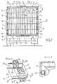
- the drawing illustrates a heavy goods vehicle 1 whose body 2 has a rear opening 3 delimited by a floor 4, a roof 5 and the edge 6 of the lateral sides 7.
- the edges 6, the roof 5 and floor 4 are substantially in the same plane.
- the lateral sides 7 are provided with a profile 8 which they carry so that this profile does not protrude.
- each profile 8 is fixed, for example riveted or welded, to the external face of each lateral side 7 by means of a tab 8a.
- the lateral sides 7 end by a post.
- the tab 8a may be useless, the profile 8 is then only fixed to the outer face of said post.
- Profile 8 internally contains a shaft 9 on which are hinged or knuckled 10 by means of pins 11 (fig. 2) or other equivalent means.
- Fig. 2 shows that the profile 8 has notches 12 at level of the hinges or knuckles 10 to allow their pivoting towards the outside of the box 2 as shown in fig. 3.
- the hinges or knuckles 10 are intended for the articulation of doors 13, 14.
- Each door includes a core 15 held in a frame 16 which comprises upper crosspieces 17, lower 18 and side uprights 19, 20.
- Each lateral upright is constituted by a profile 21 produced by one or more segments (fig. 2), for example in extruded aluminum which delimits a channel 22 and a groove 23 (fig. 4).
- the channel 22 is of polygonal shape corresponding to end pieces 27 and 28 of a connector 24, and the groove 23 is provided to fit the edge of the core 15 by making a tongue and groove assembly, which is well illustrated by figs. 2 and 4.
- the sections 21 forming the crosspieces 17, 18 and the amount 20 of each door are continuous while the profile 21 forming the amount 19 is preferably formed by profile segments 21 1 , 21 2 ... 21 n connected between them by fittings 24 (fig. 5).
- the connections 24 are constituted by molded parts comprising a body 25 fitted into the profiles 21 and extended on one side by lugs 26 defining a groove 23a corresponding to the groove 23 of the profile segments 21 1 , 21 2 ... 21 n .
- the body 25 also has, on its top and bottom, end caps 27, 28, of polygonal section, corresponding exactly to the channel 22 of the profiles.
- Small ribs 29 advantageously protrude from the side walls of the end pieces 27, 28 in order to be forcibly engaged, as illustrated in FIG. 5, in channel 22, profile segments 21 1 ... 21 n .
- the ribs 29 constitute friction elements.
- each fitting has a recess 30 well visible in fig. 5 to contain the hinges or knuckles 10 whose free end is wedged on a shaft 31 parallel to the shaft 9 and crossed by pins 32 (fig. 2).
- the shaft 31 extends through the channel 22 and passes through bores 33, 34 of the ends 27, 28 (fig. 5).
- the profiles 21 constituting the lateral uprights likewise that the connections 24 have grooves 38 for placing in place of pins 39 ensuring the maintenance of deformable joints 40 intended to bear in particular against the edges 6 on the lateral sides of the body 2 as well as against the edge of floor 4 and roof 5. Profiles 21 are described more in detail in the following.
- corner pieces 41 (fig. 7).
- the corner pieces are advantageously made by molding so that their external appearance corresponds to that of deformable joints.
- Each corner piece presents its end a connection end piece 42 engaged in the profile of the corresponding joint to which it is glued. This avoids the risk of cutting tab whose junction can break.
- Fig. 2 illustrates an advantageous embodiment of the core 15 of the doors.
- the core is made from extruded profiles 44 having at one end of the lugs 45 forcibly engaged in the groove 23 of the lateral uprights 19, 20 and at the other end a constricted part 46 forming a false tongue intended to be engaged in a groove 23 1 delimited by the lugs 45 of a profile of the same shape.
- Each extruded section 44 advantageously comprises at least a reinforcing partition 47 and a tubular partition 48 delimiting a bore 49.
- the bore 49 of the tubular partition 48 of at least one profile extruded 44 from each door is used for mounting bars 52 connecting bolts 53, 54 maneuverable from control levers 55 (fig. 1) preferably arranged in below doors to allow locking, respectively unlocking the bolts 53, 54 in strikes 56, 57.
- each door can be pivoted, hinges or knuckles 10 causing the shaft 9 to rotate at an angle which can exceed 180 ° and reach 270 ° so that said doors occupy a position for which they extend parallel to the lateral sides 7 of the body 2 which is illustrated in fig. 3.
- each shaft 9 is arranged inside the 8-channel profile, hinges or knuckles 10 do not protrude in the space left free by the doors, so that any the interior width of the box is available and only goods, loaded or unloaded by elevators and pallets, do not risk striking protruding parts of the internal space of the body 2 or of the parts of the doors. This is clear from the illustration following fig. 3.
- Fig. 3 illustrates in section the seal installed but does not under no tightening stress since the door is in the open position.
- the general shape in section of the joint is approximately that of a trapezoid whose small base 50 is provided with pins 39 which project therefrom.
- the small base 50 and the large base 51 are connected by an oblique partition 60 extending internally from the small base, in the vicinity from pawn level 39 to the most protruding part and rounded 61 of the large base 51.
- the large base is extended by a reinforced flexible lip 62 at its base by the short side 63 of the trapezoid.
- the other short side 64 of the trapezoid is inclined and is extended, on the one hand, by means of a flexible lip 65 of short length and, on the other hand, by means of a nesting heel 66 bearing against the external face of the upright 20 corresponding or a cross as the case may be.
- the joint described above is produced by extrusion of a flexible and elastic material, for example an elastomer.
- the particular configuration described allows a connection waterproof in all circumstances, which is illustrated in different figures which show in full line the parts deformed and in hatched line the non-deformed parts.
- the fig. 2 and 4 show that part of the large base 51 is deformed in the direction for which it results in pivoting of the lip 65 applied against the edge 6.
- the partition 60 acts like an internal spacer preventing tipping from the lip 65 towards the outside of the edge 6.
- the seal 40 is offset towards the inside of the door to work in the manner explained above and reduce the extent of the part that can be wetted by the rain.
- the pressure exerted on the seal 40 when the door is closed also maintains the flexible lip 62 still in support and the deformation undergone increases the pressure exerted by elsewhere by the flexible lip 65.
- Fig. 8 shows that each door leaf is provided on the edges facing each other with seals 40 which bear one on the other from the inside of the doors.
- a joint cover 67 is carried by door 13 and has a deformable part pressing against door 14.
- FIGs. 9 and 10 show torsion springs 68 which are inserted in each channel 22 so that an end strand 68 a is engaged in a slot 31 a of each shaft 31 secured to the hinges or knuckles 10 by the pins 32. L the other end strand 68b of the springs 68 is supported inside the profile forming the channel 22.
- the function of the spring acting on the hinge or knuckle ensure openness priority across the entire hinge to know that the hinges or knuckles 10 remain in the plane of the door to an opening of approximately 180 ° this from which the knuckle abuts on the support. Rotation is then possible up to 270 ° in stressing the spring. This allows deployment is a separation of the seal 40 in good conditions without tearing by friction of a part of it. Stubborn 69 prevents escape of the spring.
Landscapes
- Engineering & Computer Science (AREA)
- Mechanical Engineering (AREA)
- Hinges (AREA)
- Wing Frames And Configurations (AREA)
Claims (10)
- System von angelenkten Türen für Fahrzeuge, Transportbehälter und ähnliche Anwendungen, bei welchem jede Tür (13, 14) durch Angeln oder Scharnieraugen (10) an dem Kasten (2) des Fahrzeuges angelenkt ist und innen mit einer verformbaren Umfangsdichtung (40) versehen ist, dadurch gekennzeichnet, dass die Angeln oder Scharnieraugen (10) durch Wellen (9, 31) getragen werden, die in jeweils mit den seitlichen Seiten (7) des Kastens (2) des Fahrzeuges fluchtend ausgerichteten Profilen (8) angeordnet sind, ohne aus dem Inneren des besagten Kastens (2) hervorzuragen.
- System von angelenkten Türen gemäss Anspruch 1, dadurch gekennzeichnet, dass die Angeln oder Scharnieraugen (10) mit jeder Tür (13, 14) durch eine Welle (31), an welcher sie durch Haltestücke (32) festgesetzt sind, verbunden sind, wobei die besagte Welle innerhalb eines einen Seitenpfosten der besagten Tür (13, 14) bildenden Profils (21) untergebracht ist, wobei das die Angeln oder Scharnieraugen (10) enthaltende besagte Profil (21) durch durch Verbindungsstücke (24) verbundene Profilsegmente (211, 212...21n) gebildet wird, welche Verbindungsstücke in die Profilsegmente (211, 212, ...21n) eingesteckte Ansatzstücke (27, 28) aufweisen, welche Profilsegmente einen Kanal (22) für die besagten Ansatzstücke abgrenzen.
- System von angelenkten Türen gemäss einem der Ansprüche 1 und 2, dadurch gekennzeichnet, dass die Verbindungsstücke (24) aus geformtem Werkstoff hergestellt werden, und jeweils eine Aussparung (30) für jede Angel bzw. jedes Scharnierauge abgrenzen.
- System von angelenkten Türen gemäss einem der Ansprüche 1 bis 3, dadurch gekennzeichnet, dass die die Seitenpfosten (19, 20) jeder Tür bildenden Profile (21) und Profilsegmente (211, 212...21n) sowie die Verbindungsstücke (24) eine Nut (23, 23a) zum Einstecken einer Seele (15) abgrenzende Ansatzlappen aufweisen, welche Seele ebenfalls in einer Nut (23) von eine obere und eine untere Querstrebe (17, 18) bildenden Profilen eingesteckt ist.
- System von angelenkten Türen gemäss einem der Ansprüche 1 bis 4, gekennzeichnet durch mit Ansatzstücken (42) versehene geformte Eckwinkelstücke (41), um die verformbaren Dichtungen (40) durch Einstecken und Verkleben zu verbinden.
- System von angelenkten Türen gemäss einem der Ansprüche 1 bis 5, dadurch gekennzeichnet, dass die die obere und untere Querstrebe (17, 18) sowie die Seitenpfosten (19, 20) bildenden Profile Nuten (38) zur Einführung von Stiften (39) zur Befestigung von verformbaren Dichtungen (40) aufweisen, welche Dichtungen einen etwa trapezförmigen Querschnitt aufweisen, dessen kleine Basis (50) die Stifte (39) aufweist, wobei die kleine Basis (50) und die grosse Basis (51) durch eine etwa von den Stiften (39) ab zu dem vorspringendsten Teil hin der grossen Basis (51) verlaufende schräge Trennwand (60) verbunden sind.
- System von angelenkten Türen gemäss Anspruch 6, dadurch gekennzeichnet, dass die grosse Basis der Dichtung (40) durch eine an ihrer Basis durch den kleinen Schenkel (61) des Trapezes verstärkte nachgiebige Lippe (62) fortgesetzt wird, und dass der andere kleine Schenkel des Trapezes geneigt und durch eine nachgiebige Lippe (65) und mittels einer Einstecknase (66), um sich an der Aussenfläche eines Pfostens (20) jeweils einer Querstrebe (17, 18) abzustützen, fortgesetzt wird.
- System von angelenkten Türen gemäss einem der Ansprüche 1 bis 7, dadurch gekennzeichnet, dass die Seele (15) jeder Tür durch Ineinanderstecken von extrudierten Profilen (44) hergestellt wird, die auf einer Seite eine Nut (231) abgrenzende Ansatzlappen (45) und auf der anderen Seite einen eine in der Nut (231) des nachfolgenden Profils eingesteckte falsche Zunge abgrenzenden verengten Teil (46) aufweisen.
- System von angelenkten Türen gemäss einem der Ansprüche 1 bis 8, dadurch gekennzeichnet, dass die die Seele (15) jeder Tür bildenden extrudierten Profile im Inneren wenigstens eine rohrförmige Trennwand (48) zur Aufnahme von jeweils oberhalb und unterhalb der Tür angeordneten Riegelrasten (53, 54) tragenden Stangen (52) abgrenzen, zur Zusammenwirkung mit Schlossplatten (56, 57).
- System von angelenkten Türen gemäss einem der Ansprüche 1 bis 9, dadurch gekennzeichnet, dass die mit den Angeln bzw. Scharnieraugen (10) durch Haltestifte (32) verbundenen Wellen (31) mit einem Ende einer Feder (68) verbunden sind, dessen andere Ende sich im Anschlag an das Profil (21) befindet, um einen Öffnungsvorrang zu gewährleisten, was ausmacht, dass jede Angel bzw. Scharnieröse in der Ebene der Tür bis zu einer Öffnung von 180° der Tür verbleibt, wobei die Öffnung bis 270° durch Beaufschlagung der Feder stattfindet.
Applications Claiming Priority (2)
| Application Number | Priority Date | Filing Date | Title |
|---|---|---|---|
| FR9502256 | 1995-02-27 | ||
| FR9502256A FR2730957B1 (fr) | 1995-02-27 | 1995-02-27 | Systeme de portes articulees pour vehicules, conteneurs et applications analogues |
Publications (2)
| Publication Number | Publication Date |
|---|---|
| EP0728608A1 EP0728608A1 (de) | 1996-08-28 |
| EP0728608B1 true EP0728608B1 (de) | 1999-03-24 |
Family
ID=9476532
Family Applications (1)
| Application Number | Title | Priority Date | Filing Date |
|---|---|---|---|
| EP19960400405 Expired - Lifetime EP0728608B1 (de) | 1995-02-27 | 1996-02-26 | Gelenktürsystem für Fahrzeuge, Behälter und ähnliche Verwendungen |
Country Status (4)
| Country | Link |
|---|---|
| EP (1) | EP0728608B1 (de) |
| DE (2) | DE29602837U1 (de) |
| ES (1) | ES2130758T3 (de) |
| FR (1) | FR2730957B1 (de) |
Families Citing this family (4)
| Publication number | Priority date | Publication date | Assignee | Title |
|---|---|---|---|---|
| FR2806121B1 (fr) | 2000-03-13 | 2002-11-15 | Libner Sa | Dispositif de porte articulees pour vehicules, conteneurs ou similaires |
| FR2835560B1 (fr) * | 2002-02-05 | 2004-10-01 | Pommier S A | Agencement de charniere pour monter pivotant un ouvrant sur une structure fixe |
| ITMI20040667A1 (it) * | 2004-04-02 | 2004-07-02 | Autocar S P A | Anta di porta del vano di carico di un veicolo da trasporto e kit di fornitura dell'anta |
| AT520893B1 (de) * | 2018-01-17 | 2021-07-15 | Amari Austria Gmbh | Tür für Fahrzeugaufbauten |
Family Cites Families (3)
| Publication number | Priority date | Publication date | Assignee | Title |
|---|---|---|---|---|
| FR1548311A (de) * | 1967-06-05 | 1968-12-06 | ||
| FR2614851A1 (fr) * | 1987-05-07 | 1988-11-10 | Lamberet Vehicules Frigorifiqu | Perfectionnement aux cellules destinees au transport et au stockage de marchandises |
| DE9110532U1 (de) * | 1990-09-25 | 1991-10-10 | Helmut Weisbender Gmbh & Co Kg, 5430 Montabaur, De |
-
1995
- 1995-02-27 FR FR9502256A patent/FR2730957B1/fr not_active Expired - Fee Related
-
1996
- 1996-02-17 DE DE1996202837 patent/DE29602837U1/de not_active Expired - Lifetime
- 1996-02-26 DE DE1996601820 patent/DE69601820T2/de not_active Expired - Lifetime
- 1996-02-26 EP EP19960400405 patent/EP0728608B1/de not_active Expired - Lifetime
- 1996-02-26 ES ES96400405T patent/ES2130758T3/es not_active Expired - Lifetime
Also Published As
| Publication number | Publication date |
|---|---|
| ES2130758T3 (es) | 1999-07-01 |
| DE29602837U1 (de) | 1996-04-11 |
| DE69601820D1 (de) | 1999-04-29 |
| EP0728608A1 (de) | 1996-08-28 |
| FR2730957A1 (fr) | 1996-08-30 |
| DE69601820T2 (de) | 1999-09-16 |
| FR2730957B1 (fr) | 1997-04-30 |
Similar Documents
| Publication | Publication Date | Title |
|---|---|---|
| EP0464878B1 (de) | Gelenkwerk für Platten und Anwendung auf Sektionaltore | |
| FR2748868A1 (fr) | Boitier etanche de raccordement de cables | |
| FR2711454A1 (fr) | Liaison d'angle pour armoire, et armoire électrique comportant de telles liaisons. | |
| FR2855861A1 (fr) | Produit articule particulierement approprie pour la fixation de barres a l'interieur de mecanisme de porte pour automobile | |
| EP2039593A1 (de) | Karosseriestruktur eines Kraftfahrzeugs mit verstärker Verbindung zwischen vorderem Querträger des Fahrzeugdachs und Futter des Ständers für die Windschutzscheibe | |
| EP0728608B1 (de) | Gelenktürsystem für Fahrzeuge, Behälter und ähnliche Verwendungen | |
| EP0002994B1 (de) | Metalleiter | |
| FR2928633A1 (fr) | Benne pour le transport et/ou le stockage de charge(s) | |
| CA2200677C (fr) | Systeme d'assemblage de panneaux prefabriques pour la realisation d'une cloison de piscine et cloison de piscine ainsi obtenue | |
| EP1140535A1 (de) | Sicherheitsvorrichtung mit glasöffnung mit beweglichem verschluss | |
| EP0038229A1 (de) | Scharnier zum Verbinden zweier Paneele, insbesondere zum Verbinden eines drehbaren Paneels mit einem feststehenden Paneel | |
| LU82577A1 (fr) | Charniere a ouverture limitee pour portes ou portieres | |
| EP0651122B1 (de) | Verbesserung an Scharnieren zur gelenkigen Verbindung eines Flügels an einem Rahmen | |
| FR2765617A1 (fr) | Dispositif d'articulation notamment pour planches et rideau mouvant forme de planches assemblees au moyen de tels dispositifs | |
| FR3097892A1 (fr) | Capot de recouvrement pour un entraînement de porte ou de fenêtre | |
| EP1306498A1 (de) | Befestigungseinrichtung für Platten, insbesondere für Verandadachplatten und Veranda mit einer solcher Einrichtung | |
| FR2924996A1 (fr) | Benne, de preference amovible, pour le stockage et le transport de charge | |
| FR2738582A1 (fr) | Bras de deploiement pour store et ensemble formant store | |
| EP1709259A1 (de) | Klappbare stufenvorrichtung wie eine treppe oder leiter | |
| FR2729985A1 (fr) | Structure d'installation generale a mise en place de panneaux de cloison facilitee | |
| FR2696138A1 (fr) | Bras d'essuie-glace à carter moulé, notamment pour véhicule automobile. | |
| EP0225268B1 (de) | Ladevorrichtung für Müllsammelbehälter auf Müllfahrzeugen | |
| FR2636921A1 (fr) | Conteneur | |
| FR2987860A1 (fr) | Abri pour bassin de piscine | |
| FR2918401A1 (fr) | Abri pour piscine |
Legal Events
| Date | Code | Title | Description |
|---|---|---|---|
| PUAI | Public reference made under article 153(3) epc to a published international application that has entered the european phase |
Free format text: ORIGINAL CODE: 0009012 |
|
| AK | Designated contracting states |
Kind code of ref document: A1 Designated state(s): BE DE ES FR GB IT NL |
|
| 17P | Request for examination filed |
Effective date: 19961111 |
|
| GRAG | Despatch of communication of intention to grant |
Free format text: ORIGINAL CODE: EPIDOS AGRA |
|
| 17Q | First examination report despatched |
Effective date: 19980525 |
|
| GRAG | Despatch of communication of intention to grant |
Free format text: ORIGINAL CODE: EPIDOS AGRA |
|
| GRAG | Despatch of communication of intention to grant |
Free format text: ORIGINAL CODE: EPIDOS AGRA |
|
| GRAH | Despatch of communication of intention to grant a patent |
Free format text: ORIGINAL CODE: EPIDOS IGRA |
|
| GRAH | Despatch of communication of intention to grant a patent |
Free format text: ORIGINAL CODE: EPIDOS IGRA |
|
| GRAA | (expected) grant |
Free format text: ORIGINAL CODE: 0009210 |
|
| AK | Designated contracting states |
Kind code of ref document: B1 Designated state(s): BE DE ES FR GB IT NL |
|
| REF | Corresponds to: |
Ref document number: 69601820 Country of ref document: DE Date of ref document: 19990429 |
|
| GBT | Gb: translation of ep patent filed (gb section 77(6)(a)/1977) |
Effective date: 19990604 |
|
| REG | Reference to a national code |
Ref country code: ES Ref legal event code: FG2A Ref document number: 2130758 Country of ref document: ES Kind code of ref document: T3 |
|
| PLBE | No opposition filed within time limit |
Free format text: ORIGINAL CODE: 0009261 |
|
| STAA | Information on the status of an ep patent application or granted ep patent |
Free format text: STATUS: NO OPPOSITION FILED WITHIN TIME LIMIT |
|
| 26N | No opposition filed | ||
| REG | Reference to a national code |
Ref country code: GB Ref legal event code: IF02 |
|
| PGFP | Annual fee paid to national office [announced via postgrant information from national office to epo] |
Ref country code: NL Payment date: 20070227 Year of fee payment: 12 |
|
| PGFP | Annual fee paid to national office [announced via postgrant information from national office to epo] |
Ref country code: BE Payment date: 20070307 Year of fee payment: 12 |
|
| BERE | Be: lapsed |
Owner name: *POMMIER & CIE Effective date: 20080228 |
|
| NLV4 | Nl: lapsed or anulled due to non-payment of the annual fee |
Effective date: 20080901 |
|
| PG25 | Lapsed in a contracting state [announced via postgrant information from national office to epo] |
Ref country code: NL Free format text: LAPSE BECAUSE OF NON-PAYMENT OF DUE FEES Effective date: 20080901 |
|
| PG25 | Lapsed in a contracting state [announced via postgrant information from national office to epo] |
Ref country code: BE Free format text: LAPSE BECAUSE OF NON-PAYMENT OF DUE FEES Effective date: 20080228 |
|
| PGFP | Annual fee paid to national office [announced via postgrant information from national office to epo] |
Ref country code: IT Payment date: 20100301 Year of fee payment: 15 |
|
| PGFP | Annual fee paid to national office [announced via postgrant information from national office to epo] |
Ref country code: GB Payment date: 20100301 Year of fee payment: 15 |
|
| PGFP | Annual fee paid to national office [announced via postgrant information from national office to epo] |
Ref country code: ES Payment date: 20100326 Year of fee payment: 15 |
|
| GBPC | Gb: european patent ceased through non-payment of renewal fee |
Effective date: 20110226 |
|
| PG25 | Lapsed in a contracting state [announced via postgrant information from national office to epo] |
Ref country code: IT Free format text: LAPSE BECAUSE OF NON-PAYMENT OF DUE FEES Effective date: 20110226 |
|
| PG25 | Lapsed in a contracting state [announced via postgrant information from national office to epo] |
Ref country code: GB Free format text: LAPSE BECAUSE OF NON-PAYMENT OF DUE FEES Effective date: 20110226 |
|
| REG | Reference to a national code |
Ref country code: ES Ref legal event code: FD2A Effective date: 20120411 |
|
| PG25 | Lapsed in a contracting state [announced via postgrant information from national office to epo] |
Ref country code: ES Free format text: LAPSE BECAUSE OF NON-PAYMENT OF DUE FEES Effective date: 20110227 |
|
| PGFP | Annual fee paid to national office [announced via postgrant information from national office to epo] |
Ref country code: DE Payment date: 20140430 Year of fee payment: 19 |
|
| REG | Reference to a national code |
Ref country code: FR Ref legal event code: PLFP Year of fee payment: 20 |
|
| PGFP | Annual fee paid to national office [announced via postgrant information from national office to epo] |
Ref country code: FR Payment date: 20150225 Year of fee payment: 20 |
|
| REG | Reference to a national code |
Ref country code: DE Ref legal event code: R119 Ref document number: 69601820 Country of ref document: DE |
|
| PG25 | Lapsed in a contracting state [announced via postgrant information from national office to epo] |
Ref country code: DE Free format text: LAPSE BECAUSE OF NON-PAYMENT OF DUE FEES Effective date: 20150901 |