EP0728359B1 - Flash-eprom-integrierte schaltungsarchitektur - Google Patents
Flash-eprom-integrierte schaltungsarchitektur Download PDFInfo
- Publication number
- EP0728359B1 EP0728359B1 EP94928111A EP94928111A EP0728359B1 EP 0728359 B1 EP0728359 B1 EP 0728359B1 EP 94928111 A EP94928111 A EP 94928111A EP 94928111 A EP94928111 A EP 94928111A EP 0728359 B1 EP0728359 B1 EP 0728359B1
- Authority
- EP
- European Patent Office
- Prior art keywords
- flash eprom
- columns
- bit lines
- over
- coupled
- Prior art date
- Legal status (The legal status is an assumption and is not a legal conclusion. Google has not performed a legal analysis and makes no representation as to the accuracy of the status listed.)
- Expired - Lifetime
Links
- 238000009792 diffusion process Methods 0.000 claims description 186
- 238000007667 floating Methods 0.000 claims description 98
- 229910052751 metal Inorganic materials 0.000 claims description 52
- 239000002184 metal Substances 0.000 claims description 52
- 230000015654 memory Effects 0.000 claims description 51
- 239000000758 substrate Substances 0.000 claims description 41
- 239000004020 conductor Substances 0.000 claims description 19
- 239000004065 semiconductor Substances 0.000 claims description 12
- 238000002955 isolation Methods 0.000 claims description 11
- 229910021420 polycrystalline silicon Inorganic materials 0.000 claims description 10
- 229920005591 polysilicon Polymers 0.000 claims description 10
- 210000004027 cell Anatomy 0.000 description 165
- 238000000034 method Methods 0.000 description 23
- 230000008569 process Effects 0.000 description 20
- 238000000151 deposition Methods 0.000 description 18
- 230000008021 deposition Effects 0.000 description 16
- 238000005516 engineering process Methods 0.000 description 12
- 150000004767 nitrides Chemical class 0.000 description 11
- 239000002019 doping agent Substances 0.000 description 10
- 230000008878 coupling Effects 0.000 description 9
- 238000010168 coupling process Methods 0.000 description 9
- 238000005859 coupling reaction Methods 0.000 description 9
- 238000013461 design Methods 0.000 description 9
- 239000007943 implant Substances 0.000 description 9
- 238000004519 manufacturing process Methods 0.000 description 9
- 239000011295 pitch Substances 0.000 description 9
- 238000012360 testing method Methods 0.000 description 6
- 238000010586 diagram Methods 0.000 description 5
- 238000007599 discharging Methods 0.000 description 5
- 230000007246 mechanism Effects 0.000 description 5
- 125000006850 spacer group Chemical group 0.000 description 4
- WQJQOUPTWCFRMM-UHFFFAOYSA-N tungsten disilicide Chemical compound [Si]#[W]#[Si] WQJQOUPTWCFRMM-UHFFFAOYSA-N 0.000 description 4
- 229910021342 tungsten silicide Inorganic materials 0.000 description 4
- 230000005689 Fowler Nordheim tunneling Effects 0.000 description 3
- 238000013459 approach Methods 0.000 description 3
- 210000000352 storage cell Anatomy 0.000 description 3
- 230000005641 tunneling Effects 0.000 description 3
- 238000003491 array Methods 0.000 description 2
- 230000015572 biosynthetic process Effects 0.000 description 2
- 238000005530 etching Methods 0.000 description 2
- 230000006870 function Effects 0.000 description 2
- 239000011810 insulating material Substances 0.000 description 2
- 239000012212 insulator Substances 0.000 description 2
- 230000000873 masking effect Effects 0.000 description 2
- 238000012552 review Methods 0.000 description 2
- XUIMIQQOPSSXEZ-UHFFFAOYSA-N Silicon Chemical compound [Si] XUIMIQQOPSSXEZ-UHFFFAOYSA-N 0.000 description 1
- 229910021417 amorphous silicon Inorganic materials 0.000 description 1
- 238000000137 annealing Methods 0.000 description 1
- 230000009286 beneficial effect Effects 0.000 description 1
- 239000002131 composite material Substances 0.000 description 1
- 238000012937 correction Methods 0.000 description 1
- 230000002950 deficient Effects 0.000 description 1
- 238000005137 deposition process Methods 0.000 description 1
- 230000006866 deterioration Effects 0.000 description 1
- 230000000694 effects Effects 0.000 description 1
- 238000002347 injection Methods 0.000 description 1
- 239000007924 injection Substances 0.000 description 1
- 238000011068 loading method Methods 0.000 description 1
- 238000001465 metallisation Methods 0.000 description 1
- 238000012986 modification Methods 0.000 description 1
- 230000004048 modification Effects 0.000 description 1
- 230000003647 oxidation Effects 0.000 description 1
- 238000007254 oxidation reaction Methods 0.000 description 1
- 238000012856 packing Methods 0.000 description 1
- 238000002161 passivation Methods 0.000 description 1
- 230000002093 peripheral effect Effects 0.000 description 1
- 229920002120 photoresistant polymer Polymers 0.000 description 1
- 238000001020 plasma etching Methods 0.000 description 1
- 230000009467 reduction Effects 0.000 description 1
- 230000004044 response Effects 0.000 description 1
- 230000011664 signaling Effects 0.000 description 1
- 229910052710 silicon Inorganic materials 0.000 description 1
- 239000010703 silicon Substances 0.000 description 1
- 238000003860 storage Methods 0.000 description 1
- 230000008719 thickening Effects 0.000 description 1
Images









Classifications
-
- G—PHYSICS
- G11—INFORMATION STORAGE
- G11C—STATIC STORES
- G11C8/00—Arrangements for selecting an address in a digital store
- G11C8/12—Group selection circuits, e.g. for memory block selection, chip selection, array selection
-
- G—PHYSICS
- G08—SIGNALLING
- G08G—TRAFFIC CONTROL SYSTEMS
- G08G1/00—Traffic control systems for road vehicles
- G08G1/01—Detecting movement of traffic to be counted or controlled
- G08G1/017—Detecting movement of traffic to be counted or controlled identifying vehicles
-
- G—PHYSICS
- G11—INFORMATION STORAGE
- G11C—STATIC STORES
- G11C16/00—Erasable programmable read-only memories
- G11C16/02—Erasable programmable read-only memories electrically programmable
- G11C16/04—Erasable programmable read-only memories electrically programmable using variable threshold transistors, e.g. FAMOS
- G11C16/0491—Virtual ground arrays
-
- G—PHYSICS
- G11—INFORMATION STORAGE
- G11C—STATIC STORES
- G11C16/00—Erasable programmable read-only memories
- G11C16/02—Erasable programmable read-only memories electrically programmable
- G11C16/06—Auxiliary circuits, e.g. for writing into memory
- G11C16/10—Programming or data input circuits
-
- G—PHYSICS
- G11—INFORMATION STORAGE
- G11C—STATIC STORES
- G11C16/00—Erasable programmable read-only memories
- G11C16/02—Erasable programmable read-only memories electrically programmable
- G11C16/06—Auxiliary circuits, e.g. for writing into memory
- G11C16/10—Programming or data input circuits
- G11C16/14—Circuits for erasing electrically, e.g. erase voltage switching circuits
- G11C16/16—Circuits for erasing electrically, e.g. erase voltage switching circuits for erasing blocks, e.g. arrays, words, groups
-
- H—ELECTRICITY
- H10—SEMICONDUCTOR DEVICES; ELECTRIC SOLID-STATE DEVICES NOT OTHERWISE PROVIDED FOR
- H10B—ELECTRONIC MEMORY DEVICES
- H10B41/00—Electrically erasable-and-programmable ROM [EEPROM] devices comprising floating gates
- H10B41/30—Electrically erasable-and-programmable ROM [EEPROM] devices comprising floating gates characterised by the memory core region
-
- H—ELECTRICITY
- H10—SEMICONDUCTOR DEVICES; ELECTRIC SOLID-STATE DEVICES NOT OTHERWISE PROVIDED FOR
- H10B—ELECTRONIC MEMORY DEVICES
- H10B69/00—Erasable-and-programmable ROM [EPROM] devices not provided for in groups H10B41/00 - H10B63/00, e.g. ultraviolet erasable-and-programmable ROM [UVEPROM] devices
Definitions
- the present invention relates to flash EPROM memory technology, and more particularly to an improved flash EPROM memory architecture and data cell structure.
- Flash EPROMs are a growing class of non-volatile storage integrated circuits. These flash EPROMs have the capability of electrically erasing, programming, and reading a memory cell in the chip.
- the memory cell in a flash EPROM is formed using so-called floating gate transistors in which the data is stored in a cell by charging or discharging the floating gate.
- the floating gate is a conductive material, typically made of polysilicon, which is insulated from the channel of the transistor by a thin layer of oxide, or other insulating material, and insulated from the control gate or word line of the transistor by a second layer of insulating material.
- the floating gate is discharged to establish the opposite memory state. This function is typically carried out by F-N tunneling mechanism between the floating gate and the source or the drain of the transistor, or between the floating gate and the substrate. For instance, the floating gate may be discharged through the source by establishing a large positive voltage from the source to the gate, while the drain is left at a floating potential.
- contactless arrays include an array of storage cells which are coupled to one another by buried diffusion, and the buried diffusion is only-periodically coupled through contacts to a metal bit line.
- Earlier flash EPROM designs such as the Mukherjee, et al., system required a "half' metal contact for each memory cell. Because metal contacts use a significant area on an integrated circuit, they are a major impediment to creating a high density memory technology. Furthermore, as the device becomes smaller and smaller, the area reduction becomes limited by the metal over contact pitches of adjacent drain and source bit lines used to access the storage cells in the array.
- EP-A-0,552,531 describes a contactless flash EPROM cell and array design based on a drain-source-drain configuration, in which a single source diffusion is shared by two columns of transistors.
- US 5,345,416 relates to an EPROM architecture, in which a plurality of sub-bit lines and sub-column lines are provided which are biased in combination to select individual cells to be accessed.
- the separate sub-column lines are selectively coupled to one of a number of discrete main column lines and are parallel to the columns of flash EPROM cells, and the main bit lines.
- the present invention provides a flash EPROM integrated circuit module as defined by Claim 1.
- a novel contactless flash EPROM cell is provided which is preferably based on a unique drain-source-drain configuration, in which a single source diffusion is shared by two columns of transistors. Such an approach results in a dense, segmentable flash EPROM chip.
- a flash EPROM integrated circuit module on a semiconductor substrate comprising: a memory array including at least M rows and at least 2N columns of flash EPROM cells; M word lines, each word line being coupled to the flash EPROM cells in a corresponding one of the M rows of flash EPROM cells; a plurality of global bit lines; a reference conductor orthogonal to the global bit lines; data in and out circuitry coupled to the plurality of global bit lines which provide for reading and writing data in the memory array; wherein the 2N columns of flash EPROM cells in the memory array comprise: N pairs of columns of flash EPROM cells, each pair of columns comprising a plurality of segments, each segment in the plurality comprising: a first and a second local bit line; a local source line coupled to the reference conductor; a first set of flash EPROM cells in a first column of the pair of columns connected to the first local bit line, a second set of flash EPROM cells in a second column of the pair of columns connected to the second
- the structure can be extended to provide for sharing one metal bit line among more than 2 columns of cells.
- the memory array comprises a flash EPROM transistor array in which an elongated first drain diffusion region, an elongated source diffusion region, and an elongated second drain diffusion region, are formed in a semiconductor substrate along essentially parallel lines. Field oxide regions are grown on opposite sides of the first and second drain diffusion regions. Floating gates and control gate word lines are formed orthogonal to the drain-source-drain structure to establish two columns of storage cells having a shared source region. The shared source region is coupled to a virtual ground terminal. The drain diffusion regions are coupled through select transistors to global bit lines.
- the cell structure according to one aspect of the invention uses one metal global bit line which extends essentially parallel to the drain, source and drain diffusion regions for two columns of cells, and a virtual ground supply which coupled a plurality of columns of transistors to a virtual ground terminal through a horizontal conductor, such as a buried diffusion line.
- a horizontal conductor such as a buried diffusion line.
- the memory array includes a plurality of segments of drain-source-drain structures, as described above.
- the selector circuitry includes segment selector circuitry, coupled to two local bit lines provided by the drain diffusion regions in the segment.
- the segment selector circuitry provides for selective connection of the first and second columns of cells within a given segment to one of the N bit lines.
- the selector circuitry includes a first transistor having a first terminal in the first drain diffusion region of the structure, and a second terminal coupled to a contact to one of the N global bit lines.
- the second transistor has a first terminal coupled to the second drain diffusion region of the structure and a second terminal coupled to the contact.
- the first and second transistors are independently controlled by left and right select lines which are parallel to the word lines.
- the semiconductor substrate has a first conductivity type, a first well in the substrate of a second conductivity type, and a second well of the first conductivity type in the first well.
- the flash EPROM cells are made in the second well to allow application of a negative potential to at least one of the source and drain during an operation to charge the floating gate in the cells. This substantially reduces the magnitude of the high positive voltage which must be applied to the gate to induce F-N tunneling for cells to be charged.
- the array also uses a negative potential on the gate of cells to be discharged. This substantially reduces the magnitude of the potential which must be applied to the drain to induce F-N tunneling to discharge the cell.
- the lower magnitude voltages used substantially relax the specifications for the integrated circuit components which handle the program and erase voltages, making the device more economical and easier to manufacture. At the same time, the endurance of the memory is improved by reducing hot hole generation during program mode.
- the array is configured so that the "erased” condition corresponds to a charged floating gate, so that the erased cell is non-conducting when addressed, and the "programmed” condition results from discharging the cell, so that the programmed cell is conducting when addressed. This allows an erase operation to occur without pre-programming.
- the array includes redundant rows of flash EPROM cells.
- the redundant rows are used to replace a row in the main array which is addressed with a single word line or set of word lines coupled to a single driver. Because of the discharged condition corresponding to a programmed state, and the use of the negative potentials for programming and erasing, as outlined above, the row redundancy is enabled.
- Prior art flash EPROM cells could not use row redundancy because of the disturbance caused by the failed row in the main array. In particular, because the failed row could not be isolated from the program and/or erased potentials in the main array, the cells in the failed row would progress to an overerase condition, contributing to leakage current on the array, and eventually causing failure of columns.
- a flash EPROM integrated circuit module of preferred embodiments can be made using a two well process, in which the semiconductor substrate has the first conductivity type in the semiconductor substrate, a first well of a second conductivity type in the substrate, and a second well of the first conductivity type in the first well.
- An array of flash EPROM cells is formed in the second well when the array includes 2N columns of flash EPROM cells and M rows.
- the 2N columns of flash EPROM cells comprise N pairs of columns of flash EPROM cells, each pair of columns includes a plurality of segments.
- Each segment in the plurality comprises a first drain diffusion region elongated in a first direction in the second well, a source diffusion region elongated in the first direction in the second well and spaced away from the first drain diffusion region, and a second drain diffusion region elongated in the first direction in the second well and spaced away from the source diffusion region.
- a first insulating layer is placed over the substrate, over the first and second channel regions formed between the drain-source-drain structures, and over the source and drain diffusion regions.
- Floating gate electrodes are applied over the first insulating layer for the two columns of cells in the segment.
- the second insulating layer is placed over the floating gate electrodes. This results in each segment including a first set of flash EPROM cells in a first one of a pair of columns, and a second set of flash EPROM cells in a second one of the pair of columns.
- each coupled to the flash EPROM cells in the one of the M rows of flash EPROM cells are included.
- members of a subset of the M word lines are each coupled to a flash EPROM cell in the first set in a given segment, and a flash EPROM cell in the second set in a given segment.
- each word line intersects two cells in each pair of columns within a given segment.
- the array includes N global bit lines.
- Data in and out circuitry is coupled to the N global bit lines to provide for reading and writing data (using a program and/or erase sequence) in the 2N columns of flash EPROM cells.
- Selector circuitry is coupled to the first and second drain diffusions in each of the plurality of segments, which provides connection of the 2N columns of flash EPROM cells to the N global bit lines.
- the selector circuitry provides for selective connection of two columns of the 2N columns to each of the N global bit lines, so that access to the 2N columns of flash EPROM cells by the data in and out circuitry is provided across the N global bit lines.
- a unique array architecture may be provided with a virtual ground configuration to achieve a high packing density.
- the basic unit of the memory array includes segments of two columns of cells in a drain-source-drain configuration.
- the resulting array structure gives less program and erase disturbance problems to the neighboring unselected bit lines. It also reduces the complexity of the Y decoder design as compared to an array structure which is configured as a source-drain-source-drain array.
- two cells may share one metal pitch, which can further relax metal pitch design rules.
- Decoding for the two columns of cells which are coupled to a given metal line is provided through left and right select transistors coupled to each drain-source-drain segment.
- the unique left and right select transistors are each coupled to a set of rows of word lines as much as 64 high, to improve the reading speed and alleviate program disturbance concerns.
- the array of preferred embodiments has been designed to provide for a conducting state for programmed cells, using negative word line voltages during page program operations. Also, during an erase operation, which has been configured to establish a non-conducting state for the cell, negative drain, source and substrate voltages are applied. Again, this reduces the disturbance problems and the magnitude of positive voltage needed to be applied during the operations. Finally, the array provides for redundant row and redundant column replacement configurations unavailable in prior art designs.
- Fig. 1 provides an overview of the layout of a flash EPROM integrated circuit module according to the present invention.
- the integrated circuit module of Fig. 1 includes a flash EPROM memory array 100 coupled to a plurality of redundant memory cells 101 used for replacing failed cells in the main array as known in the art.
- a plurality of reference cells 102 are used with sense amps 107 for differential sensing the state of the cells in the memory array.
- the sense amps 107 and the program data in structures 103 provide data in and out circuitry coupled to the memory array.
- the flash EPROM integrated circuit typically is operated in a read only mode, a program mode, and an erase mode.
- mode control circuitry 106 is coupled to the array 100.
- a negative potential is applied to either the gate or source and drain of the memory cells.
- a negative voltage generator 108 and a positive voltage generator 109 are used for supplying various reference voltages to the array.
- the negative voltage generator 108 and positive voltage generator 109 are driven by the power supply voltage V cc .
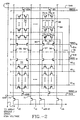
- Fig. 2 illustrates two segments within a larger integrated circuit.
- the segments are divided generally along dotted line 50 and include segment 51A generally above the dotted line 50 and segment 51B generally below the dotted line 50.
- a first pair 52 of columns in segment 51A is laid out in a mirror image with a second pair 53 of columns in segment 51B along a given global bit line pair (e.g., bit lines 70, 71).
- bit lines 70, 71 bit lines 70, 71.
- the memory segments are flipped so as to share virtual ground conductors 54A, 54B (buried diffusion) and metal-to-diffusion contacts 55, 56, 57, 58.
- the virtual ground conductors 54A, 54B extend horizontally across the array to a vertical virtual ground metal line 59 through metal-to-diffusion contacts 60A, 60B.
- the segments repeat on opposite sides of the metal virtual ground line 59 so that adjacent segments share a metal virtual ground line 59.
- the segment layout of Fig. 2 requires two metal contact pitches per column of two transistor cells for the global bit lines and one metal contact pitch per segment for the metal virtual ground line 59.
- Each of the pairs of columns (e.g., 52, 53) along a given bit line pair comprises a set of EPROM cells.
- cells 75-1, 75-2, 75-N comprise a first set of flash EPROM cells in a first one of the pair 77 of columns.
- Cells 76-1, 76-2, 76-N comprise a second set of flash EPROM cells in the second column in the pair 77 of columns.
- the first set of cells and the second set of cells share a common buried diffusion source line 78.
- the cells 75-1, 75-2, 75-N are coupled to buried diffusion drain line 79.
- Cells 76-1, 76-2, 76-N are coupled to buried diffusion drain line 80.
- Selector circuitry comprising top select transistor 81 and top select transistor 82 couple the respective drain diffusion lines 79, 80 to metal global bit lines 83 and 84, respectively.
- the transistor 81 has a source coupled to the drain diffusion line 79 and a drain coupled to a metal contact 57.
- Transistor 82 has a source coupled to the drain diffusion line 80 and a drain coupled to the metal contact 58.
- the gates of transistors 81 and 82 are controlled by the signal TBSEL A to couple the respective columns of flash EPROM cells to the global bit lines 83 and 84.
- the source diffusion line 78 is coupled to the drain of select transistor 85.
- the source of select transistor 85 is coupled to a virtual ground diffusion line 54A.
- the gate of transistor 85A is controlled by the signal BBSEL A .
- a sector of two or more segments as illustrated in Fig. 2 may share word line signals because of the additional decoding provided by the top and bottom block select signals TBSEL A , TBSEL B , BBSEL A , and BBSEL B .
- eight segments share word line drivers, providing a sector eight segments deep.
- the architecture according to Figure 2 provides a sectored flash EPROM array. This is beneficial because the source and drain of transistors in non-selected segments during a read, program or erase cycle may be isolated from the currents and voltages on the bit lines and virtual ground lines. Thus, during a read operation, sensing is improved because leakage current from segments not selected does not contribute to current on the bit lines. During the program and erase operations, the voltages of the virtual ground line, and the bit lines, are isolated from the unselected segments. This allows a sectored erase operation, either segment by segment or preferably sector by sector when the segments within a given sector share word line drivers.
- the bottom block select transistors may not be necessary in an embodiment of the present invention as shown in Fig. 3 below. Also, these block select transistors may share a bottom block select signal with an adjacent segment. Alternatively, the bottom block select transistors (e.g., 65A, 65B) may be replaced by single isolation transistors adjacent the virtual ground terminals 60A, 60B.
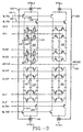
- Fig. 3 illustrates an architecture of the flash EPROM array according to an embodiment of the present invention, in which two columns of flash EPROM cells share a single metal bit line.
- Fig. 3 shows four pairs of columns of the array, where each pair of columns includes flash EPROM cells in a drain-source-drain configuration.
- the first pair 120 of columns includes a first drain diffusion line 121, a source diffusion line 122, and a second drain diffusion line 123.
- Word lines WL0 through WL63 each overlay the floating gates of a cell in a first one of the pairs of columns and a cell in the second one of the pairs of columns.
- a first pair 120 of columns includes one column including cell 124, cell 125, cell 126, and cell 127. Not shown are cells coupled to word lines WL2 through WL61.
- the second one of the pair 120 of columns includes cell 128, cell 129, cell 130, and cell 131.
- a second pair 135 of columns is shown. It has a similar architecture to the pair 120 of columns except that it is laid out in a mirror image.
- the transistor in the first one of the pair of columns such as the cell 125, includes a drain in drain diffusion line 121, and a source in the source diffusion line 122.
- a floating gate overlays the channel region between the first drain diffusion line 121 and the source diffusion line 122.
- the word line WL1 overlays the floating gate of the cell 125 to establish a flash EPROM cell.
- the column pair 120 and column pair 135 share an array virtual ground diffusion 136 (ARVSS).
- ARVSS array virtual ground diffusion 136
- the source diffusion line 122 of column pair 120 is coupled to the ground diffusion 136.
- the source diffusion line 137 of column pair 135 is coupled to the ground diffusion 136.
- each pair 120 of columns of cells shares a single metal line.
- a block right select transistor 138 and a block left select transistor 139 are included.
- the transistor 139 includes a drain in the drain diffusion line 121, a source coupled to a metal contact 140, and a gate coupled to the control signal BLTR1 on line 141.
- the right select transistor 138 includes a source in the drain diffusion line 123, a drain coupled to the metal contact 140, and a gate coupled to the control signal BLTR0 on line 142.
- the select circuitry including transistors 138 and 139, provides for selective connection of the first drain diffusion line 121 and a second drain diffusion line 123 to the metal line 143 (MTBL0) through metal contact 140.
- column pair 135 includes left select transistor 144 and right select transistor 145 which are similarly connected to a metal contact 146.
- Contact 146 is coupled to the same metal line 143 as is contact 140 which is coupled to column pair 120.
- the metal line can be shared by more than two columns of cells with additional select circuitry.
- the architecture shown in Fig. 2 and 3 is based upon a drain-source-drain unit forming two columns of cells which are isolated from adjacent drain-source-drain units to prevent leakage current from adjacent columns of cells.
- the architecture can be extended to units of more than two columns, with appropriate tolerances for leakage current in the sensing circuitry, or other controls on current leakage from unselected cells.
- fourth and fifth diffusion lines could be added within a given isolated region to create a drain-source-drain-source-drain structure which provides four columns of cells.
- the array may be repeated horizontally and vertically as required to establish a large scale flash EPROM memory array.
- column pairs 120 and 150 which share a word line are repeated horizontally to provide a segment of the array. Segments are repeated vertically.
- a group of segments e.g., eight segments having respective word lines coupled to a shared word line driver may be considered a sector of the array.
- word line WL63' may share a word line driver with word line WL63.
- eight word lines share a single word line driver.
- the additional decoding provided by the left and right select transistors (139, 138 for segment 120) allows the shared word line configuration.
- the shared word line configuration has the disadvantage that during a sector erase operation, eight rows of cells all receive the same word line voltage, causing a word line disturbance in cells that are not desired to be erased.
- this disturbance problem can be eliminated by insuring that all sector erase operations decode for segments including all rows of cells coupled to the shared word line drivers. For eight word lines sharing a single driver, a minimum sector erase of eight segments may be desired.
- Fig. 4 is a schematic block diagram of a flash EPROM array meant to illustrate certain features of the present invention.
- the flash EPROM memory module shown in Fig. 4 includes a main flash EPROM array, including sectors 170-1, 170-2, 170-3, 170-N, each sector including eight segments (e.g., SEG0-SEG7).
- a plurality of sets of shared word line drivers 171-1, 171-2, 171-3, 171-N are used to drive the shared word lines of the eight segments in the respective sectors.
- shared word line drivers 171-1 there are 64 shared drivers for sector 170-1. Each of the 64 drivers supplies an output on line 172. Each of these outputs is used to drive eight word lines in respective segments of the sector 170-1 as schematically illustrated in the figure by the division into eight sets of 64 lines.
- block select drivers 173-1, 173-2, 173-3, 173-N are also coupled to the array.
- the block select drivers each drive a left and right block select signal for each segment.
- the segments are implemented as shown in Fig. 3, there is a BLTR1 and BLTR0 block select signal pair supplied for each set of 64 word lines.
- N global bit lines in the flash EPROM array there are N global bit lines in the flash EPROM array.
- the N bit lines are used to allow access to the 2N columns of flash EPROM cells in the array for the data in circuitry and sense amps 191.
- the N bit lines 174 are coupled to a column select decoder 175.
- the block select drivers 173-1 through 173-N are coupled to a block decoder 176.
- the shared word line drivers 171-1 through 171-N are coupled to row decoder 177.
- the column select decoder 175, block decoder 176, and row decoder 177 receive address signals on the address in line 178.
- the page program buffer 190 Coupled to the column select decoder 175 is page program buffer 190.
- the page program buffer 190 include N latches, one for each of the N bit lines.
- a page of data may be considered N bits wide, with each row of cells two pages, page 0 and page 1, wide. Pages in a given row are selected using the left and right decoding described above.
- Selectable voltage sources 179 are used to supply the reference potentials for the read only, program, and erase modes for the flash EPROM array as conceptually illustrated in the figure, through the word line drivers 171-1 to 171-N and through the bit lines.
- the virtual ground lines in the array are coupled to the virtual ground driver 181 which is coupled with the array. Also, p-well and n-well reference voltage sources 199 are coupled to the respective wells of the array.
- the 64 word line drivers such as word line drivers 171-1, are used with 512 (64 X 8) rows in the array.
- the additional decoding provided by the block select drivers e.g., 173-1) allow for the shared word line layout.
- the architecture of the flash EPROM array allows for row redundancy as schematically illustrated in Fig. 4.
- the W bit lines extend from the main array across lines 182 to a redundant array including sectors 183-1 and 183-2.
- the redundant array is driven by the redundant word tine drivers 184-1 and 184-2.
- redundant block select drivers 185-1 and 185-2 are coupled to the redundant array.
- the system would include a content addressable memory (CAM) cell 198 with a redundant decoder 186 which receives the address data.
- CAM content addressable memory
- the redundant decoder 186 drives the redundant word line drivers 184-1 and 184-2, and drives redundant block select drivers 185-1 and 185-2 to select the appropriate replacement row.
- the redundant row decoding may also be coupled with redundant column decoding, as known in the art, to provide a flash EPROM array with much greater manufacturing yield.
- the column select decoder 175 is coupled to the page program latches 190, including at least one latch for each of the N bit lines. Also, the column select decoder 175 is coupled to the data in circuitry and sense amps 191. Together, these circuits provide data in and out circuitry for use with the flash EPROM array.
- Redundant row decoding also provides capability of correcting for shorts between adjacent word lines.
- two word lines when two word lines are shorted, two word lines must be replaced with corresponding two word lines in the redundant array.
- two sets of eight word lines are used to replace a corresponding two sets of eight word lines in the main array.
- the two shorted word lines in the main array can be repaired with row redundancy.
- the cells in the preferred embodiment are configured for a sector erase operation that causes charging of the floating gate (electrons entering the floating gate) such that upon sensing an erased cell, the cell is non-conducting and the output of the sense amp is high.
- the architecture is configured for a page program which involves discharging a floating gate (electrons leaving the floating gate) such that upon sensing, a programmed cell is conducting.
- the substrate or the p-well 200 shown in Figs. 5G and 6F is grounded. This results in a Fowler-Nordheim tunneling mechanism for discharging the floating gate.
- the erase operation is executed by applying negative 6 volts to the drain, positive 12 volts to the gate, and negative 6 volts to the source.
- the p-well 200 is biased at negative 6 volts. This results in a Fowler-Nordheim tunneling mechanism to charge the floating gate.
- the read potentials are 1.2 volts on the drain, 5 volts on the gate, and 0 volts on the source.
- the erase disturbance condition for unselected cells within a segment results in -6 volts on the drain, 0 volts on the gate, and -6 volts on the source. This is well within the tolerances of the cells to withstand these potentials without causing significant disturbance of the charge in the cell.
- the program disturbance conditions for cells which share the same bit line in the same segment are 5 volts on the drain, 0 volts on the gate, and 0 volts or floating on the source. There is no gate to drain drive in this condition and it does not disturb the cell significantly.
- the disturbance condition is 0 volts on the drain, -10 volts on the gate, and 0 volts or floating on the source. Again, this condition does not result in significant deterioration of the charge in the unselected cells.
- the two well technology is critical so that the negative voltage can be applied to the drain and source diffusion regions. Without the negative voltages on the source and drain, the gate potential for a cell with a 50% coupling ratio, requiring about 9 volts across the floating gate/drain junction, must be about 18 volts. These very high voltages on integrated circuits require specially designed circuits and special process technology. Similarly, the negative voltage on the gate allows lower positive potentials on the drain for the program operation.
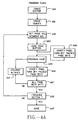
- Fig. 4A is a flow chart illustrating the program flow for the flash EPROM circuit of Fig. 4.
- the process begins by erasing the sector (e.g., sector 170-1) into which data is to be programmed (block 600). After erasing the sector, an erase verify operation is executed (block 601). Next, the page number, either 0 or 1, and the segment number, 1-8, is set by the host processor in response to the input address (block 602).
- the page buffer is loaded with the data for the page (block 603).
- This page buffer may be loaded with an entire N bits of data, or a single byte of data, as suits a particular program operation.
- a verify operation is executed, in case the user does not pre-erase, to determine which cells need programming (block 604).
- the program potentials are applied to the segment being programmed (block 605).
- a verify operation is executed in which the page is verified. In the verify operation, the bits in the page buffer which correspond to successfully programmed cells are turned off (block 606).
- the algorithm determines whether all page bits are turned off in the page buffer (block 607).
- the algorithm determines whether a maximum number of retries has been made (block 610), and if not, loops to block 605 to program the page again, such that the failed bits are reprogrammed.
- the bits which pass are not reprogrammed because the corresponding bits in the page buffer were reset to 0 during the verify operation. If the maximum number of retries has been made at block 610, then the algorithm hangs up, signaling an unsuccessful operation.
- the algorithm determines whether the sector has been finished, that is, whether both pages of the sector are to be written and both are completed (block 608). This is a CPU determined parameter. If the sector is not finished, then the algorithm loops to block 602 and updates the appropriate one of the page number or segment number.
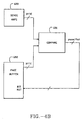
- the program verify circuitry involves resetting on a bit by bit basis, the data in the page buffer which passes erase verify.
- a structure such as shown in simplified form in Fig. 4B is included in the flash EPROM.
- the sense amps 650 of the array are coupled to a compare circuitry 651.
- the inputs to the compare circuitry are the page buffer latches 652.
- a pass/fail signals for the byte are fed back to a bit reset on the page buffer 652.
- bits which pass are reset in the page buffer.
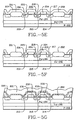
- Figs. 5A-5H illustrate manufacturing steps for a flash EPROM array according to one embodiment of the present invention.
- Figs. 5A-5G are not drawn to scale.
- Fig. 5H is an approximate scale drawing to provide perspective for the resulting structure.
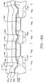
- Figs. 6A-6G provide an alternative approach to manufacturing the flash EPROM cell, which involves the same initial steps, as illustrated in Figs. 5A-5D.
- Fig. 6G is an approximate scale drawing of the resulting structure.
- Figs. 7 and 8-14 are used to describe the layout of a three word line by six column test array for the embodiment described with respect to Figs. 5A-5H, and Fig. 3.
- a well known LOCOS field oxidation process is used to grow relatively thick field oxide regions 201 and 202 which are elongated in a direction perpendicular to the page. Also, a sacrificial oxide layer is grown and then removed to prepare the surface of the p-well 199 for subsequent steps.
- a photomasking process is used to define the floating gates, and n+ source and drain diffusion regions.
- photomask layers 206, 207 are defined to protect the floating gate regions in poly one 204.
- the poly one 204 and nitride layers 205 are etched away except as protected by the masks 206 and 207 to expose the drain, source and drain regions.
- n-type dopants are implanted in the p-well 199 as illustrated at arrows 208 within the exposed regions. These regions are therefore self-aligned to the floating gate in poly one 204 and to the field isolation regions 201 and 202.
- the substrate is annealed to activate the dopants and define the drain diffusion regions 213 and 214, and the source diffusion region 215. Also, drain oxides 216, 217 and source oxide 218 of about 2,000 ⁇ are grown, along with oxides 225 and 226 covering the sides of the floating gate poly 204.
- the nitride layer 205 on the floating gates is removed and then a second layer 219 of poly (poly two) is deposited over the first layer.
- the second layer 219 is about 800 ⁇ thick and deposited on top of poly one. This layer is implanted with an n-type dopant.
- a photomasking process is used to define the poly two pattern, which in turn defines the effective floating gate area as seen from the control gate to be deposited in poly three.
- the effective floating gate area is increased by the poly two deposition so that the coupling ratio is high enough and preferably about or larger than 50%.
- the n-type dopants will uniformly distribute between poly two and poly one layers, resulting in very low resistance contact between the two layers.
- an ONO layer 220 is grown on top of the poly two layer.
- the ONO layer is about 180 ⁇ thick.
- a third poly layer 221 (poly three) is deposited on top of the ONO and, after deposition of tungsten silicide as shown in Fig. 5H, etched to define the word line for the memory cells.
- Fig. 5H illustrates the layer of tungsten silicide 234 over the poly three layer 221 used to improve the conductivity of the word lines.
- Fig. 5H is an approximate scale sketch of the structure of the resulting cell.
- the drain diffusion region 213 is formed in a region between the field oxide 202 and the poly one layer of the floating gate 230, which is about 0.6 microns wide.
- the poly one portion of the floating gate 230 is about 0.6 microns wide.
- the source diffusion region between floating gate regions 230 and 232 is approximately 1.0 microns wide.
- the drain diffusion region 214 is approximately 0.6 microns wide.
- the 1.0 micron wide source diffusion region 215 is formed slightly wider to allow for alignment tolerances for the poly two deposition process. With a more controlled alignment process, the width of the source diffusion region 215 can be reduced.
- the tunnel oxide 203 under the poly one portion of the floating gate electrode 230 or 232 is approximately 90 angstroms thick.
- the poly one deposition 230 is approximately 800 angstroms thick.
- the oxide region 216 over the drain diffusion region 213, and similarly the oxides over the source diffusion region 215 and drain diffusion region 214 as grown are approximately 2,000 to 2,500 angstroms thick, but as finished are in the range of 1,000 to 1,500 angstroms.
- the side wall oxide 226 on the poly one portion of floating gate 230 is in the range of 600 angstroms thick. As can be seen in the sketch, it merges with the thermal oxide 216 over the source or drain diffusion region as appropriate.
- the thickness of the second poly deposition 231 is approximately 800 angstroms.
- the thickness of the ONO layer 220 is approximately 180 angstroms.
- the third poly layer 221 is approximately 2,500 angstroms thick.
- the tungsten silicide layer 234 is approximately 2,000 angstroms thick.
- the field oxide region 202 in the finished product is in the range of 6,500 to 5,000 angstroms thick.
- Fig. 5H illustrates a feature of the process of Figs. 5A-5H.
- the second poly deposition 233 only partially covers the drain diffusion region 214.
- an alternative mask is used to extend the poly two portion of the floating gate across the drain diffusion region partially overlapping the field oxide region 202. This variability in the process allows the coupling ratio of the floating gate to be varied as suits the needs of a particular design by extending its length out over the field oxide region.
- Metallization and passivation layers are deposited over the circuit of Fig. 5H.
- a floating gate structure for a drain-source-drain configured flash EPROM segment which consists of a first layer polysilicon 230 and a second layer polysilicon 231.
- the first layer poly 230 is used for self-alignment of the source and drain diffusion regions.
- the second layer poly 231 is used to extend the floating gate surface area to increase the coupling ratio of the cell.
- the floating gate consisting of poly one layer 230 and poly two layer 231 for the cell on the left side, and the floating gate consisting of poly one layer 232 and poly two layer 233 for the cell on the right side of the figure are essentially mirror images. This allows for extension of the floating gate out over the drain diffusion regions in the drain-source-drain configuration, without shorting over the shared source diffusion region substantially.
- the cell technology and layout has a number of merits.
- the tunnel oxide is grown before the array source/drain implant. Thus, oxide thickening and dopant depletion effects are minimized.
- the source and drain implant of the memory cell is self-aligned to the poly one pattern. Thus, the channel length of the cell can be well controlled.
- the source block transistor merges with the memory cell source/drain diffusion in the cell layout. This overlap region provides interconnection between these two diffusion areas.
- the field oxide is used to isolate the bit line pairs from neighboring bit lines. Inside the bit line pair, the structure is flat.
- the effective gate coupling area seen from the control gate is determined by the area of the second layer of poly. Therefore, a reasonably high gate coupling ratio can be achieved by extending the second layer of poly over the buried diffusion or field oxide regions to compensate for the low gate coupling ratio which would be provided by only the first layer of poly. Further, by extending the length of the extension of the second layer of poly out over the diffusion regions and isolation regions, different gate coupling ratios can be easily achieved to meet different product applications.
- FIG. 6A-6G An alternative cell structure is illustrated with respect to Figs. 6A-6G.
- This structure begins with the same manufacturing steps as shown in Figs. 5A-5D above.
- the sequence proceeds from the structure of Fig. 5D by first removing the masks 206 and 207, and then depositing a nitride layer 250 over the region.
- the nitride layer coats the sides of the floating gate poly 204 as illustrated in the figure.
- an anisotropic etch is used to remove the deposited nitride layer 250, except for those portions of the layer on the top and sides of the floating gate poly 204.
- the etch may leave a small amount of nitride on the edges of the field oxide regions 201, 202. However, this is not important to the process.
- the wafer is annealed to drive-in the dopants to form the drain diffusion regions 213 and 214 and the source diffusion region 215. Also, the thermal oxides 216, 217, and 218 are grown over the drain diffusion regions and the source diffusion region, respectively.
- the nitride layers 205 and 250 protect the floating gate poly 204 from oxide formation.
- the nitride remnants of the layer 205 and the layer 250 are removed from the structure, exposing the poly one floating gate elements 204.
- a second poly deposition 219 is deposited on the structure.
- This second layer poly 219 is deposited to a thickness of about 1,500 to 2,000 angstroms and implanted with an n-type dopant.
- poly spacers 240 and 241 are formed along the edges of the poly one pattern using a self-aligned plasma etching of the poly two layer.
- the n-type dopants in the poly two deposition will distribute evenly between the poly one and poly two elements, and provide good electrical contact.
- an ONO layer 220 is deposited over the floating gate structures formed of the poly one element, 242, and the poly two spacers 240 and 241. Also, a region of polysilicon 243 may be left adjacent the field oxide region 201 in this process. However, there is no electrical contact in this region and it should not have an affect on the operation of the device.
- a third poly layer 221 is deposited having a thickness of about 2,500 angstroms to form the word lines for the device.
- Fig. 6G illustrates the last step in the process of depositing a layer of tungsten silicide 234 having a thickness of about 2,000 angstroms over the poly three word line 221 to improve the conductivity of the structure.
- Fig. 6G is also an approximate scale sketch of the structure.
- the drain diffusion regions 213 and 214 are formed in a region between a field oxide 202 and the floating gate 204 of about 0.6 microns in width.
- the floating gate poly one deposition 204 is about 0.15 microns in thickness.
- the source diffusion region 215 formed between the poly one floating gates is about 0.6 microns in this embodiment.
- the narrower source diffusion region 215 as compared to that of Fig. 5H, is possible in this approach because of the self-aligned nature of the poly two spacers 240 and 241. There is no need in a layout of a structure as shown in Fig.
- FIG. 6G to provide for mask misalignment tolerances necessary for aligning the mask to form the poly two floating gate extensions of Fig. 5H. This makes the structure of Fig. 6G scalable, as process dimensions shrink, without requirement for allowing for mask misalignment tolerances.
- the thicknesses of the regions in the vertical dimensions are similar to those of Fig. 5H.
- the poly one deposition 242 is about 1,500 to 1,600 angstroms thick.
- the spacers 240 and 241 extend about 2,000 angstroms out over the source and drain diffusion regions.
- the second nitride layer 250 is not deposited.
- oxide will grow on the side of the poly one deposition. These oxides on the sides of the poly can be etched away, so that contact between poly one and poly two may be provided in the subsequent steps.
- the etching of the oxide on the side of the poly one portion of the floating gate will risk etching of the oxide between the floating gate and the substrate. If this region is etched too far, then a short may occur during the poly two deposition to the substrate.
- the procedure illustrated in Fig. 6A-6G may be preferred for many applications.
- the polysilicon used in the described structure for the floating gate can be replaced with amorphous silicon.
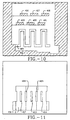
- Figs. 7-14 are used to describe the layout of a test array which is 6 columns by 3 word lines in size.
- Fig. 7 is a composite view which will be understood better with reference to the layout views of Figs. 8-14.
- the test array includes five field isolation regions 400, 401, 402, 403, and 404.
- the layout of these isolation regions can be seen with reference to Fig. 8 where the field oxide regions are marked with reference numerals 400-404, and the hatched region 405 corresponds to an active region inside the p-type well 199 of Fig. 5G.
- Fig. 9 illustrates the layout of a p-type implant which is used to raise the threshold voltage VT of the memory cells.
- the implant in area 406 causes a higher initial VT for the memory cells in the block than for the select transistors (in regions circled by lines 436 and 437 of Fig. 7).
- the array also includes the poly three control lines 407 and 408 for the right and left select transistors for each of the three segments, respectively.
- Fig. 7 also shows three word lines 409, 410, and 411 which overlay three segments of the array.
- the first layer poly is illustrated in Fig. 7 by the bold outline 415 and is also more clearly seen in Fig. 10.
- Fig. 10 illustrates the masking for the poly one deposition. Poly one is deposited and etched inside the region defined by the line 415, and in the regions surrounding the layout on Fig. 10, to establish the first layer poly of the floating gates of Fig. 5G.
- Fig. 11 illustrates the masking pattern for the second layer poly for the cell illustrated in Fig. 5G.
- Regions 412, 413, and 414 are apparent in Fig. 7.
- Regions 422 and 423 correspond to segments of the floating gate poly over the field isolation areas 401 and 403 of Fig. 7.
- Poly two is later patterned to establish the extended floating gate of Fig. 5G.
- Fig. 12 illustrates the layout of the poly three control lines 407 and 408 and the word lines 409, 410, and 411.
- Fig. 13 illustrates the metal contacts 424, 425, 426, 427, 428, and 429 in the test array.
- the contact 424 is used to contact the poly three control line 408.
- the contact 428 is used for making a metal contact to the poly three control line 407.
- Contacts 425, 426, and 427 are used for making contact from the diffusion region of the select transistors to the metal global bit lines which overlay the array (not shown in Fig. 7).
- Contact 429 is used for making contact to the array source diffusions.
- the layout of the metal lines is shown in Fig. 14. As can be seen, they align with the contacts 425, 426, and 427 and overlay the segments in the array.
- metal bit line 430 is coupled to contact 425
- metal bit line 431 is coupled to contact 426
- metal bit line 432 is coupled to contact 427.
- the metal pads 433 and 434 are coupled to contacts 428 and 424, respectively.
- the metal pad 435 is coupled to contact 429.
- a field isolation and diffusion step is shown in Fig. 8.
- a VT enhancement implant step is carried out in the region 406 shown in Fig. 9.
- the floating gate poly is laid down.
- the segments 416 through 421 are laid down with poly one to establish the channels for the left and right block select transistors.
- a source/drain implant is executed to form the drain-source-drain structure and the buried diffusions for the left and right block select transistors and the virtual ground terminal.
- the poly two is deposited, as illustrated in Fig. 11.
- Poly two is patterned as described above to establish the extended floating gates.
- An insulating layer is placed over poly two and the third layer of poly is deposited with a pattern as shown in Fig. 12.
- isolation is deposited over the poly three layer, the metal contacts are made, and the metal bit lines are deposited overlaying the array.
- the current path from the contact 425 to the left diffusion region for the segment is illustrated by the arrow line 443. As can be seen, this path is interrupted by the transistor channel in the region 442. Thus, the control line 408 provides for connection of the left drain diffusion region to the contact 425.
- the current path for the right block select transistor is illustrated by the arrow line 444. As can be seen, this path is interrupted by the channel in the region 440.
- a new flash EPROM cell and array architecture have been provided.
- the architecture provides for a very dense core array obtained by unique cell layouts, where two adjacent local drain bit lines share one common source bit line.
- the layout has been optimized to allow use of a single metal line for every two columns of cells in the array.
- the layout is further reduced by shared word lines, so that the word line driver pitch does not impact the size of the main array.
- Sector erase is feasible using segmentable architecture of the present invention.
- row redundancy is available for flash EPROM using this structure. A high performance, reliable flash memory array can be achieved using these technologies.
- n-channel embodiment of the flash EPROM array has been disclosed.
- p-channel equivalent circuits can be implemented using techniques known in the art.
- the architecture has been designed with respect to flash EPROM cells. Many aspects of the architecture may be adapted to a variety of memory circuit arrays.
Landscapes
- Engineering & Computer Science (AREA)
- Microelectronics & Electronic Packaging (AREA)
- Physics & Mathematics (AREA)
- General Physics & Mathematics (AREA)
- Semiconductor Memories (AREA)
- Non-Volatile Memory (AREA)
- Read Only Memory (AREA)
Claims (39)
- Integrierter Flash-EPROM-Schaltkreismodul auf einem Halbleitersubstrat mit:einem Speicherarray, welches zumindest M Reihen und 2N Spalten von Flash-EPROM-Zellen aufweist,M-Wortleitungen (WL0-WL63), wobei jede Wortleitung mit den Flash-EPROM-Zellen in einer entsprechenden der M Reihen von Flash-EPROM-Zellen verbunden ist,einer Mehrzahl globaler Bitleitungen,einem Bezugsleiter (ARVSS), der orthogonal zu den globalen Bitleitungen verläuft,Datenein- und -ausgabeschaltkreisen (103, 107), die mit der Mehrzahl globaler Bitleitungen verbunden sind, welche das Lesen und Schreiben von Daten in dem Speicherarray bereitstellen,wobei die 2N Spalten von Flash-EPROM-Zellen in dem Speicherarray aufweisen:N Paare aus Spalten von Flash-EPROM-Zellen, wobei jedes Paar von Spalten eine Mehrzahl von. Segmenten aufweist, und wobei jedes Segment in der Mehrzahl aufweist:eine erste (121) und eine zweite (123) lokale Bitleitung,eine lokale Sourceleitung (122), die mit dem Bezugsleiter verbunden ist,einen ersten Satz aus Flash-EPROM-Zellen (124-127) in einer ersten Spalte des Paares von Spalten, welche mit der ersten lokalen Bitleitung (121) verbunden ist,einen zweiten Satz von Flash-EPROM-Zellen (128-131) in einer zweiten Spalte des Paares von Spalten, die mit der zweiten lokalen Bitleitung (123) verbunden ist,wobei Mitglieder eines Teilsatzes der M Wortleitungen jeweils mit einer Flash-EPROM-Zelle in dem ersten Satz und einer Flash-EPROM-Zelle in dem zweiten Satz verbunden sind,wobei der integrierte Schaltkreismodul dadurch gekennzeichnet ist, daßdie Mehrzahl von globalen Bitleitungen N globale Bitleitungen (MTBL0, MTBL1) aufweist,und ein Auswahlschaltkreis (139, 138) mit den 2N Spalten aus Flash-EPROM-Zellen und den N globalen Bitleitungen (MTBL0, MTBL1) verbunden ist, wobei der Auswahlschaltkreis (139, 138) einen Segmentauswahlschaltkreis aufweist, der mit den beiden lokalen Bitleitungen (121, 123) und zumindest einer der N globalen Bitleitungen (MTBL0, MTBL1) verbunden ist, was eine erste ausgewählte Verbindung der ersten und zweiten Sätze in dem Segment mit der zumindest einen der N globalen Bitleitungen (MTBL0, MTBL1) bereitstellt, so daß für den Dateneingabe- und - ausgabeschaltkreis (103, 107) über die N globalen Bitleitungen (MTBL0, MTBL1) Zugriff auf die 2N Spalten von Flash-EPROM-Zellen bereitgestellt wird.
- Integrierter Schaltkreismodul nach Anspruch 1, wobei der erste Satz aus Flash-EPROM-Zellen zwischen die erste lokale Bitleitung und die lokale Sourceleitung geschaltet ist und wobei der zweite Satz von Flash-EPROM-Zellen zwischen die zweite lokale Bitleitung und die lokale Sourceleitung geschaltet ist.
- Integrierter Schaltkreismodul nach Anspruch 2, einschließlich einer Isolierschicht über den 2N Spalten, und wobei die N globalen Bitleitungen (MTBL0, MTBL1) über der Isolierschicht liegen und der Segmentauswahlschaltkreis einen Kontakt (140) durch die Isolierschicht zu einer entsprechenden der N globalen Bitleitungen (MTBL0) aufweist und eine Schaltung mit dem Kontakt (140) und den beiden lokalen Bitleitungen (121, 123) verbunden ist, um die beiden lokalen Bitleitungen (121, 123) mit dem Kontakt (140) in Verbindung zu bringen.
- Integrierter Schaltkreismodul nach Anspruch 3, wobei ein Segmentauswahlschaltkreis für jedes Segment einen ersten Transistor (139) aufweist, der einen ersten Anschluß in der ersten lokalen Bitleitung (121) und einen zweiten Anschluß hat, der mit dem Kontakt (140) verbunden ist, und ein zweiter Transistor (138) einen ersten Anschluß in der zweiten lokalen Bitleitung (123) hat und ein zweiter Anschluß mit dem Kontakt (140) verbunden ist.
- Integrierter Schaltkreismodul nach Anspruch 1, einschließlich:einer Reihendecoderschaltung, um die M Wortleitungen anzusteuern, wobei die Reihendecoderschaltung weniger als M Treiber aufweist und wobei jeder der weniger als M Treiber einen Satz von mehr als einer der M Wortleitungen parallel treibt bzw. ansteuert, wenn er durch den Reihendecoderschaltkreis freigeschaltet wird.
- Integrierter Schaltkreismodul nach Anspruch 1, wobei das Halbleitersubstrat einen Substratbereich (200) eines ersten Leitfähigkeitstyps hat, einen ersten Well (198) in dem Substratbereich (200) eines zweiten Leitfähigkeitstyps hat, und einen zweiten Well (199) des ersten Leitfähigkeitstyps in dem ersten Well (198) hat, und wobei die Flash-EPROM-Zellen Sources und Drains haben, die in dem zweiten Well (199) ausgebildet sind, um während eines Vorganges zum Verändern gespeicherter Inhalte der Zellen ein negatives Potential an zumindest einer, nämlich der Source oder der Drain, anzulegen.
- Integrierter Schaltkreismodul nach Anspruch 1, wobei es mehr als 2N Spalten gibt und wobei der Auswahlschaltkreis (138, 139) eine selektive Verbindung von mehr als zwei Spalten mit zumindest einer der N globalen Bitleitungen bereitstellt, so daß Zugriff auf die mehr als 2N Spalten von Flash-EPROM-Zellen durch die Dateneingabe- und -ausgabeschaltung (103, 107) über die N globalen Bitleitungen (MTBL0, MTBL1) bereitgestellt wird.
- Integrierter Schaltkreismodul nach Anspruch 1, wobei:wobei der Bezugsleiter (ARVSS) mit der Mehrzahl von Sourcediffusionsbereichen (215) verbunden ist.das Speicherarray ein Array aus Transistoren mit erdfreiem Gate in einem Substratbereich (200) eines ersten Leitfähigkeitstyps in einem Halbleitersubstrat aufweist, mit:einer Mehrzahl von beabstandeten, relativ dicken Isolierbereichen (201, 202) in dem Substrat, die sich in einer ersten Richtung länglich erstrecken, um eine Mehrzahl isolierter Bereiche in dem Substratbereich bereitzustellen,einer Mehrzahl erster Draindiffusionsbereiche (213) in den entsprechenden isolierten Bereichen, die länglich in der ersten Richtung verlaufen, und jeweils auf einer Seite mit einem entsprechenden aus der Mehrzahl von Isolierbereichen (201) ausgerichtet sind,einer Mehrzahl von Sourcediffusionsbereichen (215) in den entsprechenden isolierten Bereichen, die länglich in der ersten Richtung verlaufen und jeweils von den ersten Draindiffusionsbereichen (213) beabstandet sind, um einen ersten Kanalbereich zwischen den Source- und ersten Draindiffusionsbereichen (213) in den entsprechenden isolierten Bereichen bereitzustellen,einer Mehrzahl von zweiten Draindiffusionsbereichen (214) in den entsprechenden isolierten Bereichen, die länglich in der ersten Richtung verlaufen und jeweils auf einer Seite mit einer entsprechenden aus der Mehrzahl von Isolierbereichen (202) ausgerichtet und von dem Sourcediffusionsbereich (215) beabstandet sind, um einen zweiten Kanalbereich zwischen den Source- und zweiten Draindiffusionsbereichen (214) in den entsprechenden isolierten Bereichen bereitzustellen,einer ersten Isolierschicht (203) auf dem Substrat über den ersten und zweiten Kanalbereichen, über dem Sourcediffusionsbereich (215) und über den ersten und zweiten Draindiffusionsbereichen (213, 214) in den entsprechenden isolierten Bereichen,einer ersten Mehrzahl von erdfreien Gateelektroden (230) über der ersten Isolierschicht (203) über den ersten Kanalbereichen in der Mehrzahl von Isolationsbereichen,einer zweiten Mehrzahl von erdfreien Gateelektroden (232) über der ersten Isolierschicht (203) über den zweiten Kanalbereichen in der Mehrzahl von Isolationsbereichen,einer zweiten Isolierschicht (220) über den ersten und zweiten Mehrzahlen von erdfreien Gateelektroden (230, 232),wobei die M Wortleitungen eine Mehrzahl von Wortleitungsleitern (221) über der zweiten Isolierschicht (220) aufweisen, welche länglich in einer zweiten Richtung verlaufen und welche jeweils über der Mehrzahl dicker Isolationsbereiche über den Sourcediffusionsbereichen (215) und den ersten und zweiten Draindiffusionsbereichen (213, 214) verlaufen und über einer erdfreien Gateelektrode (230) in der ersten Mehrzahl und einer erdfreien Gateelektrode (232) in der zweiten Mehrzahl verlaufen, um eine Mehrzahl von Paaren aus erdfreien Gatetransistoren in den entsprechenden Isolationsbereichen zu bilden, die gemeinsame Sourcediffusionsbereiche haben,die N globalen Bitleitungen eine Mehrzahl von Datenleitern (430, 431, 432) aufweisen,und wobei der integrierte Schaltkreismodul weiterhin aufweist:eine Mehrzahl von Auswahlschaltungen, die jeweils einen Kontakt mit einem entsprechenden aus der Mehrzahl von Datenleitern (430, 431, 432) haben und die mit einem entsprechenden ersten Draindiffusionsbereich aus der Mehrzahl erster Draindiffusionsbereiche (213) und einem entsprechenden zweiten Draindiffusionsbereich aus der Mehrzahl von zweiten Draindiffusionsbereichen (214) verbunden sind, wobei wahlweise Strom zwischen dem entsprechenden aus der Mehrzahl von Datenleitern (430, 431, 432) und einem von den entsprechenden ersten Draindiffusionsbereichen (213) und den entsprechenden zweiten Draindiffusionsbereichen (214) gategesteuert fließt, und
- Integrierter Schaltkreismodul nach Anspruch 8, welcher weiterhin aufweist:eine Bitleitungsisolierschicht (234) über den M Wortleitungen, wobei die Datenleiter (430, 431, 432) über der Bitleitungsisolierschicht (234) verlaufen.
- Integrierter Schaltkreismodul nach Anspruch 9, wobei die M Wortleitungen Polysilicium aufweisen und die Datenleiter (430, 431, 432) Metall aufweisen.
- Integrierter Schaltkreismodul nach Anspruch 8, wobei zumindest ein Auswahlschaltkreis in der Mehrzahl von Auswahlschaltkreisen einen Kontakt mit einem aus der Mehrzahl von Datenleitern (430, 431, 432) aufweist, wobei ein erster Transistor einen ersten Anschluß in einem entsprechenden ersten Draindiffusionsbereich (213) und einen zweiten Anschluß hat, der mit dem Kontakt verbunden ist, und ein zweiter Transistor einen ersten Anschluß in einem entsprechenden. zweiten Draindiffusionsbereich (214) sowie einen zweiten Anschluß hat, der mit dem Kontakt verbunden ist.
- Integrierter Schaltkreismodul nach Anspruch 8, welcher weiterhin einen ersten Well eines zweiten Leitfähigkeitstyps in dem Substratbereich (200) und einen zweiten Well des ersten Leitfähigkeitstyps in dem ersten Well hat, und wobei die Mehrzahl von ersten Draindiffusionsbereichen (213), die Mehrzahl von Sourcediffusionsbereichen (215) und die Mehrzahl von zweiten Draindiffusionsbereichen (214) innerhalb des zweiten Wells ausgebildet sind, um das Anlegen eines negativen Potentials an zumindest einem, nämlich der Source oder der Drain, während eines Vorganges zum Verändern gespeicherter Inhalte der Zelle zu ermöglichen.
- Integrierter Schaltkreismodul nach Anspruch 1, wobei das Halbleitersubstrat einen Substratbereich (200) eines ersten Leitfähigkeitstyps hat, mit:so daß jedes Segment einen ersten Satz aus Flash-EPROM-Zellen in einer ersten aus dem Paar von Spalten und einen zweiten Satz von Flash-EPROM-Zellen in einer zweiten aus dem Paar von Spalten aufweist,einem ersten Well aus einem zweiten Leitfähigkeitstyp in dem Substratbereich (200) und einem zweiten Well des ersten Leitfähigkeitstyps in dem ersten Well,wobei die 2N Spalten von Flash-EPROM-Zellen in dem Speicherarray aufweisen:N Paare aus Spalten von Flash-EPROM-Zellen, wobei jedes Paar von Spalten eine Mehrzahl von Segmenten aufweist, jedes Segment in der Mehrzahl einen ersten Draindiffusionsbereich (213) aufweist, der in der ersten Richtung länglich in dem zweiten Well verläuft,einen Sourcediffusionsbereich (215), der länglich in der ersten Richtung in dem zweiten Well verläuft und von dem ersten Draindiffusionsbereich (213) beabstandet ist, um einen ersten Kanalbereich zwischen der Source und ersten Draindiffusionsbereichen (215, 213) bereitzustellen,einen zweiten Draindiffusionsbereich (214), der in der ersten Richtung in dem zweiten Well länglich verläuft und von dem Sourcediffusionsbereich (215) beabstandet ist, um einen zweiten. Kanalbereich zwischen der Source und zweiten Draindiffusionsbereichen (215, 214) bereitzustellen,eine erste Isolierschicht (203) über dem Substrat, über den ersten und zweiten Kanalbereichen, über dem Sourcediffusionsbereich (215) und über den ersten und zweiten Draindiffusionsbereichen (213, 214),eine erste Mehrzahl von erdfreien Gateelektroden (230) über der ersten Isolierschicht (203) über den ersten Kanalbereichen,eine zweite Mehrzahl von erdfreien Gateelektroden (232) über der ersten Isolierschicht (203) über den zweiten Kanalbereichen, undeine zweite Isolierschicht (220) über den ersten und zweiten Mehrzahlen von erdfreien Gateelektroden (230, 232),
wobei Mitglieder eines Teilsatzes der M Wortleitungen jeweils mit einer Flash-EPROM-Zelle in dem ersten Satz in einem gegebenen Segment und einer Flash-EPROM-Zelle in dem zweiten Satz in dem gegebenen Segment verbunden sind,
wobei die Dateneingabe- und -ausgabeschaltkreise (103, 107) mit den N globalen Bitleitungen verbunden sind, welche das Lesen und Schreiben von Daten in 2N Spalten von Flash-EPROM-Zellen bereitstellen, und
wobei der Auswahlschaltkreis so mit den ersten und zweiten Draindiffusionsbereichen (213, 214) in der Mehrzahl von Segmenten und damit mit den 2N Spalten aus Flash-EPROM-Zellen und den N globalen Bitleitungen (MTBL0, MTBL1) verbunden ist, was eine wahlweise Verbindung zweier Spalten der 2N Spalten mit jeder der N globalen Bitleitungen (MTBL0, MTBL1) bereitstellt, so daß der Zugriff auf die 2N Spalten von Flash-EPROM-Zellen durch den Dateneingabe- und -ausgabeschaltkreis (103, 107) über die N globalen Bitleitungen (MTBL0, MTBL1) bereitgestellt wird,
wobei der integrierte Schaltkreismodul weiterhin eine Programmierschaltung (108, 109) aufweist, die während eines Vorganges zum Entladen von erdfreien Gateelektroden ausgewählter Flash-EPROM-Zellen ein negatives Potential an Wortleitungen anlegt und ein negatives Potential an zumindest einen der Sourcediffusionsbereiche (215) und Draindiffusionsbereiche (213, 214) während eines Vorganges Zellen anlegt. - Integrierter Schaltkreismodul nach Anspruch 13, wobei die Segmente weiterhin aufweisen
eine Wortleitungsisolierschicht (220) über den ersten und zweiten Mehrzahlen von Elektroden mit erdfreiem Gate, wobei die M Wortleitungen über der Isolierschicht (220) der Wortleitung verlaufen, und
eine Bitleitungsisolierschicht über den M Wortleitungen, wobei die N globalen Bitleitungen (MTBL0, MTBL1) über der Isolierschicht (220) der Wortleitung liegen. - Integrierter Schaltkreismodul nach Anspruch 14, wobei die M Wortleitungen Polysilicium aufweisen und die N globalen Bitleitungen (MTBL0, MTBL1) Metall aufweisen.
- Integrierter Schaltkreismodul nach Anspruch 13, wobei der Auswahlschaltkreis (139, 138) für jedes Segment einen Kontakt (140) durch die isolierende Schicht zu einer entsprechenden der N globalen Bitleitungen aufweist und der Schaltkreis mit dem Kontakt (140) und mit den ersten und zweiten Draindiffusionsbereichen (213, 214) verbunden ist, um wahlweise die ersten und zweiten Draindiffusionsbereiche (213, 214) mit dem Kontakt zu verbinden.
- Integrierter Schaltkreismodul nach Anspruch 16, wobei der Auswahlschaltkreis (138, 139) für jedes Segment einen ersten Transistor umfasst, der einen ersten Anschluß in dem ersten Draindiffusionsbereich (213) sowie einen zweiten Anschluß hat, der mit dem Kontakt (140) verbunden ist, und einen zweiter Transistor umfasst, der einen ersten Anschluß in dem zweiten Draindiffusionsbereich hat und der einen zweiten Anschluß hat, der mit dem Kontakt (140) verbunden ist.
- Integrierter Schaltkreismodul nach Anspruch 13, mit:
einem Reihendetektorschaltkreis (114), um die M Wortleitungen anzusteuern, wobei der Reihendecoderschaltkreis (104) weniger als M Treiber aufweist, wobei jeder der weniger als M Treiber einen Satz von mehr als einer der M Wortleitungen parallel treibt, wenn er durch den Reihendecoderschaltkreis (104) freigeschaltet worden ist, wobei der Satz von Wortleitungen, die parallel angesteuert werden, höchstens eine Wortleitung hat, die mit Flash-EPROM-Zellen in einem gegebenen der Mehrzahl von Segmenten verbunden ist, die mit einer gegebenen globalen Bitleitung (MTBL0, MTBL1) verbunden sind. - Integrierter Schaltkreismodul nach Anspruch 13, welcher weiterhin relativ dicke Isolationsbereiche (201, 202) aufweist, die sich parallel zu den ersten und zweiten Draindiffusionsbereichen (213, 214) in den Segmenten erstrecken, um die Segmente voneinander zu isolieren.
- Integrierter Schaltkreismodul nach Anspruch 13, welcher weiterhin einen Satz von Redundanzsegmenten (183-1, 183-2) aufweist, wobei zumindest ein Redundanzsegment in dem Satz mit der globalen Bitleitung verbunden ist, welche jedem der Paare von Spalten von Flash-EPROM-Zellen entspricht, und einen redundanten Decoderschaltkreis (186) aufweist, der mit dem Satz von Redundanzsegmenten (183-1, 183-2) verbunden ist und der so programmierbar ist, daß er eine oder mehrere Reihen von Zellen aus den 2N Spalten von Zellen durch eine oder mehrere Reihen von Zellen in dem Satz von Redundanzsegmenten (183-1, 183-2) ersetzt.
- Integrierter Schaltkreismodul nach Anspruch 1, wobei jede Flash-EPROM-Zelle des Speicherarrays einen Flash-EPROM-Transistor in dem Halbleitersubstrat aufweist, der einen ersten Bereich (200) eines ersten Leitfähigkeitstyps hat, mit:einem ersten Well (198) in dem ersten Bereich (200) aus einem zweiten Leitfähigkeitstyp, und einen zweiten Well (199) des ersten Leitfähigkeitstyps in dem ersten Well (198),einem kontaktfreien Draindiffusionsbereich (213, 214) aus dem zweiten Leitfähigkeitstyp in dem zweiten Well (199),einem kontaktfreien Sourcediffusionsbereich (215) des zweiten Leitfähigkeitstyps in dem zweiten Well (199), welcher von dem Draindiffusionsbereich (214, 213) beabstandet ist, um einen Kanalbereich zwischen den Source- und Draindiffusionsbereichen (213, 214, 215) bereitzustellen,einer ersten Isolierschicht (203) auf dem Substrat, auf dem Kanalbereich und auf den Source- und Draindiffusionsbereichen (213, 214, 215),einer erdfreien Gateelektrode (230, 232), die über der ersten Isolierschicht (203) über dem Kanalbereich liegt,einer zweiten Isolierschicht (220) über der erdfreien Gateelektrode (230, 232),einer Steuergateelektrode über der zweiten Isolierschicht (220) über der erdfreien Gateelektrode (230, 232), um über dem Kanalbereich einen Flash-EPROM-Transistor zu bilden,wobei der integrierte Schaltkreismodul weiterhin aufweist:eine Quelle eines negativen Potentials (108), die so angeschlossen ist, daß sie ein negatives Potential an zumindest einem, nämlich der Diffusionsbereiche (213, 214) und/oder dem Sourcediffusionsbereich (215) während eines Vorganges zum Verändern einer Ladungsmenge in der erdfreien Gateelektrode anzulegen.
- Integrierter Schaltkreismodul nach Anspruch 1, wobei das Speicherarray ein Flash-EPROM-Transistorarray in dem Halbleitersubstrat aufweist, welches einen Substratbereich (200) eines ersten Leitfähigkeitstyps hat, mit:einem ersten Well (198) eines zweiten Leitfähigkeitstyps in dem Substratbereich (200), und einem zweiten Well (199) des ersten Leitfähigkeitstyps in dem ersten Well (198),einem kontaktfreien Draindiffusionsbereich (213, 214) des zweiten Leitfähigkeitstyps in dem zweiten Well (199), welcher länglich in einer ersten Richtung verläuft,einem kontaktfreien Sourcediffusionsbereich (215) des zweiten Leitfähigkeitstyps in dem zweiten Well (199), welcher länglich in der ersten Richtung und von dem Draindiffusionsbereich (213, 214) beabstandet verläuft, um zwischen den Source- und Draindiffusionsbereichen (213, 214, 215) einen Kanalbereich bereitzustellen,einer ersten Isolierschicht (203) auf dem Substrat, auf dem Kanalbereich und auf den Source- und Draindiffusionsbereichen (213, 214, 215),einer Mehrzahl von erdfreien Gateelektroden (230, 232), die über bzw. auf der ersten Isolierschicht (203) über dem Kanalbereich liegen,einer zweiten Isolierschicht (220) über der Mehrzahl aus erdfreien Gateelektroden (230, 232),einer Mehrzahl von Steuergateelektroden auf bzw. über der zweiten Isolierschicht (220), die länglich in einer zweiten Richtung verlaufen, welche die Source- und Draindiffusionsbereiche (213, 214, 215) schneidet, über den entsprechenden erdfreien-Gateelektroden (230, 232), um eine Mehrzahl von Flash-EPROM-Transistoren über dem Kanalbereich zu bilden,wobei jede der N globalen Bitleitungen einen Datenleiter (430, 431, 432) aufweist,und wobei der integrierte Schaltkreismodul weiterhin aufweist:ein Gate, welches Kontakt zu dem Datenleiter (430, 431, 432) hat und einen Diffusionsbereich hat, der mit dem kontaktfreien Diffusionsbereich (213, 214) verbunden ist und welches gategesteuert Strom zwischen dem Datenleiter (430, 431, 432) und dem kontaktfreien Draindiffusionsbereich (213, 214) fließen läßt undeine Quelle eines negativen Potentials (108), welche so angeschlossen ist, daß sie ein negatives Potential an zumindest einem, nämlich dem kontaktfreien Draindiffusionsbereich (213, 214) und/oder dem kontaktfreien Sourcediffusionsbereich (415) während eines Vorganges zum Verändern der Ladungsmenge an zumindest einer aus der Mehrzahl von erdfreien Gateelektroden anlegt.
- Integrierter Flash-EPROM-Schaltkreismodul nach Anspruch 1, wobei:die N globalen Bitleitungen eine Mehrzahl von Bitleitungen aufweisen, wobei jede aus der Mehrzahl von Bitleitungen mit den Flash-EPROM-Zellen in einer entsprechenden der 2N Spalten aus Flash-EPROM-Zellen verbunden ist,die Dateneingabe- und -ausgabeschaltung mit der Mehrzahl von Bitleitungen verbunden ist, was ein Lesen und Schreiben von Daten in dem Speicherarray bereitstellt,wobei der integrierte Schaltkreismodul weiterhin aufweist:ein Redundanzarray (183-1, 183-2), welches zumindest X und 2N Spalten aus Flash-EPROM-Zellen umfaßt, wobei die Flash-EPROM-Zellen in den 2N Spalten des Redundanzarrays (183-1, 183-2) mit der Mehrzahl von Bitleitungen verbunden sind,X redundante Wortleitungen, welche jeweils mit den Flash-EPROM-Zellen in einer der X Reihen von Flash-EPROM-Zellen in dem Redundanzarray (183-1, 183-2) verbunden sind, undeine Redundanzdecoderschaltung (186), die mit den X redundanten Wortleitungen in dem Redundanzarray (183-1, 183-2) verbunden ist, und die so programmierbar ist, daß sie eine oder mehrere Reihen von Zellen aus dem Speicherarray durch eine oder mehrere Reihen von Zellen in dem Redundanzarray (183-1, 183-2) ersetzt.
- Integrierter Schaltkreismodul nach Anspruch 23, wobei jedes Segment in der Mehrzahl weiterhin aufweist:eine lokale Sourceleitung (122), die mit einem Sourcebezugsschaltkreis verbunden ist,wobei der erste Satz aus Flash-EPROM-Zellen zwischen die erste lokale Bitleitung und die lokale Sourceleitung (122) geschaltet ist,der zweite Satz von Flash-EPROM-Zellen zwischen die zweite lokale Bitleitung und die lokale Sourceleitung (122) geschaltet ist,und weiterhin aufweist:eine Schaltung zum Außerbetriebsetzen des Segmentauswahlschaltkreises für zumindest einen Teilsatz aus der Mehrzahl von Segmenten, wenn der Redundanzdecoderschaltkreis (186) auf das Redundanzarray (183-1, 183-2) zugreift.
- Integrierter Schaltkreismodul nach Anspruch 24, wobei die Mehrzahl aus Bitleitungen N Bitleitungen umfaßt und der Segmentauswahlschaltkreis für jedes Segment mit einer einzigen der N Bitleitungen verbunden ist, so daß der Zugriff auf die 2N Spalten aus Flash-EPROM-Zellen durch den Dateneingabe- und -ausgabeschaltkreis (103, 107) über N Bitleitungen bereitgestellt wird.
- Integrierter Schaltkreismodul nach Anspruch 25, einschließlich einer Isolierschicht (220) auf den 2N Spalten, und wobei die N Bitleitungen über der Isolierschicht (220) liegen und die Segmentauswahlschaltung einen Kontakt (140) durch die Isolierschicht zu einer entsprechenden der N Bitleitungen aufweist, und eine Schaltung mit dem Kontakt (140) und den beiden lokalen Bitleitungen (121, 123) verbunden ist, um wahlweise die beiden lokalen Bitleitungen (121, 123) mit dem Kontakt (140) zu verbinden.
- Integrierter Schaltkreismodul nach Anspruch 23, wobei das Redundanzarray (183-1, 183-2) einen Satz von redundanten Segmenten aufweist, wobei zumindest ein redundantes Segment in dem Satz mit einer Bitleitung verbunden ist, die jeder der Paare von Spalten von Flash-EPROM-Zellen entspricht, und wobei der Redundanzdecoderschaltkreis (186) Schaltkreise umfaßt, die mit den Sätzen redundanter Segmente verbunden und so programmierbar sind, daß sie eine oder mehrere Reihen von Zellen aus den 2N Spalten von Zellen durch eine oder mehrere Reihen von Zellen in dem Satz von redundanten Segmenten ersetzen.
- Integrierter Schaltkreismodul nach Anspruch 24, wobei die lokalen Bitleitungen (121, 123) und die lokale Sourceleitung (122) in der Mehrzahl von Segmenten eingegrabene Diffusionsbereiche in dem Halbleitersubstrat aufweisen.
- Integrierter Schaltkreismodul nach Anspruch 28, wobei der Segmentauswahlschaltkreis für jedes Segment einen ersten Transistor umfaßt, der einen ersten Anschluß in dem eingegrabenen Diffusionsbereich einer der lokalen Bitleitungen (121) und einen zweiten Anschluß aufweist, der mit dem Kontakt (140) verbunden ist, und einen zweiten Transistor, der mit einem ersten Anschluß in dem eingegrabenen Diffusionsbereich der anderen der lokalen Bitleitungen (123) liegt und mit einem zweiten Anschluß mit dem Kontakt (140) verbunden ist.
- Integrierter Schaltkreismodul nach Anspruch 24, mit:einer Reihendecoderschaltung (177), um die M Wortleitungen zu treiben bzw. anzusteuern, wobei der Reihendecoderschaltkreis (177), weniger als M Reihen Treiber aufweist und wobei jeder der weniger M Reihen Treiber einen Satz von mehr als einer der M Wortleitungen parallel ansteuert, wenn er durch die Reihendecoderschaltung (177) freigeschaltet wird, wobei der Satz von Wortleitungen, die parallel angesteuert werden, zumindest eine Wortleitung umfassen, die mit Flash-EPROM-Zellen in einem gegebenen aus der Mehrzahl von Segmenten verbunden ist, die mit einer gegebenen Bitleitung verbunden sind, und wobeider Redundanzdecoder (186) Treiber umfaßt für das Ersetzen aller Reihen, die von einem gegebenen Reihentreiber in dem Speicherarray angesteuert werden, durch Reihen in dem Redundanzarray (183-1, 183-2).
- Integrierter Schaltkreismodul nach Anspruch 1, wobei:wobei die Mehrzahl von Spalten von Flash-EPROM-Zellen eine Anzahl von Sätzen von Spalten umfaßt, wobei jeder Satz von Spalten aufweist:das Speicherarray eine Mehrzahl von Reihen und eine Mehrzahl von Spalten aus Flash-EPROM-Zellen aufweist,die M Wortleitungen eine Mehrzahl von Wortleitungen aufweisen, wobei jede aus der Mehrzahl von Wortleitungen mit den Flash-EPROM-Zellen in einer entsprechenden der Reihen von Flash-EPROM-Zellen verbunden ist,die N globalen Bitleitungen eine Mehrzahl globaler Bitleitungen aufweisen, unddie Dateneingabe- und -ausgabeschaltung (103, 107) mit der Mehrzahl globaler Bitleitungen verbunden ist, welche das Lesen und Schreiben von Daten in dem Speicherarray gewährleisten undeinen ersten Diffusionsbereich (213), der sich länglich in einer ersten Richtung erstreckt,einen zweiten Diffusionsbereich (215), der sich länglich in der ersten Richtung erstreckt und der von dem ersten Diffusionsbereich (213) beabstandet ist, um zwischen den ersten und zweiten Diffusionsbereichen (213, 215) einen ersten Kanalbereich bereitzustellen,einen dritten Diffusionsbereich (214), der sich länglich in der ersten Richtung erstreckt und der von dem zweiten Diffusionsbereich (215) beabstandet ist, um zwischen den zweiten und dritten Diffusionsbereichen (214, 215) einen zweiten Kanalbereich bereitzustellen,eine erste Isolierschicht (203) auf dem Substrat, auf den ersten und zweiten Kanalbereichen und auf den ersten, zweiten und dritten Diffusionsbereichen,eine erste Mehrzahl von erdfreien Gateelektroden (230) auf der ersten Isolierschicht (203) über dem ersten Kanalbereich, eine zweite Mehrzahl von erdfreien Gateelektroden (232) über der ersten Isolierschicht (203) über dem zweiten Kanalbereich, undeiner zweiten Isolierschicht (220) auf den ersten und zweiten Mehrzahlen von erdfreien Gateelektroden (230, 232),so daß zwei Spalten innerhalb des Satzes den zweiten Diffusionsbereich gemeinsam verwenden.
- Integrierter Flash-EPROM-Schaltkreismodul nach Anspruch 31, wobei zumindest eine aus den Sätzen von Spalten zumindest einen vierten Diffusionsbereich aufweist, der sich länglich in der ersten Richtung erstreckt und von dem dritten Diffusionsbereich (214) beabstandet ist, um einen dritten Kanalbereich zu bilden, und mit einer dritten Mehrzahl von erdfreien Gateelektroden über dem dritten Kanalbereich, so daß zwei Spalten innerhalb des Satzes den dritten Diffusionsbereich (214) gemeinsam verwenden.
- Integrierter Flash-EPROM-Schaltkrelsmodul nach Anspruch 31, wobei zumindest eine aus den Sätzen von Spalten aufweist
einen vierten Diffusionsbereich, der sich länglich in der ersten Richtung und im Abstand zu dem dritten Diffusionsbereich (214) erstreckt, um einen dritten Kanalbereich zu bilden, und mit einer dritten Mehrzahl von erdfreien Gateelektroden über dem dritten Kanalbereich,
einen fünften Diffusionsbereich, der sich länglich in der ersten Richtung und im Abstand zu dem vierten Diffusionsbereich erstreckt, um einen vierten Kanalbereich zu bilden, und mit einer vierten Mehrzahl von erdfreien Gateelektroden über dem vierten Kanalbereich,
so daß der Satz vier Spalten aus Zellen umfaßt, bei welchen der erste Diffusionsbereich (213) eine Drain bereitstellt, der zweite Diffusionsbereich (215) eine Source bereitstellt, der dritte Diffusionsbereich eine Drain (214) bereitstellt, der vierte Diffusionsbereich eine Source bereitstellt und der fünfte Diffusionsbereich eine Drain bereitstellt. - Integrierter Flash-EPROM-Schaltkreismodul nach Anspruch 31, wobei die Auswahlschaltung (138, 139) mit der Mehrzahl von Spalten von Flash-EPROM-Zellen und der Mehrzahl globaler Bitleitungen verbunden ist, was eine selektive Verbindung von Spalten von Flash-EPROM-Zellen mit globalen Bitleitungen liefert, so daß der Zugriff auf die Mehrzahl von Spalten von Flash-EPROM-Zellen durch die Dateneingabe- und -ausgabeschaltung (103, 107) über die Mehrzahl globaler Bitleitungen bereitgestellt wird.
- Integrierter Flash-EPROM-Schaltkreismodul nach Anspruch 34, wobei die Mehrzahl von Spalten N Sätze von Spalten umfaßt und die Mehrzahl globaler Bitleitungen die N globalen Bitleitungen (MTBL0, MTBL1) umfaßt und die Auswahlschaltung (138, 139) das gemeinsame Verwenden der N globalen Bitleitungen zwischen den Spalten in jedem der N Sätze von Spalten vorsieht.
- Integrierter Flash-EPROM-Schaltkreismodul nach Anspruch 34,
wobei die Auswahlschaltung (138, 139) einen Auswahlschaltkreis umfaßt, der mit den ersten und dritten Diffusionsbereichen (213, 214) für einen gegebenen Satz von Spalten und mit einer der N globalen Bitleitungen verbunden ist, was eine selektive Verbindung der ersten und dritten Diffusionsleitungen mit der einen der N globalen Bitleitungen liefert. - Integrierter Flash-EPROM-Schaltkreismodul nach Anspruch 36, mit einer Isolierschicht (220) über der Mehrzahl von Spalten, und wobei die Mehrzahl globaler Bitleitungen auf der Isolierschicht (220) liegt und die Satzauswahlschaltung einen Kontakt (140) durch die Isolierschicht (220) hindurch zu einer entsprechenden der N globalen Bitleitungen aufweist sowie eine Schaltung, die mit dem Kontakt und den ersten und dritten Diffusionsbereichen (213, 214) verbunden ist, um wahlweise die beiden Diffusionsbereiche (213, 214) mit dem Kontakt (140) zu verbinden.
- Integrierter Flash-EPROM-Schaltkreismodul nach Anspruch 37, wobei die Satzauswahlschaltung für jeden Satz einen ersten Transistor aufweist, von welchem ein erster Anschluß in dem ersten Diffusionsbereich (213) liegt und von welchem ein zweiter Anschluß mit dem Kontakt (140) verbunden ist, sowie einen zweiten Transistor aufweist, bei welchem ein erster Anschluß in dem dritten Diffusionsbereich (214) liegt und ein zweiter Anschluß mit dem Kontakt (140) verbunden ist.
- Integrierter Flash-EPROM-Schaltkreismodul nach Anspruch 31 mit:einer Reihendecodierschaltung (104), um die Mehrzahl von Wortleitungen anzusteuern, wobei die Reihendecodierschaltung (104) eine Anzahl von Treibern aufweist und jeder der Treiber einen. Satz von mehr als einer aus der Mehrzahl von Wortleitungen parallel ansteuert, wenn er durch die Reihendecodierschaltung (104) freigeschaltet ist.
Priority Applications (3)
| Application Number | Priority Date | Filing Date | Title |
|---|---|---|---|
| EP03078554A EP1403878B1 (de) | 1994-09-13 | 1994-09-13 | FLASH EPROM integrierte Schaltungsarchitektur |
| EP01204027A EP1176602B1 (de) | 1994-09-13 | 1994-09-13 | Flash EPROM integrierte Schaltungsarchitektur |
| DE69435007T DE69435007T2 (de) | 1994-09-13 | 1994-09-13 | FLASH EPROM integrierte Schaltungsarchitektur |
Applications Claiming Priority (1)
| Application Number | Priority Date | Filing Date | Title |
|---|---|---|---|
| PCT/US1994/010331 WO1996008821A1 (en) | 1994-09-13 | 1994-09-13 | Flash eprom integrated circuit architecture |
Related Child Applications (1)
| Application Number | Title | Priority Date | Filing Date |
|---|---|---|---|
| EP01204027A Division EP1176602B1 (de) | 1994-09-13 | 1994-09-13 | Flash EPROM integrierte Schaltungsarchitektur |
Publications (3)
| Publication Number | Publication Date |
|---|---|
| EP0728359A1 EP0728359A1 (de) | 1996-08-28 |
| EP0728359A4 EP0728359A4 (de) | 1999-07-14 |
| EP0728359B1 true EP0728359B1 (de) | 2002-05-22 |
Family
ID=22242971
Family Applications (2)
| Application Number | Title | Priority Date | Filing Date |
|---|---|---|---|
| EP01204027A Expired - Lifetime EP1176602B1 (de) | 1994-09-13 | 1994-09-13 | Flash EPROM integrierte Schaltungsarchitektur |
| EP94928111A Expired - Lifetime EP0728359B1 (de) | 1994-09-13 | 1994-09-13 | Flash-eprom-integrierte schaltungsarchitektur |
Family Applications Before (1)
| Application Number | Title | Priority Date | Filing Date |
|---|---|---|---|
| EP01204027A Expired - Lifetime EP1176602B1 (de) | 1994-09-13 | 1994-09-13 | Flash EPROM integrierte Schaltungsarchitektur |
Country Status (4)
| Country | Link |
|---|---|
| EP (2) | EP1176602B1 (de) |
| JP (1) | JP3260761B2 (de) |
| DE (1) | DE69430670T2 (de) |
| WO (1) | WO1996008821A1 (de) |
Families Citing this family (3)
| Publication number | Priority date | Publication date | Assignee | Title |
|---|---|---|---|---|
| JP2004253115A (ja) * | 2003-01-30 | 2004-09-09 | Sharp Corp | 半導体記憶装置 |
| CN100565709C (zh) | 2003-04-24 | 2009-12-02 | 富士通株式会社 | 非易失性半导体存储器 |
| JP5537508B2 (ja) * | 2011-07-08 | 2014-07-02 | 株式会社東芝 | 半導体記憶装置 |
Family Cites Families (13)
| Publication number | Priority date | Publication date | Assignee | Title |
|---|---|---|---|---|
| US4460982A (en) * | 1982-05-20 | 1984-07-17 | Intel Corporation | Intelligent electrically programmable and electrically erasable ROM |
| JPS63249375A (ja) * | 1987-04-06 | 1988-10-17 | Oki Electric Ind Co Ltd | 半導体記憶装置のデ−タ消去方法 |
| JPH01158777A (ja) * | 1987-12-15 | 1989-06-21 | Sony Corp | フローティングゲート型不揮発性メモリ |
| KR920010347B1 (ko) * | 1989-12-30 | 1992-11-27 | 삼성전자주식회사 | 분할된 워드라인을 가지는 메모리장치의 리던던시 구조 |
| JP2624864B2 (ja) * | 1990-02-28 | 1997-06-25 | 株式会社東芝 | 不揮発性半導体メモリ |
| JP3068291B2 (ja) * | 1990-12-12 | 2000-07-24 | 新日本製鐵株式会社 | 半導体記憶装置 |
| EP0554453B1 (de) * | 1991-08-28 | 2002-03-13 | Oki Electric Industry Company, Limited | Halbleiter-speicher-vorrichtung |
| JP3104319B2 (ja) * | 1991-08-29 | 2000-10-30 | ソニー株式会社 | 不揮発性記憶装置 |
| JPH0589687A (ja) * | 1991-09-27 | 1993-04-09 | Nec Corp | 不揮発性半導体記憶装置 |
| DE69231356T2 (de) * | 1992-01-22 | 2000-12-28 | Macronix International Co. Ltd., Hsinchu | Nichtflüchtige Speicherzelle und Anordnungsarchitektur |
| US5323351A (en) * | 1992-06-10 | 1994-06-21 | Nexcom Technology, Inc. | Method and apparatus for programming electrical erasable programmable read-only memory arrays |
| US5452251A (en) * | 1992-12-03 | 1995-09-19 | Fujitsu Limited | Semiconductor memory device for selecting and deselecting blocks of word lines |
| WO1994014196A1 (en) * | 1992-12-08 | 1994-06-23 | National Semiconductor Corporation | High density contactless flash eprom array using channel erase |
-
1994
- 1994-09-13 DE DE69430670T patent/DE69430670T2/de not_active Expired - Lifetime
- 1994-09-13 EP EP01204027A patent/EP1176602B1/de not_active Expired - Lifetime
- 1994-09-13 WO PCT/US1994/010331 patent/WO1996008821A1/en not_active Ceased
- 1994-09-13 EP EP94928111A patent/EP0728359B1/de not_active Expired - Lifetime
- 1994-09-13 JP JP51013396A patent/JP3260761B2/ja not_active Expired - Lifetime
Also Published As
| Publication number | Publication date |
|---|---|
| EP1176602A1 (de) | 2002-01-30 |
| DE69430670T2 (de) | 2003-01-02 |
| DE69430670D1 (de) | 2002-06-27 |
| EP0728359A1 (de) | 1996-08-28 |
| EP1176602B1 (de) | 2004-03-03 |
| WO1996008821A1 (en) | 1996-03-21 |
| EP0728359A4 (de) | 1999-07-14 |
| JPH09506203A (ja) | 1997-06-17 |
| JP3260761B2 (ja) | 2002-02-25 |
Similar Documents
| Publication | Publication Date | Title |
|---|---|---|
| US5526307A (en) | Flash EPROM integrated circuit architecture | |
| US5618742A (en) | Method of making flash EPROM with conductive sidewall spacer contacting floating gate | |
| US5633185A (en) | Method of making a non-volatile memory cell | |
| EP0555039B1 (de) | Flash-EPROM-Zellen-Matrix vom virtuellen Erdungstyp mit wechselnder Source | |
| US6347054B1 (en) | Method of operating flash memory | |
| US6101128A (en) | Nonvolatile semiconductor memory and driving method and fabrication method of the same | |
| US6114724A (en) | Nonvolatile semiconductor memory cell with select gate | |
| US6914290B2 (en) | Split-gate type nonvolatile memory devices | |
| EP1531493A2 (de) | Flash-Speicherzellenanordnung | |
| US5896314A (en) | Asymmetric flash EEPROM with a pocket to focus electron injection and a manufacturing method therefor | |
| US20040197993A1 (en) | Non-volatile memory integrated circuit | |
| US20020081805A1 (en) | Method and structure for an improved floating gate memory cell | |
| EP0766316B1 (de) | Verbesserungen an nichtflüchtigen Speicheranordnungen oder bezüglich derselben | |
| KR20000011256A (ko) | 불휘발성메모리장치및그제조방법 | |
| EP0728367B1 (de) | Flash-eprom-transistoren-matrix und verfahren zur herstellung | |
| JPH06283721A (ja) | 不揮発性メモリ・セル、アレー装置、製造方法、及びそのメモリ回路 | |
| EP1403878B1 (de) | FLASH EPROM integrierte Schaltungsarchitektur | |
| EP1176602B1 (de) | Flash EPROM integrierte Schaltungsarchitektur | |
| US8750041B2 (en) | Scalable electrically erasable and programmable memory | |
| JP3648185B2 (ja) | フラッシュ・イーピーロム集積回路におけるデータ・パターンをプログラムする方法 | |
| USRE37199E1 (en) | Method of making nonvolatile semiconductor memory | |
| US7217964B1 (en) | Method and apparatus for coupling to a source line in a memory device | |
| JP2002151607A (ja) | フラッシュ・イーピーロム集積回路構造におけるチャージ方法 | |
| JP2003179171A (ja) | フローティング・ゲート・メモリ・アレーの製造方法 | |
| HK1014077A (en) | Alternate metal/source virtual ground flash eprom cell array |
Legal Events
| Date | Code | Title | Description |
|---|---|---|---|
| PUAI | Public reference made under article 153(3) epc to a published international application that has entered the european phase |
Free format text: ORIGINAL CODE: 0009012 |
|
| 17P | Request for examination filed |
Effective date: 19960508 |
|
| AK | Designated contracting states |
Kind code of ref document: A1 Designated state(s): DE FR GB IT NL |
|
| RAP1 | Party data changed (applicant data changed or rights of an application transferred) |
Owner name: MACRONIX INTERNATIONAL CO., LTD. |
|
| A4 | Supplementary search report drawn up and despatched |
Effective date: 19990525 |
|
| AK | Designated contracting states |
Kind code of ref document: A4 Designated state(s): DE FR GB IT NL |
|
| 17Q | First examination report despatched |
Effective date: 19991027 |
|
| RAP1 | Party data changed (applicant data changed or rights of an application transferred) |
Owner name: MACRONIX INTERNATIONAL CO., LTD. |
|
| GRAG | Despatch of communication of intention to grant |
Free format text: ORIGINAL CODE: EPIDOS AGRA |
|
| GRAG | Despatch of communication of intention to grant |
Free format text: ORIGINAL CODE: EPIDOS AGRA |
|
| GRAG | Despatch of communication of intention to grant |
Free format text: ORIGINAL CODE: EPIDOS AGRA |
|
| GRAH | Despatch of communication of intention to grant a patent |
Free format text: ORIGINAL CODE: EPIDOS IGRA |
|
| GRAH | Despatch of communication of intention to grant a patent |
Free format text: ORIGINAL CODE: EPIDOS IGRA |
|
| GRAA | (expected) grant |
Free format text: ORIGINAL CODE: 0009210 |
|
| REG | Reference to a national code |
Ref country code: GB Ref legal event code: FG4D |
|
| REF | Corresponds to: |
Ref document number: 69430670 Country of ref document: DE Date of ref document: 20020627 |
|
| ET | Fr: translation filed | ||
| PLBE | No opposition filed within time limit |
Free format text: ORIGINAL CODE: 0009261 |
|
| STAA | Information on the status of an ep patent application or granted ep patent |
Free format text: STATUS: NO OPPOSITION FILED WITHIN TIME LIMIT |
|
| 26N | No opposition filed |
Effective date: 20030225 |
|
| PGFP | Annual fee paid to national office [announced via postgrant information from national office to epo] |
Ref country code: NL Payment date: 20130910 Year of fee payment: 20 Ref country code: DE Payment date: 20130911 Year of fee payment: 20 |
|
| PGFP | Annual fee paid to national office [announced via postgrant information from national office to epo] |
Ref country code: FR Payment date: 20130910 Year of fee payment: 20 Ref country code: GB Payment date: 20130911 Year of fee payment: 20 |
|
| PGFP | Annual fee paid to national office [announced via postgrant information from national office to epo] |
Ref country code: IT Payment date: 20130906 Year of fee payment: 20 |
|
| REG | Reference to a national code |
Ref country code: DE Ref legal event code: R071 Ref document number: 69430670 Country of ref document: DE |
|
| REG | Reference to a national code |
Ref country code: DE Ref legal event code: R071 Ref document number: 69430670 Country of ref document: DE |
|
| REG | Reference to a national code |
Ref country code: NL Ref legal event code: V4 Effective date: 20140913 |
|
| REG | Reference to a national code |
Ref country code: GB Ref legal event code: PE20 Expiry date: 20140912 |
|
| PG25 | Lapsed in a contracting state [announced via postgrant information from national office to epo] |
Ref country code: DE Free format text: LAPSE BECAUSE OF EXPIRATION OF PROTECTION Effective date: 20140916 |
|
| PG25 | Lapsed in a contracting state [announced via postgrant information from national office to epo] |
Ref country code: GB Free format text: LAPSE BECAUSE OF EXPIRATION OF PROTECTION Effective date: 20140912 |
|
| REG | Reference to a national code |
Ref country code: DE Ref legal event code: R082 Ref document number: 69430670 Country of ref document: DE Representative=s name: WALLINGER RICKER SCHLOTTER TOSTMANN PATENT- UN, DE |