EP0728340B1 - Dispositif optoelectronique pour l'identification de marques de contraste - Google Patents
Dispositif optoelectronique pour l'identification de marques de contraste Download PDFInfo
- Publication number
- EP0728340B1 EP0728340B1 EP95912238A EP95912238A EP0728340B1 EP 0728340 B1 EP0728340 B1 EP 0728340B1 EP 95912238 A EP95912238 A EP 95912238A EP 95912238 A EP95912238 A EP 95912238A EP 0728340 B1 EP0728340 B1 EP 0728340B1
- Authority
- EP
- European Patent Office
- Prior art keywords
- light beam
- signal
- digital filter
- mark
- coefficients
- Prior art date
- Legal status (The legal status is an assumption and is not a legal conclusion. Google has not performed a legal analysis and makes no representation as to the accuracy of the status listed.)
- Expired - Lifetime
Links
Images


Classifications
-
- G—PHYSICS
- G06—COMPUTING; CALCULATING OR COUNTING
- G06K—GRAPHICAL DATA READING; PRESENTATION OF DATA; RECORD CARRIERS; HANDLING RECORD CARRIERS
- G06K7/00—Methods or arrangements for sensing record carriers, e.g. for reading patterns
- G06K7/10—Methods or arrangements for sensing record carriers, e.g. for reading patterns by electromagnetic radiation, e.g. optical sensing; by corpuscular radiation
- G06K7/10544—Methods or arrangements for sensing record carriers, e.g. for reading patterns by electromagnetic radiation, e.g. optical sensing; by corpuscular radiation by scanning of the records by radiation in the optical part of the electromagnetic spectrum
- G06K7/10821—Methods or arrangements for sensing record carriers, e.g. for reading patterns by electromagnetic radiation, e.g. optical sensing; by corpuscular radiation by scanning of the records by radiation in the optical part of the electromagnetic spectrum further details of bar or optical code scanning devices
- G06K7/10851—Circuits for pulse shaping, amplifying, eliminating noise signals, checking the function of the sensing device
Definitions
- the invention relates to a device according to the preamble of the claim 1 and a method according to the preamble of claim 9.
- a device of this type is known from EP 0 433 593 A2.
- the device is designed as a barcode reader for scanning barcode symbols.
- the barcode symbols consist of a sequence of light and dark line elements given width.
- the barcode symbols are used by the device by means of a transmitted light beam, preferably a laser beam.
- the transmitted light beam has an average diameter corresponding to it spatial intensity distribution perpendicular to the direction of propagation. With laser beams the spatial intensity distribution ideally corresponds to one Gaussian distribution.
- the diameter of the transmitted light beam varies with the distance to the device corresponding to the transmission optics, which is upstream of the transmission element.
- the focal plane of the transmitted light beam is the diameter of the transmitted light beam usually considerably smaller than the width of the line elements.
- the diameter of the transmitted light beam quickly increases.
- the modulation of the Received signal influenced by the width of the transmitted light beam so that a reliable detection of the barcode symbol is difficult or no longer possible is.
- an analog filter is provided with which the analog received signal is filtered so that the high-frequency components stronger than the low-frequency components are amplified.
- a specific amplification factor is selected, the amplification factors increasing with increasing frequency.
- the transmission characteristic of the filter can be fixed for a specific diameter of the transmitted light beam.
- the transfer function of the filter can be changed by shifting the frequencies f 0 , f 1 , f 2 and f 3 .
- This shift is expediently dependent on the frequency that corresponds to the narrow line elements of the barcode symbol.
- a major disadvantage of this device is the rough classification the frequency spectrum of the received signal. This can influence the Transmitting light beam diameter on the modulation of the received signal is only incomplete be recorded. Accordingly, the received signal by means of analog filters can only be optimized to a limited extent.
- WO 95/12861 is a non-prepublished prior art Optoelectronic device according to the preamble of claim 1 known.
- the analog received signal at the output of the receiving element is in one n-bit analog-digital converter, whose word width n is greater than one, into a digital one Received signal converted and fed to a digital filter.
- the difference to the device according to the invention is the transfer function of the digital Filters selected so that the linkage of this transfer function with linking the transfer function of the signal-distorting components the device has an essentially frequency-independent pass characteristic the group delay of the received signal and a Gaussian pass characteristic the amplitude of the received signal.
- the invention has for its object a device of the aforementioned Kind so that the brands within a large reading area can be reliably recognized.
- the basic idea of the invention consists in the interference of the received signal, which in particular through the receiving element and through the finite Diameter of the received light beam can be caused. systematic and completely recorded and compensated by means of the digital filter.
- the receiving element is followed by an n-bit analog converter, which converts the analog received signal into a digital signal.
- the resolution the analog-digital converter i.e. the word range is expediently possible great to choose. This causes a loss of information in the wall of the analog signal largely avoided in a digital signal.
- the distortion of the received signal is compensated by a suitable choice of the transfer function of the digital filter that the digitized Received signal is supplied.
- the Transfer functions of the signal-distorting components, in particular the Reception elements, as well as the frequency spectrum of the spatial intensity distribution of the reception light taken into account. This can cause interference the entire frequency range can be precisely recorded and compensated, whereby the geometry of the light-dark areas of the brands very precisely from the amplitude curve of the received signal can be reconstructed.
- the adjustable coefficients the digital filter using a suitably computer-aided variation method receive.
- the coefficients of the filter are varied until the received signal within a predetermined accuracy with the actual Contrast pattern of the brands matches.
- the variation of the coefficients of the digital filter can be for a given one Reading distance of the marks to the device and for a given contrast pattern a brand.
- the variation the coefficient of the digital filter for a given range of Reading distance performed.
- the variation is based on different contrast patterns of brands expanded.
- the Transmission functions of the receiving element or possibly other signal-distorting Components within a specified range in the variation of the coefficients of the signal-distorting components are provided.
- the barcode symbols 2 exist essentially from a sequence of black and white line elements 2a, b defined length and width.
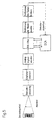
- the optoelectronic device 1 essentially consists of a transmission element 3, a receiving element 4 and an evaluation unit 5.
- the transmitting element 3 consists of a transmitter 6, preferably a laser diode, and from a transmitter optics 7 upstream of the transmitter 6 for focusing the Transmitted light 8.
- the focused transmitted light 8 is a deflection unit 9, the in the present embodiment of a rotating polygon mirror is formed, deflected and passed over the barcode symbol 2 to be detected.
- the axis of rotation of the polygon mirror wheel is perpendicular to that shown in FIG. 1 Equatorial plane of the polygon mirror wheel arranged.
- the reception light 10 reflected by the barcode symbol 2 is transmitted via the polygon mirror wheel led to the receiving element 4.
- the receiving element 4 exists from a photodiode 11, in which the received light 10 into an electronic received signal is converted, and one of these downstream amplifier 12. To improve the sensitivity of detection, the receiving element 4 a receiving optics 13 upstream.
- the received signal at the output of the receiving element 4 becomes the Evaluation unit 5 supplied.
- FIG. 3 shows the principle of evaluating the received signals.
- Figure 3a is a bar code symbol 2 with a sequence of black and white Line elements 2a, b shown. If the diameter of the transmitted light beam 8 on the barcode symbol 2 is significantly smaller than the smallest width of a line element 2a, b, the transmission light 8 is due to the reflection from the barcode symbol 2 as shown in Fig. 3b amplitude modulated.
- the curve shown in Fig. 3b corresponds to the Output of the receiving element 3 pending reception signal.
- the determination of the width of the individual line elements 2a, b of the barcode symbol 2 in the evaluation unit 5 expediently takes place according to the turning point method.
- the received signal is differentiated (Fig. 3c) the extremes of the differentiated received signal are determined, which correspond to the turning points of the received signal. These turning points again define the transitions from a black to a white line element 2a, b or vice versa.
- the differentiated received signal is preferably converted into a binary signal sequence (FIG. 3 d) with two switching thresholds S 1 and S 2 (FIG. 3 c).
- the duration of the states '0' and '1' of the binary signal sequence is a measure of the width of the line elements 2a, b of the barcode symbol 2.
- the duration of the states '0' and '1' can be easily recorded using a clock-controlled counter .
- a measure of the deviation of the received signal from the actual contrast pattern forms the so-called decoding security DS.
- a barcode symbol 2 can be from the device 1 be recognized with certainty.
- the decoding security becomes DS smaller.
- the component-related interference can or the diameter of the transmitted light beam 8 must be so large that line elements 2a, b of the barcode symbol 2 with different width ratios a receive signal with equidistant inflection points.
- line elements 2a, b of different widths can no longer be recognized become.
- a 10-bit analog-digital converter is used 15 used.
- the digital filter 16 is formed by a non-recursive FIR filter.
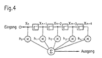
- the basic structure of an FIR filter is shown in FIG. 4.
- the variable z shown in FIG. 4 is the variable in the frequency domain conjugated to the time variable n.
- the size z -1 represents the amount of delay between two connection points, for example x n and x n-1 .
- the symbols x and ⁇ characterize a multiplicative or additive connection.
- the input variables x m are weighted with adjustable coefficients h m .
- the number of coefficients h m determines the degree of the filter.
- an FIR filter of the 18th degree is used.
- the digitized and filtered received signal becomes the threshold unit 14 fed and converted there into a binary signal sequence.
- the transfer function of the digital filter 16 is designed that signal distortion of the received signal caused by components or caused by the finite diameter of the transmitted light beam 8 can be eliminated.
- the influence of the transmit beam diameter 8 on the decoding security depends on the ratio of the diameter to the widths of the line elements 2a, b of the barcode symbol 2. Furthermore, the diameter of the Transmitting light beam 8 from the distance d between the bar code symbol 2 and the device 1 from. Finally, it affects the design of the signal-distorting components the size of the interference signals.
- the barcode reader is connected to a computer unit, not shown and detects the line elements at predetermined intervals d barcode symbols 2 2a, b with defined width ratios.
- This Received signal has signal distortion caused by the receiving element 4 and caused by the finite diameter of the transmitted light beam 8 become.
- the received signal not only contains information about the configuration of the barcode symbol 2 which was scanned, but also information via the transmitted light beam 8 and the receiving element 4.
- This received signal is digitized in the analog-digital converter 15, the FIR filter and finally fed to the computer unit.
- the contrast pattern of the Barcode symbol 2 stored in the computing unit.
- the positions of the turning points of the received signal are in the computer unit determined and with the positions of the transitions from black to white line elements 2a, b compared. The deviation of these positions becomes the Decoding security of the device 1 determined.
- the coefficients h m of the filter 16 are set to predetermined values which form the initial condition for the subsequent variation process.
- the value of one of the coefficients h m of the filter 16 is expediently set to 1 as the initial condition, while the remaining coefficients h m assume the value 0.
- the coefficient h m of the FIR filter is varied in the computer unit using the design centering analysis (DCA) method.
- DCA design centering analysis
- This process is repeated in several iteration steps, each time the decoding security of the previous iteration step determined in the computer unit is used for the current iteration step. The iteration is then canceled. if the decoding security has a predetermined setpoint exceeds.
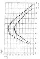
- the temporal change in the coefficients of the FIR filter is shown in FIG. 6 during the individual iteration steps.
- the optimization of the coefficients of the filter is not expedient only for a reading distance, but for a specified distance range performed, the setpoint for the decoding security for each reading distance must be achieved.
- the digital filter 16 can be dimensioned so that the Decoding security in a given reading distance range improved becomes.
- the results of such a variation are shown in Fig. 9 (upper curve).
- the coefficients of the digital filter 16 can thus be determined without that a real scan of the barcode symbol 2 needs to take place.
- the transfer function of the receiving element 4 in Overall model can be specified within a specified range can. This can influence the spread of specimens on decoding security be compensated.
- FIG. 7 shows an example of an optimized set of the coefficients h m of the digital filter 16.
- the coefficients are designed asymmetrically with respect to the center or the perpendicular.
- the asymmetrical component of the coefficients h m eliminates phase distortions in the received signal which are caused by the receiving element 4.
- the symmetrical component of the coefficients h m eliminates amplitude distortions of the received signal, which are caused by the finite diameter of the transmitted light beam 8 and the received element 4.
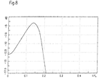
- FIG. 8 shows the transfer function of the digital filter 16 which results from the Fourier transform of the coefficients of the digital filter 16 according to FIG. 7.
- the frequency f a 10 MHz.
- the transfer function essentially corresponds to the inverse of the frequency spectrum the spatial distribution of the transmitted light beam 8, which is essentially has a Gaussian characteristic. Deviations from this stem from the signal distortions caused by the receiving element 4.
- the computer unit is separated from the device 1.
- the optimized coefficient set h m of the digital filter 16 is maintained during the operation of the device 1.
- a readjustment of the coefficients h m of the digital filter 16 and thus of the transfer function is not necessary in particular if the coefficients h m are optimized for different reading distances d and bar code symbols 2.
Abstract
Claims (16)
- Dispositif optoélectronique d'identification de marques pourvues de motifs de contraste définis, avec un élément d'émission émettant un rayon ou faisceau lumineux d'émission, et avec un élément récepteur, le faisceau lumineux d'émission étant déplacé au-dessus de la marque, et dans lequel le faisceau lumineux de réception, réfléchi par la marque, présente une modulation d'amplitude imprimée par le contraste de la marque et dépendante de la variation spatiale de l'intensité du rayon de lumière émis et dans lequel la lumière reçue est convertie dans l'élément récepteur en un signal de réception analogique, caractérisé en ce que le signal de réception analogique est converti en un signal de réception numérique dans un convertisseur analogique-numérique à n bits (15), dont la largeur de mot n est supérieure à un, et transféré vers un filtre numérique (16) dont la caractéristique de transmission correspond essentiellement à l'inverse du spectre fréquentiel de la répartition spatiale de l'intensité du rayon lumineux d'émission (8) à l'endroit de la marque.
- Dispositif selon la revendication 1, caractérisé en ce que la caractéristique de transmission du filtre numérique (16), au sein d'une marge de tolérance prédéfinie, correspond à l'inverse du spectre fréquentiel de la répartition spatiale de l'intensité du rayon lumineux de réception (10) pour un domaine prédéfini de la distance entre la marque et le dispositif (1).
- Dispositif selon la revendication 1 ou 2, caractérisé en ce que la caractéristique de transmission du filtre numérique (16) pour la compensation des perturbations du signal de réception, dues aux composants, présente des écarts définis par l'inverse du spectre fréquentiel de la répartition spatiale de l'intensité du faisceau lumineux d'émission (8) à l'endroit de la marque, qui correspondent aux fonctions d'inversion des fonctions de transmission des composants.
- Dispositif selon la revendication 3, caractérisé en ce que le composant produisant une distorsion du signal est constitué par le récepteur (4).
- Dispositif selon l'une des revendications 1 à 4, caractérisé en ce que le filtre numérique (16) est constitué par un filtre FIR aux coefficients réglables.
- Dispositif selon la revendication 5, caractérisé en ce que le filtre FIR est constitué par un filtre du 18ème degré.
- Dispositif selon l'une des revendications 1 à 6, caractérisé en ce que la largeur de mot du convertisseur analogique-numérique à n bits (15) est comprise entre 8 ≤ n ≤ 12.
- Dispositif selon l'une des revendications 1 à 7, caractérisé en ce qu'il est réalisé en tant que lecteur de codes-barres, dont l'élément d'émission (3) présente un émetteur (6) réalisé sous la forme d'un laser, dont le faisceau de lumière émise (8) est dévié par une unité de déflexion (9), et dont l'élément de réception (4) présente une photodiode (11) et un amplificateur (12) pour l'amplification du signal de réception.
- Procédé de réduction de distorsions de signaux pour dispositif optoélectronique (1) selon l'une quelconque des revendications précédentes, caractérisé en ce qu'il présente les étapes suivantes :Modélisation du système d'ensemble du dispositif optoélectronique (1) constitué du spectre fréquentiel de la répartition spatiale de l'intensité du faisceau lumineux d'émission (8) à l'endroit de la marque, ainsi que des fonctions de transmission des composants produisant une distorsion du signal, et du filtre numérique (16).Détermination expérimentale de la fiabilité de décodage du dispositif (1) en fonction de la distance de lecture d de la marque au dispositif (1) pour un certain préréglage du filtre numérique (16), cette fiabilité de décodage correspondant au degré de concordance de la modulation d'amplitude du signal de réception avec le motif de contraste de la marque.Variation des coefficients réglables du filtre numérique (16) pour une fonction de transmission donnée des composants produisant une distorsion du signal, et pour un spectre fréquentiel donné de la répartition spatiale de l'intensité du faisceau lumineux d'émission (8) à l'endroit de la marque, jusqu'à dépassement du seuil prédéfini de la fiabilité de décodage.
- Procédé selon la revendication 9, caractérisé en ce que l'on attribue, comme condition initiale, à l'un des coefficients du filtre numérique (16) la valeur un, et la valeur zéro à tous les coefficients restants.
- Procédé selon la revendication 9 ou 10, caractérisé en ce que la variation des coefficients a lieu selon le principe de conception centralisée.
- Procédé selon l'une des revendications 9 à 11, caractérisé en ce que la variation des coefficients du filtre numérique (16) a lieu pour une distance d entre la marque et le dispositif (1) prédéfinie et pour un motif de contraste prédéfini de la marque.
- Procédé selon l'une des revendications 9 à 11, caractérisé en ce que la variation des coefficients du filtre numérique (16) a lieu pour plusieurs distances d à l'intérieur d'un domaine prédéfini, et pour différents motifs de contraste des marques, jusqu'à dépassement d'un seuil prédéfini de la fiabilité de décodage pour chacune des distances et chacun des motifs de contraste.
- Procédé selon l'une des revendications 9 à 13, caractérisé en ce que la détermination des valeurs de la fiabilité de décodage a lieu au sein du dispositif (1).
- Procédé selon l'une des revendications 9 à 14, caractérisé en ce que la fonction de transmission des composants produisant une distorsion du signal est déterminée par voie expérimentale.
- Procédé selon l'une des revendications 9 à 15, caractérisé en ce que la fonction de transmission des composants produisant une distorsion du signal est prédéfinie à l'intérieur d'une largeur de bande prédéfinie appliquée au modèle du système d'ensemble, cette largeur de bande correspondant aux coefficients de dispersion unitaires des composants.
Applications Claiming Priority (3)
| Application Number | Priority Date | Filing Date | Title |
|---|---|---|---|
| DE4411023 | 1994-03-30 | ||
| DE4411023A DE4411023C2 (de) | 1994-03-30 | 1994-03-30 | Optoelektronische Vorrichtung zum Erkennen von Kontrastmarken und Verfahren zur Reduktion von Signalverzerrungen für eine optoelektronische Vorrichtung zum Erkennen von Kontrastmarken |
| PCT/EP1995/000893 WO1995027257A1 (fr) | 1994-03-30 | 1995-03-10 | Dispositif optoelectronique pour l'identification de marques de contraste |
Publications (2)
| Publication Number | Publication Date |
|---|---|
| EP0728340A1 EP0728340A1 (fr) | 1996-08-28 |
| EP0728340B1 true EP0728340B1 (fr) | 2001-06-27 |
Family
ID=6514228
Family Applications (1)
| Application Number | Title | Priority Date | Filing Date |
|---|---|---|---|
| EP95912238A Expired - Lifetime EP0728340B1 (fr) | 1994-03-30 | 1995-03-10 | Dispositif optoelectronique pour l'identification de marques de contraste |
Country Status (4)
| Country | Link |
|---|---|
| US (1) | US5675136A (fr) |
| EP (1) | EP0728340B1 (fr) |
| DE (2) | DE4411023C2 (fr) |
| WO (1) | WO1995027257A1 (fr) |
Cited By (1)
| Publication number | Priority date | Publication date | Assignee | Title |
|---|---|---|---|---|
| EP1217571B2 (fr) † | 2000-12-21 | 2014-03-12 | Datalogic IP TECH S.r.l. | Méthode et dispositif pour focaliser un signal électrique, représentant un code optique |
Families Citing this family (13)
| Publication number | Priority date | Publication date | Assignee | Title |
|---|---|---|---|---|
| US5761219A (en) * | 1996-07-12 | 1998-06-02 | Intermec Technologies Corporation | Error correction for PDF417 and other machine-readable symbologies |
| NL1008260C2 (nl) * | 1998-02-10 | 1999-08-11 | Scantech Bv | Optische inrichting voor het uitlezen en decoderen van een barcode. |
| US6405929B1 (en) | 1998-05-29 | 2002-06-18 | Hand Held Products, Inc. | Material detection systems for security documents |
| DE29815383U1 (de) * | 1998-08-27 | 1998-12-10 | Leuze Electronic Gmbh & Co | Optoelektronische Vorrichtung |
| US6561422B1 (en) * | 1999-05-03 | 2003-05-13 | Hewlett-Packard Development Company | System and method for high-contrast marking and reading |
| JP4364631B2 (ja) * | 2001-05-25 | 2009-11-18 | 株式会社オプトエレクトロニクス | 光学的情報読取装置 |
| JP4213490B2 (ja) * | 2003-02-21 | 2009-01-21 | 富士通株式会社 | バーコード読取装置 |
| US8316068B2 (en) | 2004-06-04 | 2012-11-20 | Telefonaktiebolaget Lm Ericsson (Publ) | Memory compression |
| US7128264B2 (en) * | 2004-07-23 | 2006-10-31 | Symbol Technologies, Inc: | Electro-optical reader with improved performance in high intensity ambient light |
| US7506816B2 (en) * | 2004-10-04 | 2009-03-24 | Datalogic Scanning, Inc. | System and method for determining a threshold for edge detection based on an undifferentiated equalized scan line signal |
| US20120118969A1 (en) * | 2010-11-11 | 2012-05-17 | Psion Teklogix Inc. | System and method for barcode scanning using image calibration |
| US9702707B2 (en) * | 2011-12-22 | 2017-07-11 | AppLabz, LLC | Systems, methods, and apparatus for providing indoor navigation using optical floor sensors |
| US10332287B2 (en) * | 2015-11-02 | 2019-06-25 | Rohde & Schwarz Gmbh & Co. Kg | Measuring device and method for visually presenting a signal parameter in a displayed signal |
Citations (2)
| Publication number | Priority date | Publication date | Assignee | Title |
|---|---|---|---|---|
| EP0433593A2 (fr) * | 1989-11-20 | 1991-06-26 | Symbol Technologies, Inc. | Lecteurs de codes à barres avec meilleure mise en contraste de contours |
| WO1995012861A1 (fr) * | 1993-11-05 | 1995-05-11 | Leuze Electronic Gmbh + Co. | Dispositif opto-electronique de reconnaissance de symboles de code a barres |
Family Cites Families (7)
| Publication number | Priority date | Publication date | Assignee | Title |
|---|---|---|---|---|
| US4323772A (en) * | 1980-03-06 | 1982-04-06 | R. J. Reynolds Tobacco Company | Bar code reader system |
| GB2143636A (en) * | 1983-07-22 | 1985-02-13 | Stephen Kenneth Buss | A circuit arrangement and method for detecting markers in a microfilm scanner |
| US4761544A (en) * | 1985-11-15 | 1988-08-02 | Hewlett-Packard Company | Means and method of scaling time interval measurements from an optical bar code scanner to improve decoder efficiency |
| US4998010A (en) * | 1988-04-08 | 1991-03-05 | United Parcel Service Of America, Inc. | Polygonal information encoding article, process and system |
| US5563955A (en) * | 1990-11-21 | 1996-10-08 | The Board Of Trustees Of The University Of Arkansas | Apparatus and/or method for recognizing printed data in an image |
| DE4208082C1 (en) * | 1992-03-13 | 1993-02-11 | Agfa-Gevaert Ag, 5090 Leverkusen, De | Reading bar=code on edge of photographic film - ascertaining code start and end and thus length by relative speed between film and sensor arrangement |
| JP3230612B2 (ja) * | 1992-09-02 | 2001-11-19 | オリンパス光学工業株式会社 | 2次元バーコードリーダ |
-
1994
- 1994-03-30 DE DE4411023A patent/DE4411023C2/de not_active Expired - Lifetime
- 1994-03-30 US US08/556,899 patent/US5675136A/en not_active Expired - Fee Related
-
1995
- 1995-03-10 WO PCT/EP1995/000893 patent/WO1995027257A1/fr active IP Right Grant
- 1995-03-10 DE DE59509364T patent/DE59509364D1/de not_active Expired - Fee Related
- 1995-03-10 EP EP95912238A patent/EP0728340B1/fr not_active Expired - Lifetime
Patent Citations (2)
| Publication number | Priority date | Publication date | Assignee | Title |
|---|---|---|---|---|
| EP0433593A2 (fr) * | 1989-11-20 | 1991-06-26 | Symbol Technologies, Inc. | Lecteurs de codes à barres avec meilleure mise en contraste de contours |
| WO1995012861A1 (fr) * | 1993-11-05 | 1995-05-11 | Leuze Electronic Gmbh + Co. | Dispositif opto-electronique de reconnaissance de symboles de code a barres |
Cited By (1)
| Publication number | Priority date | Publication date | Assignee | Title |
|---|---|---|---|---|
| EP1217571B2 (fr) † | 2000-12-21 | 2014-03-12 | Datalogic IP TECH S.r.l. | Méthode et dispositif pour focaliser un signal électrique, représentant un code optique |
Also Published As
| Publication number | Publication date |
|---|---|
| DE59509364D1 (de) | 2001-08-02 |
| EP0728340A1 (fr) | 1996-08-28 |
| DE4411023A1 (de) | 1995-10-05 |
| US5675136A (en) | 1997-10-07 |
| WO1995027257A1 (fr) | 1995-10-12 |
| DE4411023C2 (de) | 1996-04-04 |
Similar Documents
| Publication | Publication Date | Title |
|---|---|---|
| EP0728340B1 (fr) | Dispositif optoelectronique pour l'identification de marques de contraste | |
| DE4405376C1 (de) | Verfahren zum Erfassen von Objekten in einem Überwachungsbereich | |
| DE69534706T2 (de) | Abtastgerät mit variabler fleckgrösse | |
| DE19882768B3 (de) | Zweiter Ordnung differenzierender Signalprozessor für einen Strichkodescanner sowie Signalverarbeitungsverfahren zum Verwenden von Strichkodescannern | |
| EP1262906A2 (fr) | Procédé et dispositif de mesure de distance | |
| EP1921565B1 (fr) | Appareil de lecture d'un code à barres | |
| EP0720762B1 (fr) | Dispositif optoelectronique pour identifier des marques de contraste | |
| DE2922091C2 (de) | Verfahren zur Analog-Digital-Umwandlung von gestörten Analogsignalen | |
| EP0747727B1 (fr) | Méthode et dispositif de mesure de distance | |
| DE4013660A1 (de) | Verfahren und vorrichtung zur unterscheidung von kontinuierlichen schmalbandwellensignalen von breitbandsignalen und stossartigen signalen | |
| DE4323293C2 (de) | Verfahren und Abtastanordnung zur Identifizierung eines aus aufeinanderfolgenden hellen und dunklen Feldern bestehenden Codes | |
| DE4337718C1 (de) | Verfahren zur Kompensation bauteilbedingter Signalverzerrungen für eine optoelektronische Vorrichtung und optoelektronische Vorrichtung zum Erkennen von insbesondere Barcode-Symbolen | |
| DE3602008A1 (de) | Optische abtastvorrichtung mit einem spiegelrad | |
| EP0427969B1 (fr) | Dispositif de mesure du temps de vol d'une impulsion | |
| DE102019209653A1 (de) | Signalverarbeitungsverfahren für photoelektrischen Kodierer | |
| DE4105516C2 (de) | Verfahren und Vorrichtung zur verbesserten Wiedergabe von Konturen | |
| EP2735887B1 (fr) | Dispositif d'enregistrement optique | |
| EP0777130A2 (fr) | Procédé digital de détection d'impulsions courtes et appareil pour la mise en oeuvre du procédé | |
| EP2388934A1 (fr) | Procédé de correction de fronts d'ondes optiques déformés dans l'atmosphère | |
| DE19724711A1 (de) | Verfahren und Vorrichtung zum Erkennen und Lesen eines an einem Objekt vorgesehenen Strichcodes | |
| DE19537953C2 (de) | Optoelektronische Vorrichtung und Verfahren zum Erkennen von Barcode-Symbolen | |
| EP0660132A1 (fr) | Procédé numérique de détection d'une impulsion courte en temps et dispositif pour sa mise en oeuvre | |
| EP1131774B1 (fr) | Dispositif pour lire un code a barres | |
| EP2017653B1 (fr) | Capteur optoélectronique et procédé de réception doté d'un correcteur de lumière parasite | |
| DE69938521T2 (de) | Strichkodeleser mit einer Übergangsdetektorschaltung |
Legal Events
| Date | Code | Title | Description |
|---|---|---|---|
| PUAI | Public reference made under article 153(3) epc to a published international application that has entered the european phase |
Free format text: ORIGINAL CODE: 0009012 |
|
| 17P | Request for examination filed |
Effective date: 19950405 |
|
| AK | Designated contracting states |
Kind code of ref document: A1 Designated state(s): CH DE FR GB IT LI NL |
|
| 17Q | First examination report despatched |
Effective date: 19990510 |
|
| GRAG | Despatch of communication of intention to grant |
Free format text: ORIGINAL CODE: EPIDOS AGRA |
|
| GRAG | Despatch of communication of intention to grant |
Free format text: ORIGINAL CODE: EPIDOS AGRA |
|
| GRAH | Despatch of communication of intention to grant a patent |
Free format text: ORIGINAL CODE: EPIDOS IGRA |
|
| GRAH | Despatch of communication of intention to grant a patent |
Free format text: ORIGINAL CODE: EPIDOS IGRA |
|
| GRAA | (expected) grant |
Free format text: ORIGINAL CODE: 0009210 |
|
| AK | Designated contracting states |
Kind code of ref document: B1 Designated state(s): CH DE FR GB IT LI NL |
|
| REG | Reference to a national code |
Ref country code: CH Ref legal event code: EP |
|
| REG | Reference to a national code |
Ref country code: CH Ref legal event code: NV Representative=s name: ROTTMANN, ZIMMERMANN + PARTNER AG |
|
| REF | Corresponds to: |
Ref document number: 59509364 Country of ref document: DE Date of ref document: 20010802 |
|
| GBT | Gb: translation of ep patent filed (gb section 77(6)(a)/1977) |
Effective date: 20010824 |
|
| ITF | It: translation for a ep patent filed |
Owner name: MODIANO & ASSOCIATI S.R.L. |
|
| ET | Fr: translation filed | ||
| REG | Reference to a national code |
Ref country code: GB Ref legal event code: IF02 |
|
| PLBE | No opposition filed within time limit |
Free format text: ORIGINAL CODE: 0009261 |
|
| STAA | Information on the status of an ep patent application or granted ep patent |
Free format text: STATUS: NO OPPOSITION FILED WITHIN TIME LIMIT |
|
| 26N | No opposition filed | ||
| REG | Reference to a national code |
Ref country code: FR Ref legal event code: CJ Ref country code: FR Ref legal event code: CD |
|
| PGFP | Annual fee paid to national office [announced via postgrant information from national office to epo] |
Ref country code: DE Payment date: 20080403 Year of fee payment: 14 |
|
| PGFP | Annual fee paid to national office [announced via postgrant information from national office to epo] |
Ref country code: NL Payment date: 20090317 Year of fee payment: 15 |
|
| PGFP | Annual fee paid to national office [announced via postgrant information from national office to epo] |
Ref country code: GB Payment date: 20090325 Year of fee payment: 15 Ref country code: CH Payment date: 20090316 Year of fee payment: 15 |
|
| PGFP | Annual fee paid to national office [announced via postgrant information from national office to epo] |
Ref country code: IT Payment date: 20090325 Year of fee payment: 15 |
|
| PGFP | Annual fee paid to national office [announced via postgrant information from national office to epo] |
Ref country code: FR Payment date: 20090312 Year of fee payment: 15 |
|
| PG25 | Lapsed in a contracting state [announced via postgrant information from national office to epo] |
Ref country code: DE Free format text: LAPSE BECAUSE OF NON-PAYMENT OF DUE FEES Effective date: 20091001 |
|
| REG | Reference to a national code |
Ref country code: NL Ref legal event code: V1 Effective date: 20101001 |
|
| REG | Reference to a national code |
Ref country code: CH Ref legal event code: PL |
|
| GBPC | Gb: european patent ceased through non-payment of renewal fee |
Effective date: 20100310 |
|
| REG | Reference to a national code |
Ref country code: FR Ref legal event code: ST Effective date: 20101130 |
|
| PG25 | Lapsed in a contracting state [announced via postgrant information from national office to epo] |
Ref country code: NL Free format text: LAPSE BECAUSE OF NON-PAYMENT OF DUE FEES Effective date: 20101001 Ref country code: FR Free format text: LAPSE BECAUSE OF NON-PAYMENT OF DUE FEES Effective date: 20100331 |
|
| PG25 | Lapsed in a contracting state [announced via postgrant information from national office to epo] |
Ref country code: LI Free format text: LAPSE BECAUSE OF NON-PAYMENT OF DUE FEES Effective date: 20100331 Ref country code: CH Free format text: LAPSE BECAUSE OF NON-PAYMENT OF DUE FEES Effective date: 20100331 |
|
| PG25 | Lapsed in a contracting state [announced via postgrant information from national office to epo] |
Ref country code: IT Free format text: LAPSE BECAUSE OF NON-PAYMENT OF DUE FEES Effective date: 20100310 Ref country code: GB Free format text: LAPSE BECAUSE OF NON-PAYMENT OF DUE FEES Effective date: 20100310 |