EP0427969B1 - Dispositif de mesure du temps de vol d'une impulsion - Google Patents
Dispositif de mesure du temps de vol d'une impulsion Download PDFInfo
- Publication number
- EP0427969B1 EP0427969B1 EP90119867A EP90119867A EP0427969B1 EP 0427969 B1 EP0427969 B1 EP 0427969B1 EP 90119867 A EP90119867 A EP 90119867A EP 90119867 A EP90119867 A EP 90119867A EP 0427969 B1 EP0427969 B1 EP 0427969B1
- Authority
- EP
- European Patent Office
- Prior art keywords
- pulse
- transit time
- digital converter
- measuring arrangement
- time measuring
- Prior art date
- Legal status (The legal status is an assumption and is not a legal conclusion. Google has not performed a legal analysis and makes no representation as to the accuracy of the status listed.)
- Expired - Lifetime
Links
Images


Classifications
-
- G—PHYSICS
- G01—MEASURING; TESTING
- G01S—RADIO DIRECTION-FINDING; RADIO NAVIGATION; DETERMINING DISTANCE OR VELOCITY BY USE OF RADIO WAVES; LOCATING OR PRESENCE-DETECTING BY USE OF THE REFLECTION OR RERADIATION OF RADIO WAVES; ANALOGOUS ARRANGEMENTS USING OTHER WAVES
- G01S13/00—Systems using the reflection or reradiation of radio waves, e.g. radar systems; Analogous systems using reflection or reradiation of waves whose nature or wavelength is irrelevant or unspecified
- G01S13/02—Systems using reflection of radio waves, e.g. primary radar systems; Analogous systems
- G01S13/06—Systems determining position data of a target
- G01S13/08—Systems for measuring distance only
- G01S13/10—Systems for measuring distance only using transmission of interrupted, pulse modulated waves
- G01S13/103—Systems for measuring distance only using transmission of interrupted, pulse modulated waves particularities of the measurement of the distance
-
- G—PHYSICS
- G01—MEASURING; TESTING
- G01S—RADIO DIRECTION-FINDING; RADIO NAVIGATION; DETERMINING DISTANCE OR VELOCITY BY USE OF RADIO WAVES; LOCATING OR PRESENCE-DETECTING BY USE OF THE REFLECTION OR RERADIATION OF RADIO WAVES; ANALOGOUS ARRANGEMENTS USING OTHER WAVES
- G01S17/00—Systems using the reflection or reradiation of electromagnetic waves other than radio waves, e.g. lidar systems
- G01S17/02—Systems using the reflection of electromagnetic waves other than radio waves
- G01S17/06—Systems determining position data of a target
- G01S17/08—Systems determining position data of a target for measuring distance only
- G01S17/10—Systems determining position data of a target for measuring distance only using transmission of interrupted, pulse-modulated waves
Definitions
- the invention relates to a pulse transit time measuring arrangement according to the preamble of claim 1.
- Such a pulse transit time measuring arrangement is known from DE-A 36 20 226. It is particularly suitable for laser range finders with low transmission pulse energy for measurements on distant, small, weakly reflecting objects.
- the received pulses are very weak and are sometimes smaller than noise signals occurring in the arrangement.
- the analog-to-digital converter and the parallel adder can therefore be designed with a small number of bits, as a result of which the necessary processing speed can be easily achieved and the circuit complexity is kept low.
- the analog-digital converter is overdriven or, after a few added pulses, the parallel adder is overdriven. The result of this is that the maximum value of the respective output signal is reached over several sampling pulse intervals. The determination of the peak position is thereby undetermined.
- a differentiator is continuously switched on in the digital processing of received pulses.
- delta modulation Something similar is known as delta modulation and is used, for example, in the field of speech recognition.
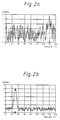
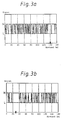
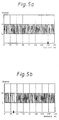
- Figures 2 through 6 are the result of computer simulations.
- FIGS. 3 to 6 impulses of predetermined shape and amplitude with statistical noise predetermined average amplitude were superimposed and the processing steps described below for FIGS. 3 to 6 were simulated. This serves to make it easier to understand and takes into account the difficulty in deriving the very fast low-energy signals from the complex arrangement without interference.
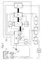
- the light pulse transmitter 1 first shows a light pulse transmitter 1, a light reflecting object 2 and a light receiver 3, which form an optical pulse transit time measuring section.
- the light pulse transmitter 1 consists, for. B. from a GaAs laser diode with power supply, pulse shaping in the nanosecond range and stabilization.
- Object 2 is shown as a triple mirror, i.e. as a cooperative element.
- the invention finds particularly advantageous application in any diffusely reflecting objects, such as machine parts, buildings, etc.
- Light pulse transmitter 1 and light receiver 3 generally also contain optics for determining a suitable geometry of the transmitted and received light bundles.
- a capacitor 4 suppresses constant light components by capacitive signal coupling.
- an electrical signal which contains the transit time and intensity of the received light pulse and an independent noise component.
- the signal is fed to an n-bit analog-digital converter 6 via an amplifier 5.
- the analog-digital converter 6 preferably has a low number of bits, in particular only 1 bit.
- the digital signal B from the output of the analog-digital converter 6 is fed to a parallel adder 7.
- a trigger pulse generator 8 with a pulse rate in the kilohertz range controls the light pulse transmitter 1, the parallel adder 7 and an evaluation circuit 10, which will be described below.
- a sampling pulse generator 9 with a pulse rate in the megahertz range generates the operating clock of the analog-digital converter 6 and the parallel adder 7 and gives the time standard for the evaluation circuit 10.
- the parallel adder 7 has a number of channels which is sufficient to fully capture the receive pulse for the largest and smallest range of the arrangement.
- the number of channels is therefore greater than the product of the greatest transit time and frequency of the sampling pulse generator 9.
- the evaluation device 10 determines from the data field C at the output of the parallel adder 7 the transit time of the light pulse or the distance between the receiver 3 and object 2 and forwards this to a measured value display 12, a measured value memory 13 and / or a processing device 14.
- the evaluation device 10 can easily determine the pulse transit time from the channel with the maximum signal amplitude.
- the correlation with a target data field for the pulse shape is preferred.
- interpolation with a suitable information function reflecting the expected pulse shape can also be used.
- a device 11 is provided for making this target data field available. This can be digital storage.
- the device 11 can, however, also be connected via a transmitter 15 to a light pulse transmitter 1 and derive a desired data field from a transmission pulse for each measurement.
- the transmitter 15 can consist of a short light guide and a device corresponding to the parts 3, 4, 5 and 6.
- Figures 2a, 3a and 4a show that with a large measuring distance, in particular in the case of non-cooperative targets, received signals occurring at point A in FIG. 1 with a poor signal / noise ratio (FIG. 2a) at point C at the output of the Parallel adder 7 (Fig. 4a) can be significantly improved, although this does not look like this after the analog-digital converter 6 at point B in Fig. 1 (Fig. 3a).
- FIG. 2a signal / noise ratio
- Figures 2b, 3b and 4b each show the same as Figures 2a, 3a and 4a, but for received signals with a high signal-to-noise ratio, such as occur with a short measuring distance.
- a high signal-to-noise ratio such as occur with a short measuring distance.
- an overflow and a deterioration in the position determination of the maximum then occur due to the limited number of bits.
- the arrangement is expanded by a logic element 20 and a differentiating element 21.
- Both elements 20, 21 are connected between the capacitor 4 and the analog-digital converter 6, preferably in front of the amplifier 5.
- the logic element 20 is a self-holding threshold switch which, as long as the received signal at point A does not exceed a certain threshold value, switches a direct connection from point A to amplifier 5, as a result of which the entire arrangement functions as described above. If the threshold value is exceeded, the logic element 20 switches the differentiating element 21 into the signal line from point A to amplifier 5 and maintains this switching state. The effect achieved thereby is shown in FIGS. 5a / b and 6a / b.
- the signal curve of FIG. 5b results at position B after the analog-digital converter 6 instead of the signal curve of FIG. 3b.
- FIG. 6b results.
- the action of the differentiating element 21 has turned the maximum of the input signal A (FIG. 2b) into a steep passage through the mean value of the noise, the position of which can be determined very precisely.
- the differentiating element 21 must, however, be switched off again from the signal processing by the logic element 20 if the input signal has only a small amplitude at a great distance.
- the input signal of FIG. 2a leads with the differentiator 21 switched on to the signal curves of FIG. 5a at point B after the analog-digital converter 6 and of FIG. 6a at point C after the parallel adder 7.
- the combination of the logic element 20 with the differentiating element 21 introduced according to the invention thus has the effect that both large and small input signals are optimally evaluated.
- the evaluation device 10 Compared to the known design, the evaluation device 10 must be designed such that, when the differentiating element 21 is switched on, it determines the channel in which there is a basic level corresponding to the mean value of the noise between two extremes of the signal C summed in the parallel adder 7, different from the noise. If the evaluation device 10 works according to a correlation method or with interpolation, nothing needs to be changed or switched over to it, only the device 11 must provide a target data field corresponding to a differentiated signal or such an interpolation function.
- the evaluation device 10 or the device 11 is switched over by the logic element 20 simultaneously with the switching of the differentiating element 21.
- the dynamic range of the analog-digital converter 6 is advantageously designed so that it is greater than the mean value of the noise at its input (point A, Fig. 1), and that the digitization step size is so large that the noise in statistical mean half results in the value zero of the output signal.
- the mean value of the noise in the output signal is 0.5.
- the threshold value of the logic element 20 is set for optimal use of the two signal evaluation methods with and without differentiation at a signal amplitude that is in the range of two to ten times the mean amplitude of the noise (at point C).
- the number of bits in the analog-digital converter 6 must be taken into account.
- the analog-digital converter 6 can be connected to the logic element 20 and have an additional n + 1 bit, which is not passed on to the parallel adder 7, and when the input signal sets it, the logic element 20 the differentiator 21 turns on.
- the differentiating element 21 can simply be designed as an RC element at the input of the amplifier 5, as a result of which a differentiating amplifier is formed.
- the differentiator 21 does not need to perform exact differentiation since the signal from the analog-digital converter 6 is broken down into only a few bits.
- the logic element 20 also switches the sampling pulse generator 9 to an increased pulse rate simultaneously with the switching on of the differentiating element 21.
- the parallel adder 7 with a certain number of channels is thus well used for the light pulses with a short transit time by stretching the time scale (transit time per channel), so that a further improvement in the measurement accuracy is achieved.
- the holding period for a switching state of the logic element 20 can be set as a fixed value, e.g. B. for the duration of 50 light pulses. It is more advantageous if the evaluation device 10 continuously evaluates the output signal of the parallel adder 7 and determines a measure of the uncertainty of the transit time or distance value caused by the noise and compares this measure with an intended target value. If the value falls below this target value, the measured value is output to the measured value display 12, the measured value memory 13 and / or the processing device 14.
- the parallel adder 7 is reset to zero and the held switching state of the logic element 20 is released, so that the next input signal pulse is compared again with the threshold value.
- the measuring arrangement can be constructed in various technologies with conventional components, with the greatest possible integration being advantageous.
- amplifiers 5 OP
- Analog-digital converter 6 parallel adders 7 and pulse generators 8.9 as IC's commercially available. You only have to pay attention to the suitability for the required high frequencies (approx. 100 MHz).
- a microprocessor 22 of suitable clock frequency is preferably programmed such that it contains all elements 5 to 11 and 20, 21, that is to say, apart from transmitter 1 and receiver 3 and measured value display 12 etc., the entire core of the pulse transit time measuring arrangement.
- the transit time of the light pulses from transmitter 1 via object 2 to receiver 3 specifies the necessary time scale for data processing.
Claims (10)
- Dispositif de mesure du temps de parcours d'une impulsion comprenant- un émetteur d'impulsions de lumière (1)- un récepteur (3) et un amplificateur (5),- un convertisseur analogique-numérique (6),- un additionneur parallèle (7) ayant une pluralité de canaux et- un générateur d'impulsions de déclenchement pour impulsions de déclenchement et- un générateur d'impulsions de balayage (9)caractérisé par- un élément de différenciation (21) et- un élément logique (20) ayant une entrée qui est montée en parallèle à l'entrée du convertisseur analogique-numérique (6) et qui, lorsque l'amplitude du signal à l'entrée atteint une valeur prédéterminée, met en service l'élément de différentiation (21) entre le récepteur (3) et le convertisseur analogique-numérique(6) et maintient cet état de commutation pendant la durée d'une pluralité d'impulsions de déclenchement.
- Dispositif de mesure du temps de parcours d'une impulsion selon la revendication 1, caractérisé en ce que- l'émetteur d'impulsions de lumière (1) et le récepteur (3) fonctionnent avec des signaux optiques d'une durée dans la gamme des nanosecondes.- le générateur d'impulsions de déclenchement (8) produit une fréquence d'impulsions dans la gamme des kilohertz et- le générateur d'impulsions de balayage (9) produit une fréquence d'impulsions dans la gamme des megahertz.
- Dispositif de mesure de la durée de parcours d'impulsions selon la revendication 1, caractérisé en ce que
le générateur d'impulsions de balayage (9) produit deux fréquences d'impulsions différentes, une fréquence d'impulsions procurant un intervalle de balayage qui correspond approximativement à la demi-largeur de l'impulsion de signal de l'émetteur (1) et la seconde fréquence d'impulsions procurant un intervalle de balayage qui est au maximum la moitié, la seconde fréquence d'impulsions étant appliquée ensuite au convertisseur analogique-numérique (6) et à l'additionneur parallèle (7) lorsque l'élément différenciateur (21) est mis en service. - Dispositif de mesure de la durée de parcours d'une impulsion selon la revendication 1, caractérisé en ce que la zone dynamique du convertisseur analogique-numérique (6) est dimensionné de façon qu'elle soit supérieure à la valeur moyenne de la quantité de bruit à son entrée, et que la largeur de pas de numérisation du convertisseur analogique/numérique (6) est dimensionné de telle façon que le bruit à son entrée donne comme moyenne statistique à moitié la valeur zéro du signal de sortie.
- Dispositif de mesure de la durée de parcours d'une impulsion selon la revendication 1, caractérisé en ce qu'un dispositif d'exploitation (10) est prévu qui exploite le contenu de l'additionneur parallèle (7), en déterminant le canal dans lequel se trouve le maximum d'une impulsion obtenue par sommation dans l'additionneur parallèle (7) lorsque l'élément différenciateur (21) n'est pas mis en service, et
en déterminant la canal dans lequel est présent un niveau de base correspondant à la valeur moyenne du bruit entre deux valeurs extrêmes différentes du bruit d'un signal de sommation dans l'additionneur parallèle (7) lorsque l'élément de différentiation (21) est mis en service. - Dispositif de mesure de la durée du temps de parcours d'une impulsion selon la revendication 5, caractérisé en ce que le dispositif d'exploitation (10) exploite le contenu de l'additionneur parallèle (7) selon un procédé de corrélation.
- Dispositif de mesure de la durée de parcours d'une impulsion selon la revendication 5, caractérisé en ce que le dispositif d'exploitation (10) exploite le contenu de l'additionneur parallèle (7) selon un procédé d'interpollation.
- Dispositif de mesure de la durée de parcours d'une impulsion selon l'une des revendications 5, 6 ou 7, caractérisé en ce que le dispositif d'exploitation (10) associe le canal déterminé à une durée de temps de parcours de l'émetteur d'impulsions de lumière (1) par l'intermédiaire de l'objet (2) au récepteur (3), ainsi qu'à la distance entre l'objet réfléchissant (2) et le récepteur (3) et amène la durée de temps de parcours et/ou la distance d'un affichage (12) à un dispositif de stockage (13) où à un dispositif de traitement (14).
- Dispositif de mesure de la durée de parcours d'une impulsion selon la revendication 5, caractérisé en ce que le dispositif d'exploitation (10) produit pour le canal déterminé une mesure ou un degré pour l'insécurité occasionnée par le bruit et fait une comparaison de la valeur réelle de cette mesure de l'insécurité avec une valeur de consigne prédéterminée et transmet lors d'un passage en dessous de la valeur de consigne le canal déterminé comme valeur de mesure à un affichage de valeur de mesure (12), un dispositif de stockage de valeur de mesure (13) et/ou un dispositif de traitement (14), commute également l'additionneur parallèle 7 à zéro et libère l'état de commutation auparavant maintenu de l'élément logique (20).
- Dispositif de mesure de la durée de parcours d'impulsion selon la revendication 1, caractérisé en ce que le convertisseur analogique-numérique (6) comporte un plus grand nombre de chiffres binaires qu'il transmet à l'additionneur parallèle (7) et que les chiffres binaires restants sont amenés à l'élément logique (20).
Applications Claiming Priority (2)
| Application Number | Priority Date | Filing Date | Title |
|---|---|---|---|
| DE3937787A DE3937787C1 (fr) | 1989-11-14 | 1989-11-14 | |
| DE3937787 | 1989-11-14 |
Publications (3)
| Publication Number | Publication Date |
|---|---|
| EP0427969A2 EP0427969A2 (fr) | 1991-05-22 |
| EP0427969A3 EP0427969A3 (en) | 1992-08-19 |
| EP0427969B1 true EP0427969B1 (fr) | 1995-04-26 |
Family
ID=6393465
Family Applications (1)
| Application Number | Title | Priority Date | Filing Date |
|---|---|---|---|
| EP90119867A Expired - Lifetime EP0427969B1 (fr) | 1989-11-14 | 1990-10-17 | Dispositif de mesure du temps de vol d'une impulsion |
Country Status (5)
| Country | Link |
|---|---|
| US (1) | US5102220A (fr) |
| EP (1) | EP0427969B1 (fr) |
| JP (1) | JP2955007B2 (fr) |
| AT (1) | ATE121847T1 (fr) |
| DE (2) | DE3937787C1 (fr) |
Families Citing this family (13)
| Publication number | Priority date | Publication date | Assignee | Title |
|---|---|---|---|---|
| US5179286A (en) * | 1990-10-05 | 1993-01-12 | Mitsubishi Denki K.K. | Distance measuring apparatus receiving echo light pulses |
| US5345168A (en) * | 1993-02-01 | 1994-09-06 | The United States Of America As Represented By The Administrator Of The National Aeronautics And Space Administration | Burst-by-burst laser frequency monitor |
| US5453932A (en) * | 1994-01-12 | 1995-09-26 | Advanced Grade Technology, Inc. | Device and method for detecting and elimination of spurious ultrasonic ranging echoes |
| JP3138618B2 (ja) * | 1995-07-31 | 2001-02-26 | 三菱電機株式会社 | 車両用距離測定装置 |
| DE19644791C2 (de) * | 1996-10-28 | 2002-11-28 | Sick Ag | Verfahren und Vorrichtung zur Bestimmung der Lichtlaufzeit über eine zwischen einer Meßvorrichtung und einem reflektierenden Objekt angeordnete Meßstrecke |
| DE19704220A1 (de) * | 1997-02-05 | 1998-08-06 | Ingbuero Spies | Verfahren und Vorrichtung zum Bestimmen eines Abstandes zwischen Fahrzeug und Hindernis |
| US7179289B2 (en) * | 1998-03-30 | 2007-02-20 | Conor Medsystems, Inc. | Expandable medical device for delivery of beneficial agent |
| DE10112833C1 (de) * | 2001-03-16 | 2003-03-13 | Hilti Ag | Verfahren und Einrichtung zur elektrooptischen Distanzmessung |
| JP4037774B2 (ja) * | 2003-02-19 | 2008-01-23 | 富士通テン株式会社 | レーダ装置 |
| WO2007004606A1 (fr) | 2005-07-04 | 2007-01-11 | Nikon Vision Co., Ltd. | Appareil de mesure de distance |
| DE102007013714A1 (de) * | 2007-03-22 | 2008-10-02 | Sick Ag | Optoelektronischer Sensor und Verfahren zur Messung einer Entfernung oder einer Entfernungsänderung |
| US8170087B2 (en) * | 2007-05-10 | 2012-05-01 | Texas Instruments Incorporated | Correlation coprocessor |
| CN106019923B (zh) * | 2016-05-18 | 2018-11-13 | 中国科学技术大学 | 一种基于fpga的时间数字变换器 |
Family Cites Families (10)
| Publication number | Priority date | Publication date | Assignee | Title |
|---|---|---|---|---|
| US3164661A (en) * | 1961-08-22 | 1965-01-05 | Gen Precision Inc | Distance measuring system by irradiating a target with light and sensing the reflected light |
| US3503680A (en) * | 1967-03-31 | 1970-03-31 | Perkin Elmer Corp | Range measuring system |
| US3710384A (en) * | 1969-11-17 | 1973-01-09 | North American Rockwell | Signal-correlating apparatus for improving the angular resolution of a directionally ranging system |
| DE2229887C3 (de) * | 1972-06-19 | 1980-07-17 | Siemens Ag, 1000 Berlin Und 8000 Muenchen | Entfernungsmeßgerät mit einem als Sender arbeitenden Laser und seine Anwendung zur Geschwindigkeitsmessung |
| JPS5912145B2 (ja) * | 1977-10-21 | 1984-03-21 | 古野電気株式会社 | レ−ダ−及び類似装置 |
| JPS5828554B2 (ja) * | 1978-11-22 | 1983-06-16 | 松下電器産業株式会社 | 超音波距離計 |
| JPS58180970A (ja) * | 1982-04-16 | 1983-10-22 | Mitsubishi Electric Corp | 測距装置 |
| JPS61102506A (ja) * | 1984-10-25 | 1986-05-21 | Hitachi Metals Ltd | 微小寸法測定装置 |
| CH670895A5 (fr) * | 1985-12-31 | 1989-07-14 | Wild Heerbrugg Ag | |
| DE3640449C1 (de) * | 1986-11-27 | 1988-06-30 | Messerschmitt Boelkow Blohm | Einrichtung zum Bestimmen der Entfernung zwischen zwei Objekten,insbesondere zwei Kraftfahrzeugen |
-
1989
- 1989-11-14 DE DE3937787A patent/DE3937787C1/de not_active Expired - Lifetime
-
1990
- 1990-10-17 EP EP90119867A patent/EP0427969B1/fr not_active Expired - Lifetime
- 1990-10-17 AT AT90119867T patent/ATE121847T1/de not_active IP Right Cessation
- 1990-10-17 DE DE59008963T patent/DE59008963D1/de not_active Expired - Fee Related
- 1990-11-06 US US07/609,749 patent/US5102220A/en not_active Expired - Lifetime
- 1990-11-14 JP JP2308400A patent/JP2955007B2/ja not_active Expired - Lifetime
Also Published As
| Publication number | Publication date |
|---|---|
| DE59008963D1 (de) | 1995-06-01 |
| EP0427969A2 (fr) | 1991-05-22 |
| JPH03172790A (ja) | 1991-07-26 |
| DE3937787C1 (fr) | 1991-05-02 |
| US5102220A (en) | 1992-04-07 |
| JP2955007B2 (ja) | 1999-10-04 |
| EP0427969A3 (en) | 1992-08-19 |
| ATE121847T1 (de) | 1995-05-15 |
Similar Documents
| Publication | Publication Date | Title |
|---|---|---|
| DE4133196C2 (de) | Entfernungsmessvorrichtung | |
| EP1423731B1 (fr) | Procede et dispositif pour acquerir une image telemetrique tridimensionnelle | |
| DE69934142T2 (de) | Determination der zeitverzögerung und determination der signalverschiebung | |
| EP0427969B1 (fr) | Dispositif de mesure du temps de vol d'une impulsion | |
| DE4218303C1 (de) | Verfahren und Anordnung zur Abstandsmessung nach dem Impulslaufzeitprinzip | |
| EP0854368A2 (fr) | Senseur luminex employant une évalution du temps de vol de lumière | |
| EP3683599B1 (fr) | Procédé et dispositif de mesure de distance optique | |
| EP2870438B1 (fr) | Procédé et dispositif pour la détermination basée sur laser du niveau de remplissage d'une matière de remplissage dans un récipient | |
| DE3408404C2 (de) | Vorrichtung zur Radarsimulation | |
| EP2315053B1 (fr) | Dispositifs et procédé de mesure des moments de réception d'impulsions | |
| DE10232878A1 (de) | Vorrichtung und Verfahren zur Distanzmessung | |
| EP2140286B1 (fr) | Dispositif et procédé de mesure de l'instant de réception d'une impulsion | |
| CH670895A5 (fr) | ||
| WO1996012203A1 (fr) | Procede et dispositif de mesure electro-optique de distance | |
| DE2737467C2 (de) | Fernsteueranordnung | |
| DE10259283B4 (de) | Impulsradarvorrichtung | |
| DE602005005408T2 (de) | Verfahren und Vorrichtung zur Messung des Frequenzantworts eines digitalen Empfängers | |
| DE2845164A1 (de) | Ziel-ortungs- und entfernungs- messystem | |
| EP2490045A1 (fr) | Capteur optoélectronique et procédé destiné à la détection d'objets | |
| DE1616266B1 (de) | Vorrichtung zur Zeit- und Amplituden-Quantisierung von Radar-Videosignalen | |
| DE19805207C2 (de) | Verfahren zur Bestimmung einer Bewegungsrichtung | |
| DE102008020035B4 (de) | Verfahren und Schaltung zur Abstandsmessung nach dem Radarprinzip | |
| DE1763897A1 (de) | Geraet zur erkennung von impulsfolgen, insbesondere fuer ein impuls-doppler-radar | |
| DE4323553A1 (de) | Verfahren und Vorrichtung zur Signalverarbeitung | |
| DE3332634A1 (de) | Schaltungsanordnung zur entdeckung bewegter ziele in radarempfaengern |
Legal Events
| Date | Code | Title | Description |
|---|---|---|---|
| PUAI | Public reference made under article 153(3) epc to a published international application that has entered the european phase |
Free format text: ORIGINAL CODE: 0009012 |
|
| AK | Designated contracting states |
Kind code of ref document: A2 Designated state(s): AT CH DE FR GB IT LI SE |
|
| PUAL | Search report despatched |
Free format text: ORIGINAL CODE: 0009013 |
|
| AK | Designated contracting states |
Kind code of ref document: A3 Designated state(s): AT CH DE FR GB IT LI SE |
|
| 17P | Request for examination filed |
Effective date: 19920908 |
|
| RAP1 | Party data changed (applicant data changed or rights of an application transferred) |
Owner name: LEICA AG |
|
| 17Q | First examination report despatched |
Effective date: 19941012 |
|
| GRAA | (expected) grant |
Free format text: ORIGINAL CODE: 0009210 |
|
| AK | Designated contracting states |
Kind code of ref document: B1 Designated state(s): AT CH DE FR GB IT LI SE |
|
| REF | Corresponds to: |
Ref document number: 121847 Country of ref document: AT Date of ref document: 19950515 Kind code of ref document: T |
|
| ITF | It: translation for a ep patent filed |
Owner name: JACOBACCI & PERANI S.P.A. |
|
| REF | Corresponds to: |
Ref document number: 59008963 Country of ref document: DE Date of ref document: 19950601 |
|
| GBT | Gb: translation of ep patent filed (gb section 77(6)(a)/1977) |
Effective date: 19950515 |
|
| ET | Fr: translation filed | ||
| PLBE | No opposition filed within time limit |
Free format text: ORIGINAL CODE: 0009261 |
|
| STAA | Information on the status of an ep patent application or granted ep patent |
Free format text: STATUS: NO OPPOSITION FILED WITHIN TIME LIMIT |
|
| 26N | No opposition filed | ||
| REG | Reference to a national code |
Ref country code: CH Ref legal event code: PFA Free format text: LEICA AG TRANSFER- LEICA GEOSYSTEMS AG |
|
| REG | Reference to a national code |
Ref country code: GB Ref legal event code: IF02 |
|
| PGFP | Annual fee paid to national office [announced via postgrant information from national office to epo] |
Ref country code: DE Payment date: 20081022 Year of fee payment: 19 Ref country code: CH Payment date: 20081015 Year of fee payment: 19 |
|
| PGFP | Annual fee paid to national office [announced via postgrant information from national office to epo] |
Ref country code: AT Payment date: 20081015 Year of fee payment: 19 |
|
| PGFP | Annual fee paid to national office [announced via postgrant information from national office to epo] |
Ref country code: SE Payment date: 20081014 Year of fee payment: 19 Ref country code: IT Payment date: 20081025 Year of fee payment: 19 |
|
| PGFP | Annual fee paid to national office [announced via postgrant information from national office to epo] |
Ref country code: FR Payment date: 20081014 Year of fee payment: 19 |
|
| PGFP | Annual fee paid to national office [announced via postgrant information from national office to epo] |
Ref country code: GB Payment date: 20081021 Year of fee payment: 19 |
|
| REG | Reference to a national code |
Ref country code: CH Ref legal event code: PL |
|
| EUG | Se: european patent has lapsed | ||
| REG | Reference to a national code |
Ref country code: FR Ref legal event code: ST Effective date: 20100630 |
|
| PG25 | Lapsed in a contracting state [announced via postgrant information from national office to epo] |
Ref country code: FR Free format text: LAPSE BECAUSE OF NON-PAYMENT OF DUE FEES Effective date: 20091102 Ref country code: DE Free format text: LAPSE BECAUSE OF NON-PAYMENT OF DUE FEES Effective date: 20100501 |
|
| PG25 | Lapsed in a contracting state [announced via postgrant information from national office to epo] |
Ref country code: AT Free format text: LAPSE BECAUSE OF NON-PAYMENT OF DUE FEES Effective date: 20091017 |
|
| PG25 | Lapsed in a contracting state [announced via postgrant information from national office to epo] |
Ref country code: LI Free format text: LAPSE BECAUSE OF NON-PAYMENT OF DUE FEES Effective date: 20091031 Ref country code: CH Free format text: LAPSE BECAUSE OF NON-PAYMENT OF DUE FEES Effective date: 20091031 |
|
| PG25 | Lapsed in a contracting state [announced via postgrant information from national office to epo] |
Ref country code: GB Free format text: LAPSE BECAUSE OF NON-PAYMENT OF DUE FEES Effective date: 20091017 |
|
| PG25 | Lapsed in a contracting state [announced via postgrant information from national office to epo] |
Ref country code: IT Free format text: LAPSE BECAUSE OF NON-PAYMENT OF DUE FEES Effective date: 20091017 |
|
| PG25 | Lapsed in a contracting state [announced via postgrant information from national office to epo] |
Ref country code: SE Free format text: LAPSE BECAUSE OF NON-PAYMENT OF DUE FEES Effective date: 20091018 |