EP2870438B1 - Procédé et dispositif pour la détermination basée sur laser du niveau de remplissage d'une matière de remplissage dans un récipient - Google Patents
Procédé et dispositif pour la détermination basée sur laser du niveau de remplissage d'une matière de remplissage dans un récipient Download PDFInfo
- Publication number
- EP2870438B1 EP2870438B1 EP13729299.1A EP13729299A EP2870438B1 EP 2870438 B1 EP2870438 B1 EP 2870438B1 EP 13729299 A EP13729299 A EP 13729299A EP 2870438 B1 EP2870438 B1 EP 2870438B1
- Authority
- EP
- European Patent Office
- Prior art keywords
- frequency
- pulse
- scan
- laser
- laser pulses
- Prior art date
- Legal status (The legal status is an assumption and is not a legal conclusion. Google has not performed a legal analysis and makes no representation as to the accuracy of the status listed.)
- Active
Links
- 238000000034 method Methods 0.000 title claims description 45
- 239000000463 material Substances 0.000 title description 16
- 230000005540 biological transmission Effects 0.000 claims description 36
- 238000005516 engineering process Methods 0.000 claims description 15
- 238000011156 evaluation Methods 0.000 claims description 14
- 230000007274 generation of a signal involved in cell-cell signaling Effects 0.000 claims description 6
- 230000001105 regulatory effect Effects 0.000 claims description 6
- 238000005070 sampling Methods 0.000 description 64
- 238000005259 measurement Methods 0.000 description 59
- 238000010304 firing Methods 0.000 description 8
- 239000007788 liquid Substances 0.000 description 8
- 238000010586 diagram Methods 0.000 description 4
- 230000001419 dependent effect Effects 0.000 description 3
- 230000000737 periodic effect Effects 0.000 description 3
- 230000009466 transformation Effects 0.000 description 3
- 102100023274 Dual specificity mitogen-activated protein kinase kinase 4 Human genes 0.000 description 2
- 101710146518 Dual specificity mitogen-activated protein kinase kinase 4 Proteins 0.000 description 2
- 101100172512 Mus musculus Epha2 gene Proteins 0.000 description 2
- 101100445387 Mus musculus Ephb2 gene Proteins 0.000 description 2
- 238000001514 detection method Methods 0.000 description 2
- 239000000428 dust Substances 0.000 description 2
- 230000003287 optical effect Effects 0.000 description 2
- 238000012545 processing Methods 0.000 description 2
- 230000001960 triggered effect Effects 0.000 description 2
- 238000012935 Averaging Methods 0.000 description 1
- 230000003044 adaptive effect Effects 0.000 description 1
- 230000015572 biosynthetic process Effects 0.000 description 1
- 238000006243 chemical reaction Methods 0.000 description 1
- 230000002860 competitive effect Effects 0.000 description 1
- 230000003111 delayed effect Effects 0.000 description 1
- 238000011161 development Methods 0.000 description 1
- 238000005265 energy consumption Methods 0.000 description 1
- 230000007613 environmental effect Effects 0.000 description 1
- 239000002360 explosive Substances 0.000 description 1
- 230000010354 integration Effects 0.000 description 1
- 230000002452 interceptive effect Effects 0.000 description 1
- 239000007787 solid Substances 0.000 description 1
- 210000002023 somite Anatomy 0.000 description 1
- 230000003068 static effect Effects 0.000 description 1
- 238000011426 transformation method Methods 0.000 description 1
- XLYOFNOQVPJJNP-UHFFFAOYSA-N water Substances O XLYOFNOQVPJJNP-UHFFFAOYSA-N 0.000 description 1
Images

Classifications
-
- G—PHYSICS
- G01—MEASURING; TESTING
- G01S—RADIO DIRECTION-FINDING; RADIO NAVIGATION; DETERMINING DISTANCE OR VELOCITY BY USE OF RADIO WAVES; LOCATING OR PRESENCE-DETECTING BY USE OF THE REFLECTION OR RERADIATION OF RADIO WAVES; ANALOGOUS ARRANGEMENTS USING OTHER WAVES
- G01S17/00—Systems using the reflection or reradiation of electromagnetic waves other than radio waves, e.g. lidar systems
- G01S17/02—Systems using the reflection of electromagnetic waves other than radio waves
- G01S17/06—Systems determining position data of a target
- G01S17/08—Systems determining position data of a target for measuring distance only
- G01S17/10—Systems determining position data of a target for measuring distance only using transmission of interrupted, pulse-modulated waves
-
- G—PHYSICS
- G01—MEASURING; TESTING
- G01F—MEASURING VOLUME, VOLUME FLOW, MASS FLOW OR LIQUID LEVEL; METERING BY VOLUME
- G01F23/00—Indicating or measuring liquid level or level of fluent solid material, e.g. indicating in terms of volume or indicating by means of an alarm
- G01F23/22—Indicating or measuring liquid level or level of fluent solid material, e.g. indicating in terms of volume or indicating by means of an alarm by measuring physical variables, other than linear dimensions, pressure or weight, dependent on the level to be measured, e.g. by difference of heat transfer of steam or water
- G01F23/28—Indicating or measuring liquid level or level of fluent solid material, e.g. indicating in terms of volume or indicating by means of an alarm by measuring physical variables, other than linear dimensions, pressure or weight, dependent on the level to be measured, e.g. by difference of heat transfer of steam or water by measuring the variations of parameters of electromagnetic or acoustic waves applied directly to the liquid or fluent solid material
- G01F23/284—Electromagnetic waves
- G01F23/292—Light, e.g. infrared or ultraviolet
- G01F23/2921—Light, e.g. infrared or ultraviolet for discrete levels
- G01F23/2928—Light, e.g. infrared or ultraviolet for discrete levels using light reflected on the material surface
-
- G—PHYSICS
- G01—MEASURING; TESTING
- G01S—RADIO DIRECTION-FINDING; RADIO NAVIGATION; DETERMINING DISTANCE OR VELOCITY BY USE OF RADIO WAVES; LOCATING OR PRESENCE-DETECTING BY USE OF THE REFLECTION OR RERADIATION OF RADIO WAVES; ANALOGOUS ARRANGEMENTS USING OTHER WAVES
- G01S17/00—Systems using the reflection or reradiation of electromagnetic waves other than radio waves, e.g. lidar systems
- G01S17/88—Lidar systems specially adapted for specific applications
-
- G—PHYSICS
- G01—MEASURING; TESTING
- G01S—RADIO DIRECTION-FINDING; RADIO NAVIGATION; DETERMINING DISTANCE OR VELOCITY BY USE OF RADIO WAVES; LOCATING OR PRESENCE-DETECTING BY USE OF THE REFLECTION OR RERADIATION OF RADIO WAVES; ANALOGOUS ARRANGEMENTS USING OTHER WAVES
- G01S7/00—Details of systems according to groups G01S13/00, G01S15/00, G01S17/00
- G01S7/48—Details of systems according to groups G01S13/00, G01S15/00, G01S17/00 of systems according to group G01S17/00
- G01S7/483—Details of pulse systems
- G01S7/486—Receivers
- G01S7/4861—Circuits for detection, sampling, integration or read-out
Definitions
- the invention relates to a method and a device for laser-based determination of the filling level of a filling material in a container using a transit time method.
- TDC Time to Digital Converter
- the known systems only have limited multi-target capability and are therefore not very robust with regard to existing disturbance variables such as steam, fog and dust.
- they are not able to identify faulty or invalid received signals based on the signal shape. Since detection is not possible, invalid signals cannot be suppressed.
- known radar fill level measuring devices use the principle of scanning the entire signal curve of a radar pulse. These known devices record the signal curve as a so-called envelope curve or echo curve and evaluate this for the purpose of determining the measured value using adapted and adaptive algorithms through digital signal processing. With the known method, interference or invalid signals can be specifically identified as such and masked out, so that ideally they do not influence the measurement. Laser-based fill level measuring devices with envelope curve evaluation do not yet exist due to the problems described below.
- Scanning laser systems are already in use in the field of geodata acquisition, which work according to the principle of envelope curve or generally full waveform scanning and forward the recorded signal forms to computing units for further processing.
- the different signal forms are mainly used here to determine the existing geosubstance.
- the geosubstance is, for example, trees, water, bushes, etc. With these systems, the focus is not on an exact one distance determination.
- the known systems are very expensive and work with sampling frequencies in the GHz range. The known systems are unsuitable for level measurement because of insufficient update rates.
- the problem with scanning systems lies in the measurement accuracy required and the measurement speed required.
- very high sampling frequencies and therefore fast and very expensive electronic components are required, which also have a high power consumption.
- the very fast transmission pulses are transformed into an expanded time signal and thus into the low-frequency range by means of a sequential sampling process.
- the time-expanded time signal can be digitized and evaluated with slower and therefore significantly cheaper components.
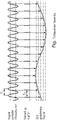
- In 1 shows schematically how a high-frequency measurement signal is transformed into the low-frequency range by sequential sampling.
- the time-expanded signal in the low-frequency range is an image of the high-frequency original measurement signal.
- Level measurement in liquid media is particularly critical.
- the surface is usually in motion.
- a very fast measurement value generation in the range of less than or equal to 1ms is necessary.
- known radar systems use very high transmission pulse rates in the range of several MHz, so that enough sampling points for the envelope curve to be evaluated can be recorded in a short time and so there is enough time for the necessary averaging of the measured values.
- the sampling takes place by cross-correlation of the transmission pulse and the scanning or sample pulse, the scanning pulse having a slightly longer period than the transmission pulse.
- the cross-correlation product is then integrated into a stretched time signal. Correlation and integration can be easily implemented with analog components.
- the factor by which the time signal is expanded is preferably greater than 80,000.
- the expanded time signals can be digitized and evaluated using simple means.
- a laser-based level gauge which is based on this principle of sub-sampling, is, inter alia, in the European patent application EP0015566 A1 disclosed.
- the permitted laser power and the firing rate are again significantly restricted compared to the expensive and rare wavelengths in the near infrared range such as 1060 or 1500nm.
- Geo scanners often use the very expensive technology in the near infrared range at around 1500nm due to the required fast firing rate with high laser power.
- a laser-based level gauge which is based on a variant of real-time scanning, is, for example, in the international publication WO 2009/121181 A1 described.
- the object of the invention is to propose a method and a device for laser-based fill level measurement that are suitable for use in automation technology.
- the object is achieved with regard to the method for laser-based determination of the fill level of a filling material in a container according to a transit time method in that laser pulses of a predetermined pulse width are generated, that the laser pulses are emitted with a defined transmission repetition frequency in the direction of the surface of the filling material, that the defined transmission repetition frequency of the laser pulses is in a defined dependency on a sampling frequency, that the defined dependency is so pronounced that an integer number of periods of the sampling frequency is greater or smaller by a predetermined time interval than a period duration of the transmission repetition frequency, that this time interval is selected in such a way that it one corresponds to the desired sample resolution and is smaller than the period of the sampling frequency, that the laser pulses are received after reflection on the surface of the filling material, that the laser pulses reflected on the surface of the filling material are sampled with a sampling frequency such that several sampled values are recorded per laser pulse and each as Sub-echo curves are stored, that the stored sub-echo curves are assembled into a total echo curve
- the solution according to the invention is preferably used to determine the filling level of liquid media.
- the speed of the acquisition of measured values is so high that a level measured value is obtained from measurements during a time interval in which the usually dynamically changing liquid surface essentially behaves like a static surface.
- An advantageous embodiment of the method according to the invention provides that the defined dependency between the defined transmission repetition frequency and the sampling frequency is realized by the transmission repetition frequency and the sampling frequency being generated by two different frequency-generating components (e.g. oscillators), that a constant difference frequency between the transmission repetition frequency and the Sampling frequency is set via a control loop, and that the transmission repetition frequency and the sampling frequency are obtained either directly from the frequencies generated by the components, or that the transmission repetition frequency and the sampling frequency are obtained indirectly by multiplying or dividing the two frequencies generated by the components.
- two different frequency-generating components e.g. oscillators
- the predetermined dependency between the defined transmission repetition frequency and the sampling frequency is realized by using a first frequency-generating component to generate a fundamental frequency that is greater than the transmission repetition frequency, so that the fundamental frequency is multiplied by a predetermined division factor to obtain the Transmission repetition frequency is obtained, and that the sampling frequency is generated via a second frequency-generating component.
- This choice of divider factor allows for an inexpensive and simple circuit arrangement, since the digital frequency signals through the use of Eg T-FlipFlops (Toggle FlipFlops) can be halved or doubled for each passing gate.
- the method of the invention can be described as multiple sub-echo curve scanning.
- the method requires several periodic laser pulses to reconstruct an envelope.
- the number is lower by a factor of e.g. 300 compared to the known and previously described evaluation for radar measuring devices.
- the methods differ by about two orders of magnitude. This inevitably results in a higher measuring speed.
- higher laser powers are possible due to the slower laser pulse rate, which makes it possible to meet the requirements in level measurement technology.
- An advantageous embodiment of the method according to the invention provides that the basic frequency and the scanning frequency of the laser pulses are preferably in a frequency range of 100-200 MHz.
- a further development of the method according to the invention provides that the time interval for the provision of the level measurement values is selected in such a way that, on the one hand, the requirements for the measurement accuracy of the laser-based technology for use in level measurement technology in liquid media are met and, on the other hand, the safety requirements for the users of the laser-based technology are met will.
- the filling level measurement values of a measurement cycle are provided at a time interval of less than 1 ms.
- a difference frequency is generated, which is regulated to a constant value.
- the basic frequency and the sampling frequency are preferably used directly for the formation of the difference.
- the method according to the invention provides that, depending on the desired resolution or measurement accuracy, several sub-echo curves are recorded, with the sampled values of the individual sub-echo curves being shifted relative to one another by a defined time interval due to the fundamental frequency, the sampling frequency, the difference frequency and the division factor.
- a measurement cycle is completed after the difference frequency has been beaten through, ie when the difference frequency has run through a period and the fundamental frequency and the sampling frequency are again in phase.
- the measurement begins - a measurement cycle starts.
- Laser pulses are now emitted in the laser cycle with the laser pulse rate of 12 kHz.
- a sampling frequency of 200MHz one sampling value is recorded for every 0.75 meter of distance. For example, e.g. 100 values result in the first sub-envelope.
- Due to the differential frequency of 800Hz the scanning of the second laser pulse is shifted by 5 cm compared to the laser pulse; it is therefore delayed. This sampling gives the second sub-envelope.
- the procedure is continued. After 15 scans and sub-echo curves each shifted by 5 cm, the 75 cm between two scan points are closed.
- the overall echo curve is composed by writing the values of the first sub-echo curve, e.g. to memory locations 0, 15, 30, 45...
- the values of the second sub-envelope or sub-echo curve are then written at positions 1, 16, 31, 46, ..
- the values of the third sub-echo curve are written at positions 2, 17, 32, 47,.. etc.
- the memory is complete and can be read out as a total echo curve.
- the transmitter unit is preferably a pulsed laser diode, a laser driver circuit and an optical lens for focusing the laser light.
- the receiving unit preferably consists of a photodiode and an optical one Converging lens for focusing the laser light reflected from the surface of the medium onto the photodiode.
- the photodiode can be an avalanche photodiode and a transimpedance amplifier.
- the scanning circuit be an analog/digital converter and the evaluation unit be a microprocessor.
- the predetermined pulse width of the laser pulses is between 1 ns and 10 ns. It goes without saying that the invention is not limited to this pulse width range. Rather, the pulse width can be adapted to the respective application. As already mentioned, the requirements for liquid measurements are higher than for solid measurements.
- the division factor is preferably 1/ 2n .
- n can have the values 1, 2, 3, ....
- the divider factor can be chosen arbitrarily. The aforementioned divider factor is very advantageous for digitization.
- 1 shows a schematic representation of the known transformation of a high-frequency signal into the low-frequency range.
- very high sampling frequencies and therefore fast and very expensive components are required, which also have high power consumption. Due to the high costs, the high power consumption and the necessary precision, a method is used in radar measurement technology that uses numerous periodically very rapidly recurring transmission pulses to determine an echo curve or an echo curve.
- the very fast signals are transformed into a usable expanded time signal by means of a sequential sampling or sampling method.
- the expanded time signal can then be digitized and evaluated using slower and significantly cheaper components.
- is shown in 1 the sequential sampling of a sine wave.
- the sampling time T2 is slightly longer than the signal period T1. After sequential scanning, a time-expanded image of the original transmission pulse is available at the output.
- Radar level gauges from Endress+Hauser work according to the process described above.
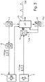
- the signal generation unit 1 generates signals with a fundamental frequency f, which are fed to the pulse shaper 6 and the microprocessor 5.
- the pulse shaper 6 generates laser pulses with a predetermined pulse width Tp from the signals 2 not separately shown contents sent out.
- the AD converter 4 is started via the frequency multiplier 7 .
- the transmission pulse is emitted, the information about the start signal or about the zero reference signal is given to the microprocessor 5 .
- the time period between the receipt of the zero reference signal and the signal reflected by the measurement object is measured.
- the laser pulses reflected on the surface of the filling material are after a period dependent on the distance and therefore on the filling level of the filling material Receiver unit 3 received.
- the received laser pulses are fed to the sampling circuit 4, here a correspondingly designed fast AD converter, which samples the laser pulses in real time.
- the sampling frequency is greater by a factor m than the fundamental frequency f generated by the signal generation unit 1. A large number of individual values are therefore recorded for each laser pulse.
- the evaluation unit 5, here a microprocessor uses the laser pulses scanned in real time to generate the echo curve EK and uses the echo curve EK to determine the filling level of the filling material in the container.
- the signal generation unit 1 generates signals with a fundamental frequency f. These signals with the fundamental frequency f are fed to the pulse shaper 6 and the microprocessor 5 . From the signals, the pulse shaper 6 generates laser pulses with a specified pulse width Tp or a specified transmission repetition frequency ⁇ pulses .
- the predetermined pulse width Tp of the laser pulses is preferably between 1 ns and 10 ns. The measuring accuracy achieved with this allows level measurement on moving surfaces with liquid filling goods.
- the laser pulses are sent by the transmitter unit 2 in the direction of the surface of the in 3 likewise not shown separately.
- the microprocessor 5 receives a start signal for beginning the measurement.
- the laser pulses reflected on the surface of the filling material are received in the receiving unit 3 after a transit time that is dependent on the distance and therefore on the filling level of the filling material.
- the received laser pulses are fed to the sampling circuit 4, here an AD converter.
- the laser pulses are scanned with a scanning frequency f S which differs slightly from the basic frequency f.
- the sampling frequency is generated by the signal generation unit 8, eg an oscillator.
- the difference frequency f diff between the sampling frequency f S and the basic frequency f is regulated to a constant amount. Numerical examples have already been mentioned above.
- a measurement cycle is completed by the microprocessor 5 after the difference frequency f diff has been beaten through, ie when the difference frequency f diff has run through a period T and the fundamental frequency f and the sampling frequency f S are again in phase.
- the sampling values of the individual sub-echo curves SEKx are recorded, with the sampling values of the individual sub-echo curves SEKx being based on the fundamental frequency f , the sampling frequency f s , the Difference frequency f diff and the division factor TF are each shifted to one another by a defined time interval ⁇ t.
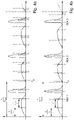
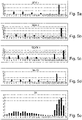
- the evaluation is simplified. The aforesaid is shown graphically in the figures Figures 4a and 4b and in the figures Figures 5a-5e .
- FIGS. 4a and 4b show schematic representations of temporally successive sub-echo curves SEK1, SEK2, SEK3, ...
- the transmission repetition frequency f pulses of the laser pulses has a defined dependency on the sampling frequency f s , which is also referred to as the sampling frequency.
- the defined dependency is such that an integral number of periods of the sampling frequency f S is greater by a predetermined time interval T d than a period of the transmission repetition frequency f Pulse . This case is in Figure 4a too shown.
- Figure 4b shows the case in which an integral number of periods of the sampling frequency f S is smaller by a predetermined time interval T d than a period duration of the transmission repetition frequency f Pulse .
- the time interval T d is selected in each case in such a way that a desired scanning or sample resolution is achieved, with the time interval T d being smaller than the period duration of the scanning frequency f S .
Claims (11)
- Procédé destiné à la détermination par laser du niveau d'un produit dans un réservoir selon une méthode du temps de transit,des impulsions laser d'une largeur d'impulsion (Tp) prédéfinie étant générées, les impulsions laser étant émises avec une fréquence de répétition d'émission (f Pulse ) définie en direction de la surface du produit,la fréquence de répétition d'émission (f Pulse) définie des impulsions laser dépendant d'une fréquence d'échantillonnage (fS ) de telle sorte qu'un nombre entier de périodes de la fréquence d'échantillonnage (fS ) est supérieur ou inférieur d'un intervalle de temps prédéfini (Td ) à une durée de période de la fréquence de répétition d'émission (f Pulse ),cet intervalle de temps (Td ) étant choisi de manière à correspondre à une résolution d'échantillonnage souhaitée et étant inférieur à la durée de période de la fréquence d'échantillonnage (fS ),les impulsions laser étant reçues après réflexion à la surface du produit,les impulsions laser réfléchies à la surface du produit étant échantillonnées à une fréquence d'échantillonnage (fS ) de telle sorte que plusieurs valeurs d'échantillonnage sont détectées par impulsion laser et sont respectivement enregistrées en tant que courbe de sous-écho (SEK),les courbes de sous-écho (SEK) enregistrées étant assemblées après un cycle de mesure pour former une courbe d'écho globale (EK),la dépendance prédéfinie entre la fréquence de répétition d'émission (f Pulse) définie et la fréquence de balayage (fS ) étant réalisée en générant, par l'intermédiaire d'un premier composant générateur de fréquence (1), une fréquence de base (f) qui est supérieure à la fréquence de répétition d'émission (f Pulse ),la fréquence de répétition d'émission (f Pulse) étant obtenue à partir de la fréquence de base (f) par multiplication par un facteur de division (TF) prédéfini, etla fréquence d'échantillonnage (fS ) étant générée par l'intermédiaire d'un deuxième composant générateur de fréquence (8),une fréquence différentielle (fdiff ) étant générée à l'aide de la fréquence de base (f) et de la fréquence d'échantillonnage (fS ), laquelle est régulée à une valeur constante,plusieurs courbes de sous-écho (SEKx) étant enregistrées en fonction de la résolution ou de la précision de mesure souhaitée, les valeurs d'échantillonnage des différentes courbes de sous-écho (SEKx) étant respectivement décalées les unes par rapport aux autres d'un intervalle de temps défini (Δt) en raison de la fréquence de base (f), de la fréquence d'échantillonnage (fS ), de la fréquence différentielle (fdiff ) et du facteur de division (TF),un cycle de mesure étant terminé après le passage de la fréquence différentielle (fdiff ) lorsque la fréquence différentielle (fdiff ) a traversé une période (T) et que la fréquence de base (f) et la fréquence d'échantillonnage (fS ) sont à nouveau en phase,etle niveau étant déterminé à l'aide de la courbe d'écho globale (EK).
- Procédé selon la revendication 1,pour lequel une fréquence différentielle constante entre la fréquence de répétition d'émission (f Pulse) et la fréquence d'échantillonnage (fS ) est réglée par l'intermédiaire d'un circuit de régulation (5, 8), et la fréquence de répétition d'émission (f Pulse) et la fréquence d'échantillonnage (fS ) sont obtenues directement à partir des fréquences (f Pulse , fS ) générées par les composants (1, 8), oupour lequel la fréquence de répétition d'émission (f Pulse) et la fréquence d'échantillonnage (fS ) sont obtenues indirectement par multiplication ou division des deux fréquences (f Pulse, fs ) générées par les composants (1, 8).
- Procédé selon la revendication 1 ou 2,
pour lequel le facteur de division est 1/2n (avec n = 1, 2, 3, ...). - Procédé selon la revendication 1, 2 ou 3,
pour lequel la fréquence de base (f) et la fréquence d'échantillonnage (fS ) des impulsions laser se situent dans une gamme de fréquences de 100-200 MHz. - Procédé selon la revendication 1, 2, 3 ou 4,
pour lequel l'intervalle de temps pour la mise à disposition des valeurs mesurées de niveau est choisi de manière à satisfaire, d'une part, aux exigences de précision de mesure de la technologie à base de laser pour l'application dans la technique de mesure de niveau et, d'autre part, aux exigences de sécurité pour les utilisateurs de la technologie à base de laser. - Procédé selon la revendication 5,
pour lequel les valeurs mesurées de niveau d'un cycle de mesure sont mises à disposition selon un intervalle de temps inférieur à 1 ms. - Procédé selon l'une des revendications précédentes,
pour lequel, pour la formation de la différence (fdiff = f -fs ), on utilise directement la fréquence de base (f) et la fréquence d'échantillonnage (fs ). - Dispositif à base de laser, conçu pour déterminer le niveau d'un produit dans un réservoir selon une méthode du temps de transit selon au moins l'une des revendications précédentes,avec une unité de génération de signaux (1), laquelle est conçue pour générer des impulsions laser avec une largeur d'impulsion (Tp) prédéfinie,avec une unité d'émission (2), laquelle est conçue pour émettre les impulsions laser avec une fréquence de répétition d'émission (f Pulse) définie en direction de la surface du produit,la fréquence de répétition d'émission définie (f Pulse) des impulsions laser étant obtenue par multiplication d'une fréquence de base (f) prédéfinie par un facteur de division (TF), oula fréquence de base étant obtenue par multiplication d'une fréquence de répétition d'émission (f Pulse ) définie par un facteur prédéfini,avec une unité de réception (3), laquelle est conçue pour recevoir les impulsions laser après réflexion sur la surface du produit,avec un premier composant générateur de fréquence (1), lequel est conçu pour générer la fréquence de base (f) qui est supérieure à la fréquence de répétition d'émission (f Pulse ),avec un deuxième composant générateur de fréquence (8), lequel est conçu pour générer une fréquence d'échantillonnage (fS ) légèrement différente de la fréquence de base (f),une fréquence différentielle (fdiff ) entre la fréquence de base et la fréquence d'échantillonnage (fS ) étant régulée à une valeur constante,la fréquence de répétition d'émission (f Pulse) définie des impulsions laser étant en relation de dépendance avec la fréquence d'échantillonnage (fS ) de telle sorte qu'un nombre entier de périodes de la fréquence d'échantillonnage (fS ) soit supérieur ou inférieur d'un intervalle de temps prédéterminé (Td ) à une durée de période de la fréquence de répétition d'émission (f Pulse), etcet intervalle de temps (Td ) étant choisi de telle sorte qu'il corresponde à une résolution d'échantillonnage souhaitée et qu'il soit inférieur à la durée de période de la fréquence d'échantillonnage (fS ),avec un circuit d'échantillonnage (4), lequel est conçu pour échantillonner les impulsions laser réfléchies à la surface du produit avec la fréquence d'échantillonnage (fS ), de telle sorte que plusieurs valeurs d'échantillonnage sont détectées par impulsion laser et sont respectivement enregistrées comme courbe de sous-écho (SEK),les valeurs d'échantillonnage des différentes courbes de sous-écho (SEKx) étant respectivement décalées les unes par rapport aux autres d'un intervalle de temps (Δt) défini en raison de la fréquence de base (f), de la fréquence de balayage (fS ), de la fréquence différentielle (fdiff ) et du facteur de division (TF),un cycle de mesure étant achevé après le passage de la fréquence différentielle (fdiff ) lorsque la fréquence différentielle (fdiff ) a traversé une période (T) et que la fréquence de base (f) et la fréquence d'échantillonnage (fS ) sont à nouveau en phase,etavec une unité d'exploitation (5) qui est conçue pour assembler les courbes de sous-écho (SEK) enregistrées après un cycle de mesure en une courbe d'écho globale (EK) et pour déterminer le niveau de produit dans le réservoir à l'aide de la courbe d'écho globale (EK).
- Dispositif selon la revendication 8,
pour lequel le circuit d'échantillonnage (4) est un convertisseur analogique/numérique et l'unité d'exploitation (5) est un microprocesseur. - Dispositif selon la revendication 8 ou 9,
pour lequel la largeur d'impulsion (Tp) prédéfinie des impulsions laser est de préférence comprise entre 1 ns et 10 ns. - Dispositif selon l'une ou plusieurs des revendications 8 à 10,
pour lequel le facteur de division (TF) est 1/2n avec n = 1, 2, 3, ...
Applications Claiming Priority (2)
| Application Number | Priority Date | Filing Date | Title |
|---|---|---|---|
| DE102012106149.1A DE102012106149A1 (de) | 2012-07-09 | 2012-07-09 | Verfahren und Vorrichtung zur laserbasierten Bestimmung des Füllstands eines Füllguts in einem Behälter |
| PCT/EP2013/061805 WO2014009068A1 (fr) | 2012-07-09 | 2013-06-07 | Procédé et dispositif pour la détermination basée sur laser du niveau de remplissage d'une matière de remplissage dans un récipient |
Publications (2)
| Publication Number | Publication Date |
|---|---|
| EP2870438A1 EP2870438A1 (fr) | 2015-05-13 |
| EP2870438B1 true EP2870438B1 (fr) | 2022-05-11 |
Family
ID=48628639
Family Applications (1)
| Application Number | Title | Priority Date | Filing Date |
|---|---|---|---|
| EP13729299.1A Active EP2870438B1 (fr) | 2012-07-09 | 2013-06-07 | Procédé et dispositif pour la détermination basée sur laser du niveau de remplissage d'une matière de remplissage dans un récipient |
Country Status (4)
| Country | Link |
|---|---|
| EP (1) | EP2870438B1 (fr) |
| CN (1) | CN104471358A (fr) |
| DE (1) | DE102012106149A1 (fr) |
| WO (1) | WO2014009068A1 (fr) |
Families Citing this family (7)
| Publication number | Priority date | Publication date | Assignee | Title |
|---|---|---|---|---|
| DE102012108462A1 (de) | 2012-09-11 | 2014-03-13 | Endress + Hauser Gmbh + Co. Kg | Verfahren, Vorrichtung und System zur Laserbasierten Bestimmung des Füllstands eines Füllguts in einem Behälter |
| DE102012108460A1 (de) | 2012-09-11 | 2014-03-13 | Endress + Hauser Gmbh + Co. Kg | Verfahren zur Laserbasierten Bestimmung von zumindest einer Mediums- und/oder Prozesseigenschaft |
| DE102013114737A1 (de) | 2013-12-20 | 2015-06-25 | Endress + Hauser Gmbh + Co. Kg | Laser-basierte Füllstandsmessvorrichtung |
| CN107462302B (zh) * | 2017-08-02 | 2019-06-21 | 浙江中产科技有限公司 | 一种激光料位数据处理的方法 |
| CN107907184B (zh) * | 2017-12-01 | 2019-08-02 | 浙江中产科技有限公司 | 一种采用两种波长激光配合测量料位距离的方法 |
| US11079268B2 (en) | 2017-12-21 | 2021-08-03 | Rosemount Inc. | Precision ADC sampling clock for high accuracy wireless guided wave radar |
| EP3690480A1 (fr) * | 2019-01-30 | 2020-08-05 | Silicon Austria Labs GmbH | Procédé de mesure de durée de vol d'impulsions |
Family Cites Families (11)
| Publication number | Priority date | Publication date | Assignee | Title |
|---|---|---|---|---|
| DE2908854C2 (de) * | 1979-03-07 | 1986-04-17 | Endress U. Hauser Gmbh U. Co, 7867 Maulburg | Entfernungsmeßgerät nach dem Impulslaufzeitverfahren |
| DE68925998T2 (de) * | 1988-06-29 | 1996-09-12 | Topcon Corp | Hochauflösendes Zeitdifferenzmessgerät |
| EP0955527B1 (fr) * | 1998-05-05 | 2007-06-27 | Endress + Hauser GmbH + Co. KG | Détecteur de niveau à micro-ondes |
| DE19961855B4 (de) * | 1999-12-22 | 2007-11-29 | Endress + Hauser Gmbh + Co. Kg | Verfahren und Vorrichtung zur Bestimmung des Füllstands eines Füllguts in einem Behälter |
| DE10106681A1 (de) * | 2001-02-14 | 2003-01-02 | Endress & Hauser Gmbh & Co Kg | Vorrichtung zur Bestimmung des Füllstands eines Füllguts in einem Behälter |
| WO2005008271A2 (fr) * | 2002-11-26 | 2005-01-27 | Munro James F | Procedes et appareil de mesure de haute precision de la distance et de la vitesse |
| US7412337B2 (en) * | 2005-10-13 | 2008-08-12 | Endress + Hauser Gmbh + Co. Kg | Method for determining fill level on the basis of travel time of a high-frequency measuring signal |
| EP1882959A1 (fr) * | 2006-07-17 | 2008-01-30 | Leica Geosystems AG | Procédé de mesure de distance optique et télémètre optique correspondant |
| US7640122B2 (en) * | 2007-11-07 | 2009-12-29 | Institut National D'optique | Digital signal processing in optical systems used for ranging applications |
| JP5671345B2 (ja) * | 2007-12-21 | 2015-02-18 | レッダーテック インコーポレイテッド | 検出及び測距方法 |
| EP2265909B8 (fr) * | 2008-04-04 | 2017-07-26 | Leddartech Inc. | Dispositif et procédé de mesure du niveau optique |
-
2012
- 2012-07-09 DE DE102012106149.1A patent/DE102012106149A1/de not_active Withdrawn
-
2013
- 2013-06-07 EP EP13729299.1A patent/EP2870438B1/fr active Active
- 2013-06-07 WO PCT/EP2013/061805 patent/WO2014009068A1/fr active Application Filing
- 2013-06-07 CN CN201380036697.1A patent/CN104471358A/zh active Pending
Also Published As
| Publication number | Publication date |
|---|---|
| DE102012106149A1 (de) | 2014-01-09 |
| WO2014009068A1 (fr) | 2014-01-16 |
| EP2870438A1 (fr) | 2015-05-13 |
| CN104471358A (zh) | 2015-03-25 |
Similar Documents
| Publication | Publication Date | Title |
|---|---|---|
| EP2870438B1 (fr) | Procédé et dispositif pour la détermination basée sur laser du niveau de remplissage d'une matière de remplissage dans un récipient | |
| EP0834086B1 (fr) | Procede de mesure de distances en ondes entretenues de frequence modulee | |
| EP2626722B1 (fr) | Capteur optoélectronique et procédé destiné à la détection et la détermination de l'éloignement d'objets | |
| EP0955527A1 (fr) | Détecteur de niveau à micro-ondes | |
| DE2008256C3 (de) | Laser-Entfernungsmeßsystem mit Impulskompression der Echos frequenzmodulierter Laserimpulse | |
| DE3038961A1 (de) | Einrichtung zur bestimmung von daten eines signalausbreitungsweges, insbesondere nach dem rueckstrahlprinzip arbeitendes messsystem | |
| EP0882956A2 (fr) | Procédé de mesure du niveau d'un matériau dans un réservoir suivant le principle radar | |
| DE4406865C2 (de) | Abstandsmeßvorrichtung | |
| DE102012112985B3 (de) | Entfernungsmessender optoelektronischer Sensor und Verfahren zur Erfassung und Abstandsbestimmung von Objekten | |
| EP2315053A2 (fr) | Dispositifs et procédé de mesure des moments de réception d'impulsions | |
| WO2018172369A1 (fr) | Dispositif de mesure lidar | |
| EP0427969B1 (fr) | Dispositif de mesure du temps de vol d'une impulsion | |
| DE2723355C2 (de) | Verfahren und Anordnung zum Auswerten von Radarimpulsfolgen | |
| DE2133497C3 (de) | Verfahren und Anordnung zur Korre lations Entfernungsmessung mittels einer pseudostochastischen Impulsfolge | |
| DE911663C (de) | Verfahren zur Kontrolle, insbesondere zur Entfernungsbestimmung von Objekten nach dem Rueckstrahlprinzip durch impulsweises Aussenden und Wiederempfangen von hochfrequenten Schwingungen | |
| EP0303156B1 (fr) | Procédé pour anémomètrie laser-doppler | |
| EP2766742A1 (fr) | Procédé et dispositif de mesure optique de distances sur de grandes étendues | |
| DE3120274C2 (de) | Entfernungsmeßgerät | |
| DE102008045366B4 (de) | Vorrichtung und Verfahren zur Geschwindigkeitsmessung | |
| DE10149423B4 (de) | Verfahren und Vorrichtung zur Messung von Entfernungen in optisch trüben Medien | |
| DE3324341C2 (de) | Einrichtung zur genauen Bestimmung kurzer Laufzeiten von elektronisch erzeugten Impulsen | |
| DE10025968A1 (de) | Verfahren und Schaltungsanordnung zur Entfernungsmessung nach dem Echolaufzeitprinzip | |
| DE1773287B1 (de) | Vorrichtung zur radioelektrischen entfernungsmessung | |
| EP2881706B1 (fr) | Procédé de mesure d'eaux | |
| DE102012108460A1 (de) | Verfahren zur Laserbasierten Bestimmung von zumindest einer Mediums- und/oder Prozesseigenschaft |
Legal Events
| Date | Code | Title | Description |
|---|---|---|---|
| PUAI | Public reference made under article 153(3) epc to a published international application that has entered the european phase |
Free format text: ORIGINAL CODE: 0009012 |
|
| 17P | Request for examination filed |
Effective date: 20141210 |
|
| AK | Designated contracting states |
Kind code of ref document: A1 Designated state(s): AL AT BE BG CH CY CZ DE DK EE ES FI FR GB GR HR HU IE IS IT LI LT LU LV MC MK MT NL NO PL PT RO RS SE SI SK SM TR |
|
| AX | Request for extension of the european patent |
Extension state: BA ME |
|
| RIN1 | Information on inventor provided before grant (corrected) |
Inventor name: DAMM, HARTMUT Inventor name: SEILER, CHRISTIAN Inventor name: JIANG, MINGZHENG Inventor name: SCHLEIFERBOECK, JAN |
|
| DAX | Request for extension of the european patent (deleted) | ||
| RAP1 | Party data changed (applicant data changed or rights of an application transferred) |
Owner name: ENDRESS+HAUSER SE+CO. KG |
|
| STAA | Information on the status of an ep patent application or granted ep patent |
Free format text: STATUS: EXAMINATION IS IN PROGRESS |
|
| 17Q | First examination report despatched |
Effective date: 20181015 |
|
| STAA | Information on the status of an ep patent application or granted ep patent |
Free format text: STATUS: EXAMINATION IS IN PROGRESS |
|
| GRAP | Despatch of communication of intention to grant a patent |
Free format text: ORIGINAL CODE: EPIDOSNIGR1 |
|
| STAA | Information on the status of an ep patent application or granted ep patent |
Free format text: STATUS: GRANT OF PATENT IS INTENDED |
|
| INTG | Intention to grant announced |
Effective date: 20220110 |
|
| GRAS | Grant fee paid |
Free format text: ORIGINAL CODE: EPIDOSNIGR3 |
|
| GRAA | (expected) grant |
Free format text: ORIGINAL CODE: 0009210 |
|
| STAA | Information on the status of an ep patent application or granted ep patent |
Free format text: STATUS: THE PATENT HAS BEEN GRANTED |
|
| AK | Designated contracting states |
Kind code of ref document: B1 Designated state(s): AL AT BE BG CH CY CZ DE DK EE ES FI FR GB GR HR HU IE IS IT LI LT LU LV MC MK MT NL NO PL PT RO RS SE SI SK SM TR |
|
| REG | Reference to a national code |
Ref country code: GB Ref legal event code: FG4D Free format text: NOT ENGLISH |
|
| REG | Reference to a national code |
Ref country code: CH Ref legal event code: EP |
|
| REG | Reference to a national code |
Ref country code: AT Ref legal event code: REF Ref document number: 1491789 Country of ref document: AT Kind code of ref document: T Effective date: 20220515 |
|
| REG | Reference to a national code |
Ref country code: DE Ref legal event code: R096 Ref document number: 502013016142 Country of ref document: DE |
|
| REG | Reference to a national code |
Ref country code: IE Ref legal event code: FG4D Free format text: LANGUAGE OF EP DOCUMENT: GERMAN |
|
| REG | Reference to a national code |
Ref country code: LT Ref legal event code: MG9D |
|
| REG | Reference to a national code |
Ref country code: NL Ref legal event code: MP Effective date: 20220511 |
|
| PG25 | Lapsed in a contracting state [announced via postgrant information from national office to epo] |
Ref country code: SE Free format text: LAPSE BECAUSE OF FAILURE TO SUBMIT A TRANSLATION OF THE DESCRIPTION OR TO PAY THE FEE WITHIN THE PRESCRIBED TIME-LIMIT Effective date: 20220511 Ref country code: PT Free format text: LAPSE BECAUSE OF FAILURE TO SUBMIT A TRANSLATION OF THE DESCRIPTION OR TO PAY THE FEE WITHIN THE PRESCRIBED TIME-LIMIT Effective date: 20220912 Ref country code: NO Free format text: LAPSE BECAUSE OF FAILURE TO SUBMIT A TRANSLATION OF THE DESCRIPTION OR TO PAY THE FEE WITHIN THE PRESCRIBED TIME-LIMIT Effective date: 20220811 Ref country code: NL Free format text: LAPSE BECAUSE OF FAILURE TO SUBMIT A TRANSLATION OF THE DESCRIPTION OR TO PAY THE FEE WITHIN THE PRESCRIBED TIME-LIMIT Effective date: 20220511 Ref country code: LT Free format text: LAPSE BECAUSE OF FAILURE TO SUBMIT A TRANSLATION OF THE DESCRIPTION OR TO PAY THE FEE WITHIN THE PRESCRIBED TIME-LIMIT Effective date: 20220511 Ref country code: HR Free format text: LAPSE BECAUSE OF FAILURE TO SUBMIT A TRANSLATION OF THE DESCRIPTION OR TO PAY THE FEE WITHIN THE PRESCRIBED TIME-LIMIT Effective date: 20220511 Ref country code: GR Free format text: LAPSE BECAUSE OF FAILURE TO SUBMIT A TRANSLATION OF THE DESCRIPTION OR TO PAY THE FEE WITHIN THE PRESCRIBED TIME-LIMIT Effective date: 20220812 Ref country code: FI Free format text: LAPSE BECAUSE OF FAILURE TO SUBMIT A TRANSLATION OF THE DESCRIPTION OR TO PAY THE FEE WITHIN THE PRESCRIBED TIME-LIMIT Effective date: 20220511 Ref country code: ES Free format text: LAPSE BECAUSE OF FAILURE TO SUBMIT A TRANSLATION OF THE DESCRIPTION OR TO PAY THE FEE WITHIN THE PRESCRIBED TIME-LIMIT Effective date: 20220511 Ref country code: BG Free format text: LAPSE BECAUSE OF FAILURE TO SUBMIT A TRANSLATION OF THE DESCRIPTION OR TO PAY THE FEE WITHIN THE PRESCRIBED TIME-LIMIT Effective date: 20220811 |
|
| PG25 | Lapsed in a contracting state [announced via postgrant information from national office to epo] |
Ref country code: RS Free format text: LAPSE BECAUSE OF FAILURE TO SUBMIT A TRANSLATION OF THE DESCRIPTION OR TO PAY THE FEE WITHIN THE PRESCRIBED TIME-LIMIT Effective date: 20220511 Ref country code: PL Free format text: LAPSE BECAUSE OF FAILURE TO SUBMIT A TRANSLATION OF THE DESCRIPTION OR TO PAY THE FEE WITHIN THE PRESCRIBED TIME-LIMIT Effective date: 20220511 Ref country code: LV Free format text: LAPSE BECAUSE OF FAILURE TO SUBMIT A TRANSLATION OF THE DESCRIPTION OR TO PAY THE FEE WITHIN THE PRESCRIBED TIME-LIMIT Effective date: 20220511 Ref country code: IS Free format text: LAPSE BECAUSE OF FAILURE TO SUBMIT A TRANSLATION OF THE DESCRIPTION OR TO PAY THE FEE WITHIN THE PRESCRIBED TIME-LIMIT Effective date: 20220911 |
|
| PG25 | Lapsed in a contracting state [announced via postgrant information from national office to epo] |
Ref country code: SM Free format text: LAPSE BECAUSE OF FAILURE TO SUBMIT A TRANSLATION OF THE DESCRIPTION OR TO PAY THE FEE WITHIN THE PRESCRIBED TIME-LIMIT Effective date: 20220511 Ref country code: SK Free format text: LAPSE BECAUSE OF FAILURE TO SUBMIT A TRANSLATION OF THE DESCRIPTION OR TO PAY THE FEE WITHIN THE PRESCRIBED TIME-LIMIT Effective date: 20220511 Ref country code: RO Free format text: LAPSE BECAUSE OF FAILURE TO SUBMIT A TRANSLATION OF THE DESCRIPTION OR TO PAY THE FEE WITHIN THE PRESCRIBED TIME-LIMIT Effective date: 20220511 Ref country code: EE Free format text: LAPSE BECAUSE OF FAILURE TO SUBMIT A TRANSLATION OF THE DESCRIPTION OR TO PAY THE FEE WITHIN THE PRESCRIBED TIME-LIMIT Effective date: 20220511 Ref country code: DK Free format text: LAPSE BECAUSE OF FAILURE TO SUBMIT A TRANSLATION OF THE DESCRIPTION OR TO PAY THE FEE WITHIN THE PRESCRIBED TIME-LIMIT Effective date: 20220511 Ref country code: CZ Free format text: LAPSE BECAUSE OF FAILURE TO SUBMIT A TRANSLATION OF THE DESCRIPTION OR TO PAY THE FEE WITHIN THE PRESCRIBED TIME-LIMIT Effective date: 20220511 |
|
| REG | Reference to a national code |
Ref country code: CH Ref legal event code: PL |
|
| REG | Reference to a national code |
Ref country code: DE Ref legal event code: R097 Ref document number: 502013016142 Country of ref document: DE |
|
| REG | Reference to a national code |
Ref country code: BE Ref legal event code: MM Effective date: 20220630 |
|
| PG25 | Lapsed in a contracting state [announced via postgrant information from national office to epo] |
Ref country code: MC Free format text: LAPSE BECAUSE OF FAILURE TO SUBMIT A TRANSLATION OF THE DESCRIPTION OR TO PAY THE FEE WITHIN THE PRESCRIBED TIME-LIMIT Effective date: 20220511 |
|
| PLBE | No opposition filed within time limit |
Free format text: ORIGINAL CODE: 0009261 |
|
| STAA | Information on the status of an ep patent application or granted ep patent |
Free format text: STATUS: NO OPPOSITION FILED WITHIN TIME LIMIT |
|
| PG25 | Lapsed in a contracting state [announced via postgrant information from national office to epo] |
Ref country code: AL Free format text: LAPSE BECAUSE OF FAILURE TO SUBMIT A TRANSLATION OF THE DESCRIPTION OR TO PAY THE FEE WITHIN THE PRESCRIBED TIME-LIMIT Effective date: 20220511 |
|
| 26N | No opposition filed |
Effective date: 20230214 |
|
| GBPC | Gb: european patent ceased through non-payment of renewal fee |
Effective date: 20220811 |
|
| PG25 | Lapsed in a contracting state [announced via postgrant information from national office to epo] |
Ref country code: LU Free format text: LAPSE BECAUSE OF NON-PAYMENT OF DUE FEES Effective date: 20220607 Ref country code: LI Free format text: LAPSE BECAUSE OF NON-PAYMENT OF DUE FEES Effective date: 20220630 Ref country code: IE Free format text: LAPSE BECAUSE OF NON-PAYMENT OF DUE FEES Effective date: 20220607 Ref country code: FR Free format text: LAPSE BECAUSE OF NON-PAYMENT OF DUE FEES Effective date: 20220711 Ref country code: CH Free format text: LAPSE BECAUSE OF NON-PAYMENT OF DUE FEES Effective date: 20220630 |
|
| PG25 | Lapsed in a contracting state [announced via postgrant information from national office to epo] |
Ref country code: SI Free format text: LAPSE BECAUSE OF FAILURE TO SUBMIT A TRANSLATION OF THE DESCRIPTION OR TO PAY THE FEE WITHIN THE PRESCRIBED TIME-LIMIT Effective date: 20220511 Ref country code: BE Free format text: LAPSE BECAUSE OF NON-PAYMENT OF DUE FEES Effective date: 20220630 |
|
| P01 | Opt-out of the competence of the unified patent court (upc) registered |
Effective date: 20230601 |
|
| PGFP | Annual fee paid to national office [announced via postgrant information from national office to epo] |
Ref country code: DE Payment date: 20230620 Year of fee payment: 11 |
|
| REG | Reference to a national code |
Ref country code: AT Ref legal event code: MM01 Ref document number: 1491789 Country of ref document: AT Kind code of ref document: T Effective date: 20220607 |
|
| PG25 | Lapsed in a contracting state [announced via postgrant information from national office to epo] |
Ref country code: GB Free format text: LAPSE BECAUSE OF NON-PAYMENT OF DUE FEES Effective date: 20220811 Ref country code: AT Free format text: LAPSE BECAUSE OF NON-PAYMENT OF DUE FEES Effective date: 20220607 |
|
| PG25 | Lapsed in a contracting state [announced via postgrant information from national office to epo] |
Ref country code: IT Free format text: LAPSE BECAUSE OF FAILURE TO SUBMIT A TRANSLATION OF THE DESCRIPTION OR TO PAY THE FEE WITHIN THE PRESCRIBED TIME-LIMIT Effective date: 20220511 |
|
| PG25 | Lapsed in a contracting state [announced via postgrant information from national office to epo] |
Ref country code: HU Free format text: LAPSE BECAUSE OF FAILURE TO SUBMIT A TRANSLATION OF THE DESCRIPTION OR TO PAY THE FEE WITHIN THE PRESCRIBED TIME-LIMIT; INVALID AB INITIO Effective date: 20130607 |