EP2870438B1 - Method and apparatus for the laser-based determination of the filling level of a filling material in a container - Google Patents
Method and apparatus for the laser-based determination of the filling level of a filling material in a container Download PDFInfo
- Publication number
- EP2870438B1 EP2870438B1 EP13729299.1A EP13729299A EP2870438B1 EP 2870438 B1 EP2870438 B1 EP 2870438B1 EP 13729299 A EP13729299 A EP 13729299A EP 2870438 B1 EP2870438 B1 EP 2870438B1
- Authority
- EP
- European Patent Office
- Prior art keywords
- frequency
- pulse
- scan
- laser
- laser pulses
- Prior art date
- Legal status (The legal status is an assumption and is not a legal conclusion. Google has not performed a legal analysis and makes no representation as to the accuracy of the status listed.)
- Active
Links
- 238000000034 method Methods 0.000 title claims description 45
- 239000000463 material Substances 0.000 title description 16
- 230000005540 biological transmission Effects 0.000 claims description 36
- 238000005516 engineering process Methods 0.000 claims description 15
- 238000011156 evaluation Methods 0.000 claims description 14
- 230000007274 generation of a signal involved in cell-cell signaling Effects 0.000 claims description 6
- 230000001105 regulatory effect Effects 0.000 claims description 6
- 238000005070 sampling Methods 0.000 description 64
- 238000005259 measurement Methods 0.000 description 59
- 238000010304 firing Methods 0.000 description 8
- 239000007788 liquid Substances 0.000 description 8
- 238000010586 diagram Methods 0.000 description 4
- 230000001419 dependent effect Effects 0.000 description 3
- 230000000737 periodic effect Effects 0.000 description 3
- 230000009466 transformation Effects 0.000 description 3
- 102100023274 Dual specificity mitogen-activated protein kinase kinase 4 Human genes 0.000 description 2
- 101710146518 Dual specificity mitogen-activated protein kinase kinase 4 Proteins 0.000 description 2
- 101100172512 Mus musculus Epha2 gene Proteins 0.000 description 2
- 101100445387 Mus musculus Ephb2 gene Proteins 0.000 description 2
- 238000001514 detection method Methods 0.000 description 2
- 239000000428 dust Substances 0.000 description 2
- 230000003287 optical effect Effects 0.000 description 2
- 238000012545 processing Methods 0.000 description 2
- 230000001960 triggered effect Effects 0.000 description 2
- 238000012935 Averaging Methods 0.000 description 1
- 230000003044 adaptive effect Effects 0.000 description 1
- 230000015572 biosynthetic process Effects 0.000 description 1
- 238000006243 chemical reaction Methods 0.000 description 1
- 230000002860 competitive effect Effects 0.000 description 1
- 230000003111 delayed effect Effects 0.000 description 1
- 238000011161 development Methods 0.000 description 1
- 238000005265 energy consumption Methods 0.000 description 1
- 230000007613 environmental effect Effects 0.000 description 1
- 239000002360 explosive Substances 0.000 description 1
- 230000010354 integration Effects 0.000 description 1
- 230000002452 interceptive effect Effects 0.000 description 1
- 239000007787 solid Substances 0.000 description 1
- 210000002023 somite Anatomy 0.000 description 1
- 230000003068 static effect Effects 0.000 description 1
- 238000011426 transformation method Methods 0.000 description 1
- XLYOFNOQVPJJNP-UHFFFAOYSA-N water Substances O XLYOFNOQVPJJNP-UHFFFAOYSA-N 0.000 description 1
Images

Classifications
-
- G—PHYSICS
- G01—MEASURING; TESTING
- G01S—RADIO DIRECTION-FINDING; RADIO NAVIGATION; DETERMINING DISTANCE OR VELOCITY BY USE OF RADIO WAVES; LOCATING OR PRESENCE-DETECTING BY USE OF THE REFLECTION OR RERADIATION OF RADIO WAVES; ANALOGOUS ARRANGEMENTS USING OTHER WAVES
- G01S17/00—Systems using the reflection or reradiation of electromagnetic waves other than radio waves, e.g. lidar systems
- G01S17/02—Systems using the reflection of electromagnetic waves other than radio waves
- G01S17/06—Systems determining position data of a target
- G01S17/08—Systems determining position data of a target for measuring distance only
- G01S17/10—Systems determining position data of a target for measuring distance only using transmission of interrupted, pulse-modulated waves
-
- G—PHYSICS
- G01—MEASURING; TESTING
- G01F—MEASURING VOLUME, VOLUME FLOW, MASS FLOW OR LIQUID LEVEL; METERING BY VOLUME
- G01F23/00—Indicating or measuring liquid level or level of fluent solid material, e.g. indicating in terms of volume or indicating by means of an alarm
- G01F23/22—Indicating or measuring liquid level or level of fluent solid material, e.g. indicating in terms of volume or indicating by means of an alarm by measuring physical variables, other than linear dimensions, pressure or weight, dependent on the level to be measured, e.g. by difference of heat transfer of steam or water
- G01F23/28—Indicating or measuring liquid level or level of fluent solid material, e.g. indicating in terms of volume or indicating by means of an alarm by measuring physical variables, other than linear dimensions, pressure or weight, dependent on the level to be measured, e.g. by difference of heat transfer of steam or water by measuring the variations of parameters of electromagnetic or acoustic waves applied directly to the liquid or fluent solid material
- G01F23/284—Electromagnetic waves
- G01F23/292—Light, e.g. infrared or ultraviolet
- G01F23/2921—Light, e.g. infrared or ultraviolet for discrete levels
- G01F23/2928—Light, e.g. infrared or ultraviolet for discrete levels using light reflected on the material surface
-
- G—PHYSICS
- G01—MEASURING; TESTING
- G01S—RADIO DIRECTION-FINDING; RADIO NAVIGATION; DETERMINING DISTANCE OR VELOCITY BY USE OF RADIO WAVES; LOCATING OR PRESENCE-DETECTING BY USE OF THE REFLECTION OR RERADIATION OF RADIO WAVES; ANALOGOUS ARRANGEMENTS USING OTHER WAVES
- G01S17/00—Systems using the reflection or reradiation of electromagnetic waves other than radio waves, e.g. lidar systems
- G01S17/88—Lidar systems specially adapted for specific applications
-
- G—PHYSICS
- G01—MEASURING; TESTING
- G01S—RADIO DIRECTION-FINDING; RADIO NAVIGATION; DETERMINING DISTANCE OR VELOCITY BY USE OF RADIO WAVES; LOCATING OR PRESENCE-DETECTING BY USE OF THE REFLECTION OR RERADIATION OF RADIO WAVES; ANALOGOUS ARRANGEMENTS USING OTHER WAVES
- G01S7/00—Details of systems according to groups G01S13/00, G01S15/00, G01S17/00
- G01S7/48—Details of systems according to groups G01S13/00, G01S15/00, G01S17/00 of systems according to group G01S17/00
- G01S7/483—Details of pulse systems
- G01S7/486—Receivers
- G01S7/4861—Circuits for detection, sampling, integration or read-out
Definitions
- the invention relates to a method and a device for laser-based determination of the filling level of a filling material in a container using a transit time method.
- TDC Time to Digital Converter
- the known systems only have limited multi-target capability and are therefore not very robust with regard to existing disturbance variables such as steam, fog and dust.
- they are not able to identify faulty or invalid received signals based on the signal shape. Since detection is not possible, invalid signals cannot be suppressed.
- known radar fill level measuring devices use the principle of scanning the entire signal curve of a radar pulse. These known devices record the signal curve as a so-called envelope curve or echo curve and evaluate this for the purpose of determining the measured value using adapted and adaptive algorithms through digital signal processing. With the known method, interference or invalid signals can be specifically identified as such and masked out, so that ideally they do not influence the measurement. Laser-based fill level measuring devices with envelope curve evaluation do not yet exist due to the problems described below.
- Scanning laser systems are already in use in the field of geodata acquisition, which work according to the principle of envelope curve or generally full waveform scanning and forward the recorded signal forms to computing units for further processing.
- the different signal forms are mainly used here to determine the existing geosubstance.
- the geosubstance is, for example, trees, water, bushes, etc. With these systems, the focus is not on an exact one distance determination.
- the known systems are very expensive and work with sampling frequencies in the GHz range. The known systems are unsuitable for level measurement because of insufficient update rates.
- the problem with scanning systems lies in the measurement accuracy required and the measurement speed required.
- very high sampling frequencies and therefore fast and very expensive electronic components are required, which also have a high power consumption.
- the very fast transmission pulses are transformed into an expanded time signal and thus into the low-frequency range by means of a sequential sampling process.
- the time-expanded time signal can be digitized and evaluated with slower and therefore significantly cheaper components.
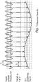
- In 1 shows schematically how a high-frequency measurement signal is transformed into the low-frequency range by sequential sampling.
- the time-expanded signal in the low-frequency range is an image of the high-frequency original measurement signal.
- Level measurement in liquid media is particularly critical.
- the surface is usually in motion.
- a very fast measurement value generation in the range of less than or equal to 1ms is necessary.
- known radar systems use very high transmission pulse rates in the range of several MHz, so that enough sampling points for the envelope curve to be evaluated can be recorded in a short time and so there is enough time for the necessary averaging of the measured values.
- the sampling takes place by cross-correlation of the transmission pulse and the scanning or sample pulse, the scanning pulse having a slightly longer period than the transmission pulse.
- the cross-correlation product is then integrated into a stretched time signal. Correlation and integration can be easily implemented with analog components.
- the factor by which the time signal is expanded is preferably greater than 80,000.
- the expanded time signals can be digitized and evaluated using simple means.
- a laser-based level gauge which is based on this principle of sub-sampling, is, inter alia, in the European patent application EP0015566 A1 disclosed.
- the permitted laser power and the firing rate are again significantly restricted compared to the expensive and rare wavelengths in the near infrared range such as 1060 or 1500nm.
- Geo scanners often use the very expensive technology in the near infrared range at around 1500nm due to the required fast firing rate with high laser power.
- a laser-based level gauge which is based on a variant of real-time scanning, is, for example, in the international publication WO 2009/121181 A1 described.
- the object of the invention is to propose a method and a device for laser-based fill level measurement that are suitable for use in automation technology.
- the object is achieved with regard to the method for laser-based determination of the fill level of a filling material in a container according to a transit time method in that laser pulses of a predetermined pulse width are generated, that the laser pulses are emitted with a defined transmission repetition frequency in the direction of the surface of the filling material, that the defined transmission repetition frequency of the laser pulses is in a defined dependency on a sampling frequency, that the defined dependency is so pronounced that an integer number of periods of the sampling frequency is greater or smaller by a predetermined time interval than a period duration of the transmission repetition frequency, that this time interval is selected in such a way that it one corresponds to the desired sample resolution and is smaller than the period of the sampling frequency, that the laser pulses are received after reflection on the surface of the filling material, that the laser pulses reflected on the surface of the filling material are sampled with a sampling frequency such that several sampled values are recorded per laser pulse and each as Sub-echo curves are stored, that the stored sub-echo curves are assembled into a total echo curve
- the solution according to the invention is preferably used to determine the filling level of liquid media.
- the speed of the acquisition of measured values is so high that a level measured value is obtained from measurements during a time interval in which the usually dynamically changing liquid surface essentially behaves like a static surface.
- An advantageous embodiment of the method according to the invention provides that the defined dependency between the defined transmission repetition frequency and the sampling frequency is realized by the transmission repetition frequency and the sampling frequency being generated by two different frequency-generating components (e.g. oscillators), that a constant difference frequency between the transmission repetition frequency and the Sampling frequency is set via a control loop, and that the transmission repetition frequency and the sampling frequency are obtained either directly from the frequencies generated by the components, or that the transmission repetition frequency and the sampling frequency are obtained indirectly by multiplying or dividing the two frequencies generated by the components.
- two different frequency-generating components e.g. oscillators
- the predetermined dependency between the defined transmission repetition frequency and the sampling frequency is realized by using a first frequency-generating component to generate a fundamental frequency that is greater than the transmission repetition frequency, so that the fundamental frequency is multiplied by a predetermined division factor to obtain the Transmission repetition frequency is obtained, and that the sampling frequency is generated via a second frequency-generating component.
- This choice of divider factor allows for an inexpensive and simple circuit arrangement, since the digital frequency signals through the use of Eg T-FlipFlops (Toggle FlipFlops) can be halved or doubled for each passing gate.
- the method of the invention can be described as multiple sub-echo curve scanning.
- the method requires several periodic laser pulses to reconstruct an envelope.
- the number is lower by a factor of e.g. 300 compared to the known and previously described evaluation for radar measuring devices.
- the methods differ by about two orders of magnitude. This inevitably results in a higher measuring speed.
- higher laser powers are possible due to the slower laser pulse rate, which makes it possible to meet the requirements in level measurement technology.
- An advantageous embodiment of the method according to the invention provides that the basic frequency and the scanning frequency of the laser pulses are preferably in a frequency range of 100-200 MHz.
- a further development of the method according to the invention provides that the time interval for the provision of the level measurement values is selected in such a way that, on the one hand, the requirements for the measurement accuracy of the laser-based technology for use in level measurement technology in liquid media are met and, on the other hand, the safety requirements for the users of the laser-based technology are met will.
- the filling level measurement values of a measurement cycle are provided at a time interval of less than 1 ms.
- a difference frequency is generated, which is regulated to a constant value.
- the basic frequency and the sampling frequency are preferably used directly for the formation of the difference.
- the method according to the invention provides that, depending on the desired resolution or measurement accuracy, several sub-echo curves are recorded, with the sampled values of the individual sub-echo curves being shifted relative to one another by a defined time interval due to the fundamental frequency, the sampling frequency, the difference frequency and the division factor.
- a measurement cycle is completed after the difference frequency has been beaten through, ie when the difference frequency has run through a period and the fundamental frequency and the sampling frequency are again in phase.
- the measurement begins - a measurement cycle starts.
- Laser pulses are now emitted in the laser cycle with the laser pulse rate of 12 kHz.
- a sampling frequency of 200MHz one sampling value is recorded for every 0.75 meter of distance. For example, e.g. 100 values result in the first sub-envelope.
- Due to the differential frequency of 800Hz the scanning of the second laser pulse is shifted by 5 cm compared to the laser pulse; it is therefore delayed. This sampling gives the second sub-envelope.
- the procedure is continued. After 15 scans and sub-echo curves each shifted by 5 cm, the 75 cm between two scan points are closed.
- the overall echo curve is composed by writing the values of the first sub-echo curve, e.g. to memory locations 0, 15, 30, 45...
- the values of the second sub-envelope or sub-echo curve are then written at positions 1, 16, 31, 46, ..
- the values of the third sub-echo curve are written at positions 2, 17, 32, 47,.. etc.
- the memory is complete and can be read out as a total echo curve.
- the transmitter unit is preferably a pulsed laser diode, a laser driver circuit and an optical lens for focusing the laser light.
- the receiving unit preferably consists of a photodiode and an optical one Converging lens for focusing the laser light reflected from the surface of the medium onto the photodiode.
- the photodiode can be an avalanche photodiode and a transimpedance amplifier.
- the scanning circuit be an analog/digital converter and the evaluation unit be a microprocessor.
- the predetermined pulse width of the laser pulses is between 1 ns and 10 ns. It goes without saying that the invention is not limited to this pulse width range. Rather, the pulse width can be adapted to the respective application. As already mentioned, the requirements for liquid measurements are higher than for solid measurements.
- the division factor is preferably 1/ 2n .
- n can have the values 1, 2, 3, ....
- the divider factor can be chosen arbitrarily. The aforementioned divider factor is very advantageous for digitization.
- 1 shows a schematic representation of the known transformation of a high-frequency signal into the low-frequency range.
- very high sampling frequencies and therefore fast and very expensive components are required, which also have high power consumption. Due to the high costs, the high power consumption and the necessary precision, a method is used in radar measurement technology that uses numerous periodically very rapidly recurring transmission pulses to determine an echo curve or an echo curve.
- the very fast signals are transformed into a usable expanded time signal by means of a sequential sampling or sampling method.
- the expanded time signal can then be digitized and evaluated using slower and significantly cheaper components.
- is shown in 1 the sequential sampling of a sine wave.
- the sampling time T2 is slightly longer than the signal period T1. After sequential scanning, a time-expanded image of the original transmission pulse is available at the output.
- Radar level gauges from Endress+Hauser work according to the process described above.
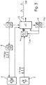
- the signal generation unit 1 generates signals with a fundamental frequency f, which are fed to the pulse shaper 6 and the microprocessor 5.
- the pulse shaper 6 generates laser pulses with a predetermined pulse width Tp from the signals 2 not separately shown contents sent out.
- the AD converter 4 is started via the frequency multiplier 7 .
- the transmission pulse is emitted, the information about the start signal or about the zero reference signal is given to the microprocessor 5 .
- the time period between the receipt of the zero reference signal and the signal reflected by the measurement object is measured.
- the laser pulses reflected on the surface of the filling material are after a period dependent on the distance and therefore on the filling level of the filling material Receiver unit 3 received.
- the received laser pulses are fed to the sampling circuit 4, here a correspondingly designed fast AD converter, which samples the laser pulses in real time.
- the sampling frequency is greater by a factor m than the fundamental frequency f generated by the signal generation unit 1. A large number of individual values are therefore recorded for each laser pulse.
- the evaluation unit 5, here a microprocessor uses the laser pulses scanned in real time to generate the echo curve EK and uses the echo curve EK to determine the filling level of the filling material in the container.
- the signal generation unit 1 generates signals with a fundamental frequency f. These signals with the fundamental frequency f are fed to the pulse shaper 6 and the microprocessor 5 . From the signals, the pulse shaper 6 generates laser pulses with a specified pulse width Tp or a specified transmission repetition frequency ⁇ pulses .
- the predetermined pulse width Tp of the laser pulses is preferably between 1 ns and 10 ns. The measuring accuracy achieved with this allows level measurement on moving surfaces with liquid filling goods.
- the laser pulses are sent by the transmitter unit 2 in the direction of the surface of the in 3 likewise not shown separately.
- the microprocessor 5 receives a start signal for beginning the measurement.
- the laser pulses reflected on the surface of the filling material are received in the receiving unit 3 after a transit time that is dependent on the distance and therefore on the filling level of the filling material.
- the received laser pulses are fed to the sampling circuit 4, here an AD converter.
- the laser pulses are scanned with a scanning frequency f S which differs slightly from the basic frequency f.
- the sampling frequency is generated by the signal generation unit 8, eg an oscillator.
- the difference frequency f diff between the sampling frequency f S and the basic frequency f is regulated to a constant amount. Numerical examples have already been mentioned above.
- a measurement cycle is completed by the microprocessor 5 after the difference frequency f diff has been beaten through, ie when the difference frequency f diff has run through a period T and the fundamental frequency f and the sampling frequency f S are again in phase.
- the sampling values of the individual sub-echo curves SEKx are recorded, with the sampling values of the individual sub-echo curves SEKx being based on the fundamental frequency f , the sampling frequency f s , the Difference frequency f diff and the division factor TF are each shifted to one another by a defined time interval ⁇ t.
- the evaluation is simplified. The aforesaid is shown graphically in the figures Figures 4a and 4b and in the figures Figures 5a-5e .
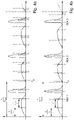
- FIGS. 4a and 4b show schematic representations of temporally successive sub-echo curves SEK1, SEK2, SEK3, ...
- the transmission repetition frequency f pulses of the laser pulses has a defined dependency on the sampling frequency f s , which is also referred to as the sampling frequency.
- the defined dependency is such that an integral number of periods of the sampling frequency f S is greater by a predetermined time interval T d than a period of the transmission repetition frequency f Pulse . This case is in Figure 4a too shown.
- Figure 4b shows the case in which an integral number of periods of the sampling frequency f S is smaller by a predetermined time interval T d than a period duration of the transmission repetition frequency f Pulse .
- the time interval T d is selected in each case in such a way that a desired scanning or sample resolution is achieved, with the time interval T d being smaller than the period duration of the scanning frequency f S .
Description
Die Erfindung betrifft ein Verfahren und eine Vorrichtung zur laserbasierten Bestimmung des Füllstands eines Füllguts in einem Behälter nach einem Laufzeitverfahren.The invention relates to a method and a device for laser-based determination of the filling level of a filling material in a container using a transit time method.
Bekannte Vorrichtungen und Verfahren zur Füllstandmessung mittels Laserpulsen basieren darauf, dass die Laufzeit eines ausgesendeten und an einem Hindernis reflektierten Laserpulses direkt gemessen wird. Hierzu wird die Laufzeit des Laserpulses mittels hochgenauer Bausteine zur Zeitmessung, sog. Time to Digital Converter (TDC), gemessen. Die Arbeitsweise der Bausteine ist vergleichbar mit einer Stoppuhr: Es gibt ein Startsignal und ein Stoppereignis. Das Startsignal wird von einer Sendeelektronik ausgelöst. Das Stoppereignis wird bei Überschreiten einer definierten analogen Schwelle durch das Empfangssignal ausgelöst.Known devices and methods for filling level measurement using laser pulses are based on the fact that the propagation time of a laser pulse that is emitted and reflected by an obstacle is measured directly. For this purpose, the running time of the laser pulse is measured using high-precision components for time measurement, so-called Time to Digital Converter (TDC). The way the blocks work is comparable to a stopwatch: There is a start signal and a stop event. The start signal is triggered by transmission electronics. The stop event is triggered when the received signal exceeds a defined analog threshold.
Grundsätzlich sind die bekannten Systeme nur begrenzt mehrzielfähig und daher wenig robust in Bezug auf vorhandene Störgrößen, wie z.B. Dampf, Nebel und Staub. Darüber hinaus sind sie nicht in der Lage, fehlerhafte oder ungültige Empfangssignale anhand der Signalform zu erkennen. Da die Erkennung nicht möglich ist, können ungültige Signale folglich auch nicht ausgeblendet werden.In principle, the known systems only have limited multi-target capability and are therefore not very robust with regard to existing disturbance variables such as steam, fog and dust. In addition, they are not able to identify faulty or invalid received signals based on the signal shape. Since detection is not possible, invalid signals cannot be suppressed.
Aufgrund dieser Einschränkungen und aufgrund von Störquellen, die ggf. im Messbereich vorhanden sind und entsprechende Störreflexionen verursachen, nutzen bekannte Radar-Füllstandmessgeräte das Prinzip der Abtastung des gesamten Signalverlaufes eines Radarpulses aus. Diese bekannten Geräte nehmen den Signalverlauf als sogenannte Hüllkurve oder Echokurve auf und werten diese zwecks Ermittlung des Messwerts mit angepassten und adaptiven Algorithmen durch digitale Signalverarbeitung aus. Bei der bekannten Methode können Störer oder ungültige Signale gezielt als solche erkannt und ausgeblendet werden, so dass sie die Messung im Idealfall nicht beeinflussen. Laserbasierte Füllstandmessgeräte mit Hüllkurvenauswertung existieren aufgrund der nachfolgend beschriebenen Probleme bislang nicht.Because of these limitations and because of sources of interference that may be present in the measurement area and cause corresponding interference reflections, known radar fill level measuring devices use the principle of scanning the entire signal curve of a radar pulse. These known devices record the signal curve as a so-called envelope curve or echo curve and evaluate this for the purpose of determining the measured value using adapted and adaptive algorithms through digital signal processing. With the known method, interference or invalid signals can be specifically identified as such and masked out, so that ideally they do not influence the measurement. Laser-based fill level measuring devices with envelope curve evaluation do not yet exist due to the problems described below.
Zwar sind im Bereich der Geodaten-Erfassung bereits scannende bzw. abtastende Lasersysteme im Einsatz, die nach dem Prinzip der Hüllkurven- oder allgemein der Full Waveform Abtastung arbeiten und die aufgenommenen Signalformen an Recheneinheiten zwecks Weiter-verarbeitung weiterleiten. Jedoch werden die unterschiedlichen Signalformen hier hauptsächlich dazu verwendet, die vorhandene Geosubstanz zu ermitteln. Bei der Geosubstanz handelt es sich z.B. um Bäume, Wasser, Buschwerk, etc. Bei diesen Systemen liegt der Fokus nicht auf einer exakten Abstandsermittlung. Die bekannten Systeme sind sehr teuer und arbeiten mit Sampling Frequenzen im GHz-Bereich. Für die Füllstandmessung sind die bekannten Systeme wegen nicht ausreichender Update-Raten ungeeignet.Scanning laser systems are already in use in the field of geodata acquisition, which work according to the principle of envelope curve or generally full waveform scanning and forward the recorded signal forms to computing units for further processing. However, the different signal forms are mainly used here to determine the existing geosubstance. The geosubstance is, for example, trees, water, bushes, etc. With these systems, the focus is not on an exact one distance determination. The known systems are very expensive and work with sampling frequencies in the GHz range. The known systems are unsuitable for level measurement because of insufficient update rates.
Die Problematik bei abtastenden Systemen vor allem im Bereich der Füllstandmessung liegt in der hierbei geforderten Messgenauigkeit und in der hierbei geforderten Messgeschwindigkeit. Um die geforderte Messgenauigkeit bei Pulsbreiten von 1- 5 ns zu erreichen, sind sehr hohe Abtastfrequenzen und daher schnelle und sehr teure Elektronikkomponenten erforderlich, die darüber hinaus auch noch einen hohen Stromverbrauch aufweisen. Aufgrund der hohen Kosten, aufgrund des hohen Stromverbrauchs und aufgrund der notwendigen Präzision verwendet man in der RadarMesstechnik ein Verfahren, das zur Ermittlung einer Hüllkurve zahlreiche periodisch sehr schnell wiederkehrende Sendepulse verwendet. Durch ein sequentielles Abtast- bzw. Sampling-Verfahren werden die sehr schnellen Sendepulse in ein gedehntes Zeitsignal und damit in den Niederfrequenzbereich transformiert. Das zeitlich gedehnte Zeitsignal lässt sich mit langsameren und damit deutlich billigeren Komponenten digitalisieren und auswerten. In
Besonders kritisch ist die Füllstandmessung bei flüssigen Medien. Hier ist die Oberfläche üblicherweise in Bewegung. Zur hochgenauen Detektion des Füllstands ist eine sehr schnelle Messwerterzeugung im Bereich kleiner oder gleich 1ms notwendig.Level measurement in liquid media is particularly critical. Here the surface is usually in motion. For high-precision detection of the filling level, a very fast measurement value generation in the range of less than or equal to 1ms is necessary.
Bekannte Radarsysteme verwenden bei entsprechenden Anwendungen sehr hohe Sendeimpulsraten im Bereich mehrerer MHz, damit in kurzer Zeit genügend Sampling Punkte für die auszuwertende Hüllkurve aufgenommen werden können und damit genügend Zeit für die notwendige Mittelung der Messwerte zur Verfügung steht.In corresponding applications, known radar systems use very high transmission pulse rates in the range of several MHz, so that enough sampling points for the envelope curve to be evaluated can be recorded in a short time and so there is enough time for the necessary averaging of the measured values.
Das Sampling erfolgt hierbei durch Kreuzkorrelation von Sendeimpuls und Abtast- bzw. Sampleimpuls, wobei der Abtastimpuls eine geringfügig größere Periodendauer als der Sendeimpuls aufweist. Das Kreuzkorrelationsprodukt wird nachfolgend zu einem gedehnten Zeitsignal auf integriert. Die Korrelation und die Integration lassen sich recht einfach mit analogen Bauteilen realisieren. Der Faktor, um den das Zeitsignal gedehnt ist, ist bevorzugt größer als 80.000. Die gedehnten Zeitsignale können mit einfachen Mitteln digitalisiert und ausgewertet werden. Eine laserbasiertes Füllstandsmessgerät, das auf diesem Prinzip der Unterabtastung beruht, ist unter anderem in der europäischen Patentanmeldung
Nachfolgend werden die Nachteile des bekannten Standes der Technik noch einmal zusammengefasst:
Laser-Messgeräte zur Füllstandmessung sind aufgrund Ihrer nicht vorhandenen Mehrzielfähigkeit durch ein TDC-Verfahren nur eingeschränkt geeignet. Bestehende Laserscanner mit Full-Waveform Abtastung entsprechen nicht den Anforderungen, die in der Füllstandmesstechnik wichtig sind. Darüber hinaus sind diese Verfahren aufgrund der hohen Abtastraten sehr teuer zu realisieren. Durch die schnelle Abtastung weisen entsprechende Geräte auch einen überdurchschnittlich hohen Stromverbrauch auf.The disadvantages of the known prior art are summarized again below:
Laser measuring devices for level measurement are only suitable to a limited extent due to their lack of multi-target capability using a TDC method. Existing laser scanners with full-waveform scanning do not meet the requirements that are important in level measurement technology. In addition, these methods are very expensive to implement due to the high sampling rates. Due to the fast sampling, corresponding devices also have an above-average power consumption.
Trotz der bereits verwendeten schnellen Komponenten, die bei den bekannten Abtastverfahren verwendet werden, sind die entsprechenden Laserbasierten Systeme für die Füllstandmessung zu langsam. Weiterhin ist zu beachten, dass die Schussrate bei Laserbasierten Systemen durch die Anforderungen an die Augensicherheit gegenüber Radar-Messgeräten deutlich begrenzt ist.In spite of the fast components that are already used, which are used in the known scanning methods, the corresponding laser-based systems for level measurement are too slow. Furthermore, it should be noted that the firing rate of laser-based systems is significantly limited by the requirements for eye safety compared to radar measuring devices.
Bei Verwendung von Lasern mit heute gängigen und preislich günstigen Wellenlängen vom sichtbaren Bereich bis in den nahen Infrarotbereich (ca. 900nm) sind die erlaubte Laserleistung und die Schussrate gegenüber den teuren und seltenen Wellenlängen im nahen Infrarotbereich wie 1060 oder 1500nm nochmals deutlich eingeschränkt. Geo-Scanner verwenden aufgrund der geforderten schnellen Schussrate bei hohen Laserleistungen auch oft die sehr teure Technologie im nahen Infrarot-Bereich bei ca. 1500nm.When using lasers with today's common and inexpensive wavelengths from the visible range to the near infrared range (approx. 900nm), the permitted laser power and the firing rate are again significantly restricted compared to the expensive and rare wavelengths in the near infrared range such as 1060 or 1500nm. Geo scanners often use the very expensive technology in the near infrared range at around 1500nm due to the required fast firing rate with high laser power.
Heutige Full-Waveform Lasersysteme arbeiten entweder ähnlich dem beschriebenen Radar-Auswerteverfahren nach dem Prinzip der Abtastung periodischer Signale, wobei pro Laserpuls/Laserschuss ein Wert der Hüllkurve abgespeichert wird; alternativ arbeiten die Systeme nach dem Verfahren der Echtzeitabtastung. Die Echtzeitabtastung im Zeitbereich stellt die folgenden Anforderungen und hat die folgenden Vorteile:
- Hohe Messgenauigkeit;
- Digitalisierung einer kompletten Hüllkurve pro Laserpuls;
- Bei der geforderten Messgenauigkeit sind sehr schnelle Abtastfrequenzen im 3 GHz-Bereich notwendig;
- Die Messgeschwindigkeit ist sehr hoch; die maximale Messrate entspricht der Pulsrate;
- Mehrzielfähigkeit vorhanden.
- High measurement accuracy;
- Digitization of a complete envelope per laser pulse;
- With the required measurement accuracy, very fast sampling frequencies in the 3 GHz range are necessary;
- The measurement speed is very high; the maximum measuring rate corresponds to the pulse rate;
- Multi-purpose capability available.
Eine schematische Darstellung der Echtzeit-Abtastung ist in
- Sehr teure High Speed AD-Wandler;
- Sehr hoher Stromverbrauch der AD-Wandlung.
- Very expensive high speed AD converters;
- Very high power consumption of the AD conversion.
Eine laserbasiertes Füllstandsmessgerät, das auf einer Variante der Echtzeit-Abtastung basiert, ist beispielsweise in der internationalen Veröffentlichungsschrift
Im Folgenden wird die Eignung der beiden bekannten Laser-Auswerteverfahren für die Füllstandmessung betrachtet:
Bei dem ersten bekannten Laser-Auswerteverfahren werden periodische Signale abgetastet, wobei ein Abtastwert pro Laserschuss ermittelt wird. Bekannte Radar-Füllstandmessgeräte lösen die Aufgabe durch das zuvor bereits beschriebene Transformationsverfahren preiswert, relativ schnell und sehr genau, erfordern jedoch bei niedriger Pulsleistung verfahrensbedingt eine extrem hohe Messimpulsrate im MHz-Bereich. Bei Laser-Systemen und der geforderten Laserleistung ist diese Methode im Bereich der Füllstands-messung nicht einsetzbar. Eine analoge Anwendung dieses Verfahrens wäre bei den niedrigen Sendeimpulsraten von Laserbasierten Systemen für die Füllstandmessung zu langsam.The suitability of the two known laser evaluation methods for level measurement is considered below:
In the first known laser evaluation method, periodic signals are sampled, with one sampling value being determined for each laser shot. Known radar fill level measuring devices solve the task inexpensively, relatively quickly and very accurately using the transformation method already described above, but require an extremely high measuring pulse rate in the MHz range at low pulse power due to the method. With laser systems and the required laser power, this method cannot be used in the field of level measurement. An analog application of this method would be too slow with the low transmission pulse rates of laser-based systems for level measurement.
Die Eigenschaften des ersten bekannten Laserbasierten Systems stellen sich wie folgt dar:
- Das System ist kostengünstig realisierbar, da die Abtastung z.B. nur im KHz Bereich erfolgt.
- Das Laserbasiertes Messsystem ist langsam, da es im Vergleich zur Radarmessung eine deutlich begrenzte Schussrate aufgrund der Augensicherheit und aufgrund der Gewinnung nur eines Abtastwertes pro Laserpuls hat. Damit ist es das System für die Füllstandsmessung von Flüssigkeiten ungeeignet.
- Selbst wenn die Laserleistung bei erhöhter Schussrate reduziert wird, ist das System immer noch zu langsam.
- Eine höhere Laserleistung bei erhöhter Schussrate ist nur mit der teuren 1500nm Technologie möglich, da die Augensicherheit bei 1500nm unkritischer ist.
- Bei Erhöhung der Schussrate muss zudem die erreichbare Lebensdauer der Laserdiode berücksichtigt werden. Hohe Schussraten mit hohen Laserleistungen schließen sich grundsätzlich aus.
- Ein entsprechendes System ist energetisch nicht ideal aufgrund der vielen notwendigen Laserpulse pro Hüllkurve. Die Auflösung der Hüllkurve bzw. die Messgenauigkeit bestimmt die Anzahl der Laserpulse
- The system can be implemented cost-effectively, since sampling is only carried out in the KHz range, for example.
- The laser-based measurement system is slow because, compared to radar measurement, it has a significantly limited firing rate due to eye safety and only one sample per laser pulse. This makes the system unsuitable for level measurement of liquids.
- Even if the laser power is reduced with an increased rate of fire, the system is still too slow.
- A higher laser power with an increased firing rate is only possible with the expensive 1500nm technology, since eye safety is less critical with 1500nm.
- If the firing rate is increased, the achievable service life of the laser diode must also be taken into account. High firing rates with high laser powers are fundamentally mutually exclusive.
- A corresponding system is not ideal in terms of energy due to the large number of laser pulses required per envelope. The resolution of the envelope curve or the measurement accuracy determines the number of laser pulses
Bei dem zweiten Laserbasierten System mit Echtzeitabtastung sind folgende Punkte hervorzuheben:
- Das Laserbasierte System ist sehr schnell
- Pro Laserpuls wird eine komplette Hüllkurve erzeugt. Dies ist energetisch bezüglich der Laserenergie ideal, da hohe Laserleistungen bei reduzierter Impulsrate möglich sind.
- Es werden sehr hohe Geschwindigkeits-Anforderungen an die Auswerteelektronik gestellt, was den Einsatz schneller RAM-Speicher und eine FPGA-basierte Auswertung erfordert. Dies führt zu hohem Stromverbrauch und hohen Kosten.
- Es ist der Einsatz von High-Speed Giga-Sample ADCs notwendig, die in der Anschaffung sehr teuer sind. Zudem haben die High Speed ADCs einen sehr hohen Stromverbrauch und sind somit in explosionsgefährdeten Bereichen nicht einsetzbar.
- Aufgrund der hohen Kosten ist die Echtzeitabtastung von Laserbasierten Systemen heute für breite Anwendungsgebiete in der Füllstandmessung nicht konkurrenzfähig.
- The laser-based system is very fast
- A complete envelope is generated for each laser pulse. This is ideal in terms of laser energy in terms of energy, since high laser powers are possible with a reduced pulse rate.
- Very high speed requirements are placed on the evaluation electronics, which requires the use of fast RAM memory and FPGA-based evaluation. This leads to high power consumption and high costs.
- It is necessary to use high-speed giga-sample ADCs, which are very expensive to purchase. In addition, the high-speed ADCs have a very high power consumption and can therefore not be used in potentially explosive areas.
- Due to the high costs, the real-time scanning of laser-based systems is not competitive today for a wide range of applications in level measurement.
Der Erfindung liegt die Aufgabe zugrunde, ein Verfahren und eine Vorrichtung zur laserbasierten Füllstandsmessung vorzuschlagen, die für den Einsatz in der Automatisierungstechnik geeignet sind.The object of the invention is to propose a method and a device for laser-based fill level measurement that are suitable for use in automation technology.
Die Aufgabe wird bezüglich des Verfahrens zur laserbasierten Bestimmung des Füllstands eines Füllguts in einem Behälter nach einem Laufzeitverfahren dadurch gelöst, dass Laserpulse einer vorgegebenen Impulsbreite erzeugt werden, dass die Laserpulse mit einer definierten Sendewiederholfrequenz in Richtung der Oberfläche des Füllguts ausgesendet werden, dass die definierte Sendewiederholfrequenz der Laserpulse in einer definierten Abhängigkeit zu einer Abtastfrequenz steht, dass die definierte Abhängigkeit derart ausgeprägt ist, dass eine ganzzahlige Anzahl von Perioden der Abtastfrequenz um ein vorgegebenes Zeitintervall größer oder kleiner ist als eine Periodendauer der Sendewiederholfrequenz, dass dieses Zeitintervall so gewählt wird, dass es einer gewünschten Sampleauflösung entspricht und kleiner ist als die Periodendauer der Abtastfrequenz, dass die Laserpulse nach Reflexion an der Oberfläche des Füllguts empfangen werden, dass die an der Oberfläche des Füllguts reflektierten Laserpulse mit einer Abtastfrequenz derart abgetastet werden, dass pro Laserpuls mehrere Abtastwerte erfasst und jeweils als Subechokurve abgespeichert werden, dass die abgespeicherten Subechokurven nach einem Messzyklus zu einer Gesamtechokurve zusammengesetzt werden, und dass der Füllstand anhand der Gesamtechokurve ermittelt wird.The object is achieved with regard to the method for laser-based determination of the fill level of a filling material in a container according to a transit time method in that laser pulses of a predetermined pulse width are generated, that the laser pulses are emitted with a defined transmission repetition frequency in the direction of the surface of the filling material, that the defined transmission repetition frequency of the laser pulses is in a defined dependency on a sampling frequency, that the defined dependency is so pronounced that an integer number of periods of the sampling frequency is greater or smaller by a predetermined time interval than a period duration of the transmission repetition frequency, that this time interval is selected in such a way that it one corresponds to the desired sample resolution and is smaller than the period of the sampling frequency, that the laser pulses are received after reflection on the surface of the filling material, that the laser pulses reflected on the surface of the filling material are sampled with a sampling frequency such that several sampled values are recorded per laser pulse and each as Sub-echo curves are stored, that the stored sub-echo curves are assembled into a total echo curve after a measurement cycle, and that the fill level is determined using the total echo curve.
Bevorzugt wird die erfindungsgemäße Lösung bei der Füllstandsbestimmung von flüssigen Medien eingesetzt. Insbesondere ist die Geschwindigkeit der Messwerterfassung so hoch, dass ein Füllstandsmesswert aus Messungen während eines Zeitintervall gewonnen wird, in dem sich die üblicherweise dynamisch verändernde Flüssigkeitsoberfläche im Wesentlichen wie eine statische Oberfläche verhält.The solution according to the invention is preferably used to determine the filling level of liquid media. In particular, the speed of the acquisition of measured values is so high that a level measured value is obtained from measurements during a time interval in which the usually dynamically changing liquid surface essentially behaves like a static surface.
Eine vorteilhafte Ausgestaltung des erfindungsgemäßen Verfahrens sieht vor, dass die definierte Abhängigkeit zwischen der definierten Sendewiederholfrequenz und der Abtastfrequenz realisiert wird, indem die Sendewiederholfrequenz und die Abtastfrequenz von zwei unterschiedlichen frequenzerzeugenden Komponenten (z.B. Oszillatoren) erzeugt werden, dass eine konstante Differenzfrequenz zwischen der Sendewiederholfrequenz und der Abtastfrequenz über einen Regelkreis eingestellt wird, und dass die Sendewiederholfrequenz und die Abtastfrequenz entweder direkt aus den von den Komponenten erzeugten Frequenzen gewonnen werden, oder Dass die Sendewiederholfrequenz und die Abtastfrequenz indirekt über das Multiplizieren oder Teilen der beiden von den Komponenten erzeugten Frequenzen gewonnen werden.An advantageous embodiment of the method according to the invention provides that the defined dependency between the defined transmission repetition frequency and the sampling frequency is realized by the transmission repetition frequency and the sampling frequency being generated by two different frequency-generating components (e.g. oscillators), that a constant difference frequency between the transmission repetition frequency and the Sampling frequency is set via a control loop, and that the transmission repetition frequency and the sampling frequency are obtained either directly from the frequencies generated by the components, or that the transmission repetition frequency and the sampling frequency are obtained indirectly by multiplying or dividing the two frequencies generated by the components.
Gemäß des erfindungsgemäßen Verfahrens ist vorgesehen, dass die vorgegebene Abhängigkeit zwischen der definierten Sendewiederholfrequenz und der Abtastfrequenz realisiert wird, indem über eine erste frequenzerzeugende Komponente eine Grundfrequenz erzeugt wird, die größer ist als die Sendewiederholfrequenz, dass aus der Grundfrequenz durch Multiplikation mit einem vorgegebenen Teilerfaktor die Sendewiederholfrequenz gewonnen wird, und dass über eine zweite frequenzerzeugende Komponente die Abtastfrequenz generiert wird.According to the method according to the invention, it is provided that the predetermined dependency between the defined transmission repetition frequency and the sampling frequency is realized by using a first frequency-generating component to generate a fundamental frequency that is greater than the transmission repetition frequency, so that the fundamental frequency is multiplied by a predetermined division factor to obtain the Transmission repetition frequency is obtained, and that the sampling frequency is generated via a second frequency-generating component.
Gemäß einer bevorzugten Ausgestaltung des erfindungsgemäßen Verfahrens beträgt der Teilerfaktor 1/2n bzw. 2n mit n = 1, 2, 3, ... Diese Wahl des Teilerfaktors erlaubt eine kostengünstige und einfache Schaltungsanordnung, da sich die digitalen Frequenzsignale durch die Verwendung von z.B. T-FlipFlops (Toggle FlipFlops) je durchlaufendem Gatter halbieren bzw. verdoppeln lassen. Die Anzahl der verwendeten T-FlipFlops entspricht dem Exponenten n des Teilerfaktors. So kann man beispielsweise mit acht hintereinander geschalteten T-FlipFlops eine Frequenz um den Teilerfaktor 28 =1 /256 reduzieren oder 28 = 256 vergrößern.According to a preferred embodiment of the method according to the invention, the divider factor is 1/2 n or 2 n with n=1, 2, 3, ... This choice of divider factor allows for an inexpensive and simple circuit arrangement, since the digital frequency signals through the use of Eg T-FlipFlops (Toggle FlipFlops) can be halved or doubled for each passing gate. The number of T-FlipFlops used corresponds to the exponent n of the division factor. So you can, for example, with eight in a row switched T flip-flops reduce a frequency by the
Kurz kann das erfindungsgemäße Verfahren als multiple Subechokurven-Abtastung beschrieben werden. Bei dem Verfahren sind mehrere periodische Laserpulse zur Rekonstruktion einer Hüllkurve notwendig. Die Anzahl ist im Vergleich zur bekannten und zuvor beschriebenen Auswertung bei Radar-Messgeräten um einen Faktor von z.B. 300 geringer. Allgemein gesprochen unterscheiden sich die Verfahren um ca. zwei Größenordnungen. Dadurch ergibt sich zwangsläufig auch eine höhere Messgeschwindigkeit. Darüber hinaus sind höhere Laserleistungen aufgrund der langsameren Laserpulsrate möglich, was es möglich macht, die Anforderungen in der Füllstandsmesstechnik zu erreichen.Briefly, the method of the invention can be described as multiple sub-echo curve scanning. The method requires several periodic laser pulses to reconstruct an envelope. The number is lower by a factor of e.g. 300 compared to the known and previously described evaluation for radar measuring devices. Generally speaking, the methods differ by about two orders of magnitude. This inevitably results in a higher measuring speed. In addition, higher laser powers are possible due to the slower laser pulse rate, which makes it possible to meet the requirements in level measurement technology.
Das erfindungsgemäße Verfahren ebenso wie die nachfolgend noch näher beschriebene erfindungsgemäße Vorrichtung zeichnen sich durch folgende Eigenschaften und Vorteile gegenüber den herkömmlichen Laserbasierten Systemen aus:
- Hohe Messgeschwindigkeit (gleich oder kleiner als 1ms)
- Geringe spezifische Bauteilkosten
- Geringer Stromverbrauch
- Hohe Laserleistung
- Verwendung gängiger, kostengünstiger Laser-Wellenlängen
- Geringe Laserschussraten
- Erhöhte Laser-Lebensdauer
- Mehrzielfähigkeit und erhöhte Messgenauigkeit durch Hüllkurvenauswertung (Full-Waveform)
- High measurement speed (equal to or less than 1ms)
- Low specific component costs
- Low energy consumption
- High laser power
- Use of common, inexpensive laser wavelengths
- Low laser firing rates
- Increased laser life
- Multi-target capability and increased measurement accuracy through envelope curve evaluation (full waveform)
Eine vorteilhafte Ausgestaltung des erfindungsgemäßen Verfahrens sieht vor, dass die Grundfrequenz und die Abtastfrequenz der Laserpulse bevorzugt in einem Frequenzbereich von 100-200 MHz liegen.An advantageous embodiment of the method according to the invention provides that the basic frequency and the scanning frequency of the laser pulses are preferably in a frequency range of 100-200 MHz.
Eine Weiterbildung des erfindungsgemäßen Verfahrens sieht vor, dass der Zeitabstand für die Bereitstellung der Füllstandsmesswerte so gewählt wird, dass einerseits die Anforderungen an die Messgenauigkeit der laserbasierten Technologie für die Anwendung in der Füllstandsmesstechnik bei flüssigen Medien und andererseits die Sicherheitsanforderungen für die Benutzer der laserbasierten Technologie erfüllt werden. Insbesondere ist vorgesehen, dass die Füllstandsmesswerte eines Messzyklus' in einem Zeitabstand von kleiner 1ms bereitgestellt werden.A further development of the method according to the invention provides that the time interval for the provision of the level measurement values is selected in such a way that, on the one hand, the requirements for the measurement accuracy of the laser-based technology for use in level measurement technology in liquid media are met and, on the other hand, the safety requirements for the users of the laser-based technology are met will. In particular, it is provided that the filling level measurement values of a measurement cycle are provided at a time interval of less than 1 ms.
Weiterhin wird erfindungsgemäß anhand der Grundfrequenz und der Abtastfrequenz eine Differenzfrequenz erzeugt, die auf einen konstanten Wert geregelt wird. Für die Differenzbildung werden bevorzugt die Grundfrequenz und die Abtastfrequenz unmittelbar herangezogen.Furthermore, according to the invention, based on the basic frequency and the sampling frequency, a difference frequency is generated, which is regulated to a constant value. The basic frequency and the sampling frequency are preferably used directly for the formation of the difference.
Des weiteren sieht das erfindungsgemäße Verfahrens vor, dass in Abhängigkeit von der gewünschten Auflösung bzw. Messgenauigkeit mehrere Subechokurven aufgenommen werden, wobei die Abtastwerte der einzelnen Subechokurven aufgrund der Grundfrequenz, der Abtastfrequenz, der Differenzfrequenz und des Teilerfaktors jeweils zueinander um einen definiertes Zeitintervall verschoben sind. Dabei wird ein Messzyklus nach Durchschwebung der Differenzfrequenz abgeschlossen, wenn also die Differenzfrequenz eine Periode durchlaufen hat und die Grundfrequenz und die Abtastfrequenz wieder in Phase sind.Furthermore, the method according to the invention provides that, depending on the desired resolution or measurement accuracy, several sub-echo curves are recorded, with the sampled values of the individual sub-echo curves being shifted relative to one another by a defined time interval due to the fundamental frequency, the sampling frequency, the difference frequency and the division factor. In this case, a measurement cycle is completed after the difference frequency has been beaten through, ie when the difference frequency has run through a period and the fundamental frequency and the sampling frequency are again in phase.
Verdeutlicht wird das erfindungsgemäße Verfahren anhand des nach-folgenden Beispiels: Aus einer Grundfrequenz von 200MHz werden durch Teilen durch den Teilerfaktor, z.B. 214 = 1/ 16384 ca. 12kHz. Dieser Wert entspricht der Laserpulsrate.The method according to the invention is illustrated by the following example: A basic frequency of 200 MHz becomes approximately 12 kHz by dividing it by the division factor, eg 2 14 = 1/16384. This value corresponds to the laser pulse rate.
Sind die Grundfrequenz und Abtastfrequenz genau in Phase, beginnt die Messung - ein Messzyklus startet. Im Lasertakt mit der Laserpulsrate von 12kHz werden nun Laserpulse ausgesendet. Mit der Abtastfrequenz von 200MHz wird pro 0,75 Entfernungsmeter ein Abtastwert aufgenommen. Beispielsweise ergeben z.B. 100 Werte die erste Subhüllkurve. Durch die Differenzfrequenz von 800Hz ist die Abtastung beim zweiten Laserpuls um 5 cm gegenüber dem Laserpuls verschoben; er erfolgt also verspätet. Diese Abtastung ergibt die zweite Subhüllkurve. Das Verfahren wird fortgeführt. Nach 15 Abtastungen und jeweils um 5 cm verschobenen Subechokurven sind die 75 cm zwischen zwei Abtastpunkten geschlossen.If the fundamental frequency and sampling frequency are exactly in phase, the measurement begins - a measurement cycle starts. Laser pulses are now emitted in the laser cycle with the laser pulse rate of 12 kHz. With a sampling frequency of 200MHz, one sampling value is recorded for every 0.75 meter of distance. For example, e.g. 100 values result in the first sub-envelope. Due to the differential frequency of 800Hz, the scanning of the second laser pulse is shifted by 5 cm compared to the laser pulse; it is therefore delayed. This sampling gives the second sub-envelope. The procedure is continued. After 15 scans and sub-echo curves each shifted by 5 cm, the 75 cm between two scan points are closed.
Die Zusammensetzung der Gesamtechokurve erfolgt, indem die Werte der ersten Subechokurve z.B. an die Speicherstellen 0, 15, 30, 45... geschrieben werden. Die Werte der zweiten Subhüllkurve bzw. der Subechokurve werden dann an die Stellen 1, 16, 31, 46, .. geschrieben. Die Werte der dritten Subechokurve werden an die Stellen 2, 17, 32, 47,.. geschrieben. usw. Nach 15 Subechokurven ist der Speicher komplett und kann als Gesamtechokurve ausgelesen werden.The overall echo curve is composed by writing the values of the first sub-echo curve, e.g. to
Weiterhin wird die Aufgabe, die der Erfindung zugrunde liegt, durch eine laserbasierte Vorrichtung gelöst, die eingerichtet zur Bestimmung des Füllstands eines Füllguts in einem Behälter nach einem Laufzeitverfahren ist, mit einer Signalerzeugungseinheit, die eingerichtet ist, Laserpulse mit einer vorgegebenen Impulsbreite zu erzeugen,
- mit einer Sendeeinheit, die eingerichtet ist, die Laserpulse mit einer definierten Sendewiederholfrequenz in Richtung der Oberfläche des Füllguts auszusenden, wobei die definierte Sendewiederholfrequenz der Laserpulse durch Multiplikation einer vorgegebenen Grundfrequenz mit einem Teilerfaktor gewonnen wird, oder wobei eine Grundfrequenz durch Multiplikation einer definierten Sendewiederholfrequenz mit einem vorgegebenen Faktor gewonnen wird,
- mit einer Empfangseinheit, die eingerichtet ist, die Laserpulse nach Reflexion an der Oberfläche des Füllguts zu empfangen,
- mit einer ersten frequenzerzeugenden Komponente, die ausgelegt ist, eine Grundfrequenz, die größer ist als die Sendewiederholfrequenz, zu erzeugen,
- mit einer zweiten frequenzerzeugenden Komponente, die eingerichtet ist, eine von der Grundfrequenz geringfügig abweichende Abtastfrequenz zu generieren,
- wobei eine Differenzfrequenz zwischen der der Grundfrequenz und der Abtastfrequenz auf einen konstanten Wert geregelt wird,
- wobei die definierte Sendewiederholfrequenz der Laserpulse in einer derartigen Abhängigkeit zu einer Abtastfrequenz steht, dass eine ganzzahlige Anzahl von Perioden der Abtastfrequenz um ein vorgegebenes Zeitintervall größer oder kleiner ist als eine Periodendauer der Sendewiederholfreque, und
- wobei dieses Zeitintervall so gewählt wird, dass es einer gewünschten Sampleauflösung entspricht und kleiner ist als die Periodendauer der Abtastfrequenz,
- mit einer Abstastschaltung, die eingerichtet ist, die an der Oberfläche des Füllguts reflektierten Laserpulse mit der Abtastfrequenz derart abzutasten, dass pro Laserpuls mehrere Abtastwerte erfasst und jeweils als Subechokurve abgespeichert werden, wobei die Abtastwerte der einzelnen Subechokurven aufgrund der Grundfrequenz, der Abtastfrequenz, der Differenzfrequenz und des Treilerfaktos jeweils zueinander um einen definiertes Zeitintervall verschoben sind,
- wobei ein Messzyklus nach Durchschwebung der Differenzfrequenz abgeschlossen wird, wenn die Differenzfrequenz eine Periode durchlaufen hat und die Grundfrequenz und die Abtastfrequenz wieder in Phase sind,
- und
- mit einer Auswerteeinheit, die eingerichtet ist, die abgespeicherten Subechokurven nach einem Messzyklus zu einer Gesamtechokurve zusammenzusetzen und den Füllstand des Füllguts in dem Behälter anhand der Gesamtechokurve zu ermitteln.
- with a transmission unit that is set up to emit the laser pulses at a defined transmission repetition frequency in the direction of the surface of the filling material, with the defined transmission repetition frequency of the laser pulses being obtained by multiplying a specified fundamental frequency by a division factor, or with a fundamental frequency being obtained by multiplying a defined transmission repetition frequency with a given factor is obtained,
- with a receiving unit that is set up to receive the laser pulses after reflection on the surface of the filling material,
- with a first frequency-generating component that is designed to generate a fundamental frequency that is greater than the transmission repetition frequency,
- with a second frequency-generating component that is set up to generate a sampling frequency that deviates slightly from the basic frequency,
- wherein a difference frequency between the fundamental frequency and the sampling frequency is regulated to a constant value,
- wherein the defined transmission repetition frequency of the laser pulses is dependent on a sampling frequency in such a way that an integral number of periods of the sampling frequency is greater or smaller than a period duration of the transmission repetition frequency by a predetermined time interval, and
- where this time interval is selected so that it corresponds to a desired sample resolution and is smaller than the period of the sampling frequency,
- with a sampling circuit that is set up to sample the laser pulses reflected on the surface of the filling material with the sampling frequency in such a way that a plurality of sampled values are recorded per laser pulse and each stored as a sub-echo curve, the sampled values of the individual sub-echo curves being based on the fundamental frequency, the sampling frequency, the difference frequency and the divisor factor are shifted to each other by a defined time interval,
- where a measurement cycle is completed after the difference frequency has been swept through, when the difference frequency has run through a period and the fundamental frequency and the sampling frequency are again in phase,
- and
- with an evaluation unit that is set up to combine the stored sub-echo curves into an overall echo curve after a measurement cycle and to determine the fill level of the filling material in the container using the overall echo curve.
Bei der Sendeeinheit handelt es sich bevorzugt um eine Pulslaserdiode, eine Lasertreiberschaltung und eine optische Linse zur Fokussierung des Laserlichts. Die Empfangseinheit besteht bevorzugt aus einer Photodiode und einer optischen Sammellinse zur Fokussierung des von der Oberfläche des Füllguts reflektierten Laserlichts auf die Photodiode. Bei der Photodiode kann es sich um eine Avalanche Photodiode und einen Transimpedanzverstärker handeln.The transmitter unit is preferably a pulsed laser diode, a laser driver circuit and an optical lens for focusing the laser light. The receiving unit preferably consists of a photodiode and an optical one Converging lens for focusing the laser light reflected from the surface of the medium onto the photodiode. The photodiode can be an avalanche photodiode and a transimpedance amplifier.
Eine vorteilhafte Ausgestaltung der erfindungsgemäßen Vorrichtung schlägt vor, dass es sich bei der Abtastschaltung um einen Analog-/Digitalwandler und bei der Auswerteeinheit um einen Mikroprozessor handelt.An advantageous embodiment of the device according to the invention proposes that the scanning circuit be an analog/digital converter and the evaluation unit be a microprocessor.
Gemäß einer bevorzugten Ausführungsform liegt die vorgegebene Impulsbreite der Laserpulse zwischen 1ns und 10ns. Es versteht sich von selbst, dass die Erfindung nicht auf diesen Impulsbreitenbereich beschränkt ist. Vielmehr kann die Impulsbreite auf die jeweilige Anwendung angepasst sein. Wie bereits zuvor gesagt, sind die Anforderungen bei Flüssigkeits-messungen höher als bei Feststoffmessungen.According to a preferred embodiment, the predetermined pulse width of the laser pulses is between 1 ns and 10 ns. It goes without saying that the invention is not limited to this pulse width range. Rather, the pulse width can be adapted to the respective application. As already mentioned, the requirements for liquid measurements are higher than for solid measurements.
Darüber hinaus wird vorgeschlagen, dass der Teilerfaktor bevorzugt 1/2n beträgt. Hierbei kann n die Werte 1, 2, 3, ... annehmen. Prinzipiell kann der Teilerfaktor beliebig gewählt werden. Zur Digitalisierung ist der zuvor genannte Teilerfaktor sehr vorteilhaft.In addition, it is proposed that the division factor is preferably 1/ 2n . Here n can have the
Die Erfindung wird anhand der nachfolgenden Figuren näher erläutert. Es zeigt:
-
Fig. 1 : eine schematische Darstellung der bekannten Transformation eines Hochfrequenz-Signals in den Niederfrequenzbereich, -
Fig. 2 : ein Blockschaltbild, das das bekannte Funktionsprinzip der Echtzeitabtastung verdeutlicht, -
Fig. 3 : ein Blockschaltbild, das das Funktionsprinzip des erfindungsgemäßen Verfahrens verdeutlicht, -
Fig. 4 : schematische Darstellungen von Echokurve, die über das erfindungsgemäße Verfahren gewonnen werden,- a) wobei eine ganzzahlige Anzahl der Perioden der Abtastfrequenz um ein vorgegebenes Zeitintervall größer ist als eine Periodendauer der Sendewiederholfrequenz,
- b) wobei eine ganzzahlige Anzahl der Perioden der Abtastfrequenz um ein vorgegebenes Zeitintervall kleiner ist als eine Periodendauer der Sendewiederholfrequenz,
-
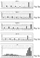
Fig. 5 a-e : eine schematische Darstellung von unterschiedlichen Subecho-kurven, die zu einer Echokurve zusammengefügt werden. -
Fig. 6 : eine Darstellung, wie anhand einer Echokurve, die erfindungsgemäß ermittelt wurde, der von einem Messsignal zurückgelegte Weg bestimmt wird.
-
1 : a schematic representation of the known transformation of a high-frequency signal into the low-frequency range, -
2 : a block diagram that illustrates the well-known functional principle of real-time sampling, -
3 : a block diagram that illustrates the functional principle of the method according to the invention, -
4 : schematic representations of echo curves obtained using the method according to the invention,- a) where an integer number of periods of the sampling frequency is greater by a predetermined time interval than a period of the transmission repetition frequency,
- b) where an integer number of periods of the sampling frequency is smaller by a predetermined time interval than a period duration of the transmission repetition frequency,
-
Fig. 5 ae : a schematic representation of different sub-echo curves that are combined to form an echo curve. -
6 1: an illustration of how the path covered by a measurement signal is determined using an echo curve that was determined according to the invention.
Die an der Oberfläche des Füllguts reflektierten Laserpulse werden nach einer von der Entfernung und daher vom Füllstand des Füllguts abhängigen Laufzeit in der Empfangseinheit 3 empfangen. Die empfangenen Laserpulse werden der Abtastschaltung 4, hier einem entsprechend ausgelegten schnellen AD Wandler, zugeführt, der die Laserpulse in Echtzeit abtastet. Die Abtastfrequenz ist um einen Faktor m größer als die von der Signalerzeugungseinheit 1 erzeugte Grundfrequenz f. Daher werden pro Laserpuls eine Vielzahl von Einzelwerten erfasst. Die Auswerteeinheit 5, hier ein Mikroprozessor, generiert anhand der in Echtzeit abgetasteten Laserpulse die Echokurve EK und ermittelt anhand der Echokurve EK den Füllstand des Füllguts in dem Behälter.The laser pulses reflected on the surface of the filling material are after a period dependent on the distance and therefore on the filling level of the filling
Die Laserpulse werden von der Sendeeinheit 2 in Richtung der Oberfläche des in
Die an der Oberfläche des Füllguts reflektierten Laserpulse werden nach einer von der Entfernung und daher vom Füllstand des Füllguts abhängigen Laufzeit in der Empfangseinheit 3 empfangen. Die empfangenen Laserpulse werden der Abtastschaltung 4, hier einem AD Wandler, zugeführt. Die Abtastung der Laserpulse erfolgt mit einer Abtastfrequenz fS , die sich geringfügig von der Grundfrequenz f unterscheidet. Die Abtastfrequenz wird von der Signalerzeugungseinheit 8, z.B. einem Oszillator, erzeugt. Die Differenzfrequenz fdiff zwischen Abtastfrequenz fS und Grundfrequenz f wird auf einen konstanten Betrag geregelt. Zahlenbeispiele wurden bereits an vorhergehender Stelle genannt. Ein Messzyklus wird von dem Mikroprozessor 5 nach einer Durchschwebung der Differenzfrequenz fdiff abgeschlossen, wenn also die Differenzfrequenz fdiff eine Periode T durchlaufen hat und die Grundfrequenz f und die Abtastfrequenz fS wieder in Phase sind.The laser pulses reflected on the surface of the filling material are received in the receiving
In Abhängigkeit von der gewünschten Auflösung bzw. Messgenauigkeit werden mehrere Subechokurven SEKx aufgenommen, wobei die Abtastwerte der einzelnen Subechokurven SEKx aufgrund der Grundfrequenz f , der Abtastfrequenz fS , der Differenzfrequenz fdiff und des Teilerfaktors TF jeweils zueinander um einen definiertes Zeitintervall Δt verschoben sind. Bevorzugt beträgt der Teilerfaktor TF 1/2n , mit n = 1, 2, 3, ... Hierdurch wird eine optimale Ausnutzung des Speichers, der dem Mikroprozessor 5 zugeordnet ist, sichergestellt. Zudem ist die Auswertung vereinfacht. Zeichnerisch dargestellt ist das Zuvorgesagte in den Figuren
Die Figuren
Erfindungsgemäß steht die Sendewiederholfrequenz f Pulse der Laserpulse in einer definierten Abhängigkeit zu der Abtastfrequenz fS , die auch als Samplefrequenz bezeichnet wird. Die definierte Abhängigkeit ist derart ausgeprägt, dass eine ganzzahlige Anzahl von Perioden der Abtastfrequenz fS um ein vorgegebenes Zeitintervall Td größer ist als eine Periodendauer der Sendewiederholfrequenz f Pulse. Dieser Fall ist in
In
Claims (11)
- Procedure for the laser-based determination of the level of a medium in a vessel according to a transit time procedure,wherein laser pulses of a predefined pulse width (Tp) are generated,wherein the laser pulses are emitted with a defined emission repeat frequency (f Pulse) in the direction of the surface of the medium,wherein the defined emission repeat frequency (f Pulse) of the laser pulses depends on a scan frequency (fS ) in such a way that a number of periods of the scan frequency (fS ) - said number being a whole number - is greater or less than a period duration of the emission repeat frequency (f Pulse) by a predefined time interval (Td ),wherein this time interval (Td ) is selected in such a way that it corresponds to a desired sample resolution and is less than the period duration of the scan frequency (fs ),wherein the laser pulses are received after reflection at the surface of the medium,wherein the laser pulses reflected at the surface of the medium are scanned with a scan frequency (fS ) in such a way that multiple scan values are recorded per laser pulse and are saved as a sub-echo curve (SEK),wherein the saved sub-echo curves (SEK) are compiled into a total echo curve (EK) after a measuring cycle,wherein the predefined dependence between the defined emission repeat frequency (f Pulse) and the scan frequency (fs ) is implemented by generating a basic frequency (f), which is greater than the emission repeat frequency (f Pulse), via a first frequency-generating component (1),wherein the emission repeat frequency (f Pulse) is obtained from the basic frequency (f) by multiplying by a predefined division factor (TF), andwherein the scan frequency (fS ) is generated by means of a second frequency-generating component (8),wherein a differential frequency (fdiff ) is generated on the basis of the basic frequency (f) and the scan frequency (fS ), wherein said differential frequency is regulated to a constant value,wherein multiple sub-echo curves (SEKx) are recorded depending on the desired resolution or measuring accuracy, wherein the scan values of the individual sub-echo curves (SEKx) are offset in relation to one another by a defined time interval (Δt) on the basis of the basic frequency (f), the scan frequency (fS ), the differential frequency (fdiff ) and the division factor (TF),wherein a measuring cycle is finished after the passage of the differential frequency (fdiff ) if the differential frequency (fdiff ) has passed through a period (T) and the basic frequency (f) and the scan frequency (fS ) are in phase again, andwherein the level is determined using the total echo curve (EK).
- Procedure as claimed in Claim 1,wherein a constant differential frequency between the emission repeat frequency (f Pulse) and the scan frequency (fS ) is regulated by means of a control circuit (5, 8), and the emission repeat frequency (f Pulse) and the scan frequency (fS ) are obtained directly from the frequencies (f Pulse , fs ) generated by the components (1, 8), orwherein the emission repeat frequency (f Pulse) and the scan frequency (fS ) are obtained indirectly by multiplying or dividing the two frequencies (f Pulse , fs ) generated by the components (1, 8).
- Procedure as claimed in Claim 1 or 2,
wherein the division factor is 1/2n (with n = 1, 2, 3, ...). - Procedure as claimed in Claim 1, 2 or 3,
wherein the basic frequency (f) and the scan frequency (fS ) of the laser pulses are in a frequency range from 100-200 MHz. - Procedure as claimed in Claim 1, 2, 3 or 4,
wherein the time interval for providing the level measured values is selected to satisfy, on the one hand, the requirements for the accuracy of the laser-based technology for application in level measuring technology and, on the other hand, to satisfy the safety demands of users of laser-based technology. - Procedure as claimed in Claim 5,
wherein the level measured values of a measuring cycle are provided in a time interval of less than 1 ms. - Procedure as claimed in one of the previous claims,
wherein the basic frequency (f) and the scan frequency (fS ) are used directly to form the difference (fdiff = f -fs ). - Laser-based unit, designed to determine the level of a medium in a vessel according to a transit time procedure as claimed in at least one of the previous claims,with a signal generation unit (1), which is designed to generate laser pulses with a predefined pulse width (Tp),with a transmission unit (2), which is designed to emit laser pulses with a defined emission repeat frequency (f Pulse) in the direction of the surface of the medium, wherein the defined emission repeat frequency (f Pulse) of the laser pulses is obtained by multiplying a predefined basic frequency (f) by a division factor (TF), orwherein the basic frequency is obtained by multiplying a defined emission repeat frequency (f Pulse) by a predefined factor,with a reception unit (3), which is designed to receive the laser pulses following reflection at the surface of the medium,with a first frequency-generating component (1), which is designed to generate the basic frequency (f) which is greater than the emission repeat frequency (f Pulse ),with a second frequency-generating component (8), which is designed to generate a scan frequency (fS ) which deviates slightly from the basic frequency (f), wherein a differential frequency (fdiff ) between the basic frequency (f) and the scan frequency (fS ) is regulated to a constant value,wherein the defined emission repeat frequency (f Pulse) of the laser pulses depends on the scan frequency (fS ) in such a way that a number of periods of the scan frequency (fS ) - said number being a whole number - is greater or smaller than a period duration of the emission repeat frequency (f Pulse) by a predefined time interval (Td ), andwherein said time interval (Td ) is selected in such a way that it corresponds to a desired sample resolution and is smaller than the period duration of the scan frequency (fs ),with a scan circuit (4), which is designed to scan the laser pulses reflected at the surface of the medium with the scan frequency (fS ) in such a way that several scan values are detected per laser pulse and are saved in each case as a sub-echo curve (SEK),wherein the scan values of the individual sub-echo curves (SEKx) are offset in relation to one another by a defined time interval (Δt) due to the basic frequency (f), the scan frequency (fS ), the differential frequency (fdiff ) and the division factor (TF),wherein a measuring cycle is completed after the passage of the differential frequency (fdiff ) if the differential frequency (fdiff ) has passed a period (T) and the basic frequency (f) and the scan frequency (fS ) are in phase again,andwith an evaluation unit (5) that is designed to compile the saved sub-echo curves (SEK) into a total echo curve (EK) following a measuring cycle and to determine the level of the medium in the vessel using the total echo curve (EK).
- Apparatus as claimed in Claim 8,
wherein the scan circuit (4) is an analog/digital converter and the evaluation unit (5) is a microprocessor. - Apparatus as claimed in Claim 8 or 9,
wherein the predefined pulse width (Tp) of the laser pulses is preferably between 1 ns and 10 ns. - Apparatus as claimed in one or more of the Claims 8 to 10,
wherein the division factor (TF) is 1/2n where n = 1, 2, 3, ...
Applications Claiming Priority (2)
| Application Number | Priority Date | Filing Date | Title |
|---|---|---|---|
| DE102012106149.1A DE102012106149A1 (en) | 2012-07-09 | 2012-07-09 | Method and device for the laser-based determination of the filling level of a filling material in a container |
| PCT/EP2013/061805 WO2014009068A1 (en) | 2012-07-09 | 2013-06-07 | Method and apparatus for the laser-based determination of the filling level of a filling material in a container |
Publications (2)
| Publication Number | Publication Date |
|---|---|
| EP2870438A1 EP2870438A1 (en) | 2015-05-13 |
| EP2870438B1 true EP2870438B1 (en) | 2022-05-11 |
Family
ID=48628639
Family Applications (1)
| Application Number | Title | Priority Date | Filing Date |
|---|---|---|---|
| EP13729299.1A Active EP2870438B1 (en) | 2012-07-09 | 2013-06-07 | Method and apparatus for the laser-based determination of the filling level of a filling material in a container |
Country Status (4)
| Country | Link |
|---|---|
| EP (1) | EP2870438B1 (en) |
| CN (1) | CN104471358A (en) |
| DE (1) | DE102012106149A1 (en) |
| WO (1) | WO2014009068A1 (en) |
Families Citing this family (7)
| Publication number | Priority date | Publication date | Assignee | Title |
|---|---|---|---|---|
| DE102012108460A1 (en) | 2012-09-11 | 2014-03-13 | Endress + Hauser Gmbh + Co. Kg | Method for laser-based determination of medium and/or process characteristic of clear water in container, involves comparing form and parameters with predetermined form and parameters, and determining characteristic based on comparison |
| DE102012108462A1 (en) | 2012-09-11 | 2014-03-13 | Endress + Hauser Gmbh + Co. Kg | Method for laser-based determination of level of liquid filling material in container used in e.g. chemical industry, involves scanning reflected pulses received from surface of material, after emitting laser pulses toward material |
| DE102013114737A1 (en) | 2013-12-20 | 2015-06-25 | Endress + Hauser Gmbh + Co. Kg | Laser-based level measuring device |
| CN107462302B (en) * | 2017-08-02 | 2019-06-21 | 浙江中产科技有限公司 | A kind of method of laser material position data processing |
| CN107907184B (en) * | 2017-12-01 | 2019-08-02 | 浙江中产科技有限公司 | A method of using two kinds of wavelength laser conjunction measuring material position distances |
| US11079268B2 (en) | 2017-12-21 | 2021-08-03 | Rosemount Inc. | Precision ADC sampling clock for high accuracy wireless guided wave radar |
| EP3690480A1 (en) * | 2019-01-30 | 2020-08-05 | Silicon Austria Labs GmbH | Method for time of flight measurement of pulses |
Family Cites Families (11)
| Publication number | Priority date | Publication date | Assignee | Title |
|---|---|---|---|---|
| DE2908854C2 (en) * | 1979-03-07 | 1986-04-17 | Endress U. Hauser Gmbh U. Co, 7867 Maulburg | Distance measuring device based on the pulse time-of-flight method |
| EP0348898B1 (en) * | 1988-06-29 | 1996-03-20 | Kabushiki Kaisha TOPCON | High resolution measuring device for time difference |
| DE59814044D1 (en) * | 1998-05-05 | 2007-08-09 | Endress & Hauser Gmbh & Co Kg | Microwave level gauge |
| DE19961855B4 (en) * | 1999-12-22 | 2007-11-29 | Endress + Hauser Gmbh + Co. Kg | Method and device for determining the fill level of a product in a container |
| DE10106681A1 (en) * | 2001-02-14 | 2003-01-02 | Endress & Hauser Gmbh & Co Kg | Device for determining the fill level of a product in a container |
| EP1576385A2 (en) * | 2002-11-26 | 2005-09-21 | James F. Munro | An apparatus for high accuracy distance and velocity measurement and methods thereof |
| US7412337B2 (en) * | 2005-10-13 | 2008-08-12 | Endress + Hauser Gmbh + Co. Kg | Method for determining fill level on the basis of travel time of a high-frequency measuring signal |
| EP1882959A1 (en) * | 2006-07-17 | 2008-01-30 | Leica Geosystems AG | Optical distance measuring method and corresponding optical range finder |
| US7640122B2 (en) * | 2007-11-07 | 2009-12-29 | Institut National D'optique | Digital signal processing in optical systems used for ranging applications |
| EP2235561B8 (en) * | 2007-12-21 | 2017-05-31 | Leddartech Inc. | Detection and ranging methods and systems |
| EP2265909B8 (en) * | 2008-04-04 | 2017-07-26 | Leddartech Inc. | Optical level measurement device and method |
-
2012
- 2012-07-09 DE DE102012106149.1A patent/DE102012106149A1/en not_active Withdrawn
-
2013
- 2013-06-07 CN CN201380036697.1A patent/CN104471358A/en active Pending
- 2013-06-07 EP EP13729299.1A patent/EP2870438B1/en active Active
- 2013-06-07 WO PCT/EP2013/061805 patent/WO2014009068A1/en active Application Filing
Also Published As
| Publication number | Publication date |
|---|---|
| WO2014009068A1 (en) | 2014-01-16 |
| DE102012106149A1 (en) | 2014-01-09 |
| EP2870438A1 (en) | 2015-05-13 |
| CN104471358A (en) | 2015-03-25 |
Similar Documents
| Publication | Publication Date | Title |
|---|---|---|
| EP2870438B1 (en) | Method and apparatus for the laser-based determination of the filling level of a filling material in a container | |
| EP0834086B1 (en) | Fmcw distance measurement process | |
| EP2626722B1 (en) | Optoelectronic sensor and method for recording and determining the distance of an object | |
| EP0955527A1 (en) | Microwave level detector | |
| DE2008256C3 (en) | Laser distance measuring system with pulse compression of the echoes of frequency-modulated laser pulses | |
| DE3038961A1 (en) | DEVICE FOR DETERMINING DATA OF A SIGNAL SPREADING PATH, IN PARTICULAR MEASURING SYSTEM WORKING AFTER THE REFLECTOR PRINCIPLE | |
| EP0882956A2 (en) | Method for material level measurement in a container according to the radar principle | |
| DE4406865C2 (en) | Distance measuring device | |
| DE102012112985B3 (en) | Distance measuring opto-electronic sensor for detecting and determining distance of objects in monitoring region, has evaluation unit to determine correlation peak of correlation sequence and measured value for object distance | |
| DE102014209375A1 (en) | Multi-target laser rangefinder | |
| EP2315053A2 (en) | Method and device for measuring the receiving times of impulses | |
| WO2018172369A1 (en) | Lidar measuring device | |
| EP0427969B1 (en) | Pulse time of flight measurement device | |
| DE2723355C2 (en) | Method and arrangement for evaluating radar pulse trains | |
| DE2133497C3 (en) | Method and arrangement for correlation distance measurement by means of a pseudostochastic pulse sequence | |
| DE911663C (en) | Method for checking, in particular for determining the distance of objects according to the reflection principle by pulse-wise emission and re-reception of high-frequency oscillations | |
| EP0303156B1 (en) | Method for laser doppler anemometry | |
| EP2766742A1 (en) | Method and device for optically measuring distances over wide distance ranges | |
| DE3120274C2 (en) | Distance measuring device | |
| DE102008045366B4 (en) | Apparatus and method for speed measurement | |
| DE10149423B4 (en) | Method and device for measuring distances in optically opaque media | |
| DE3324341C2 (en) | Device for the precise determination of short transit times of electronically generated pulses | |
| DE10025968A1 (en) | Distance determining method by the echo delay time principle, involves comparing received transmitted signal component with a first threshold value and with a second threshold value, exceeding the first | |
| DE1773287B1 (en) | DEVICE FOR RADIOELECTRIC DISTANCE MEASUREMENT | |
| EP2881706B1 (en) | Method for measuring bodies of water |
Legal Events
| Date | Code | Title | Description |
|---|---|---|---|
| PUAI | Public reference made under article 153(3) epc to a published international application that has entered the european phase |
Free format text: ORIGINAL CODE: 0009012 |
|
| 17P | Request for examination filed |
Effective date: 20141210 |
|
| AK | Designated contracting states |
Kind code of ref document: A1 Designated state(s): AL AT BE BG CH CY CZ DE DK EE ES FI FR GB GR HR HU IE IS IT LI LT LU LV MC MK MT NL NO PL PT RO RS SE SI SK SM TR |
|
| AX | Request for extension of the european patent |
Extension state: BA ME |
|
| RIN1 | Information on inventor provided before grant (corrected) |
Inventor name: DAMM, HARTMUT Inventor name: SEILER, CHRISTIAN Inventor name: JIANG, MINGZHENG Inventor name: SCHLEIFERBOECK, JAN |
|
| DAX | Request for extension of the european patent (deleted) | ||
| RAP1 | Party data changed (applicant data changed or rights of an application transferred) |
Owner name: ENDRESS+HAUSER SE+CO. KG |
|
| STAA | Information on the status of an ep patent application or granted ep patent |
Free format text: STATUS: EXAMINATION IS IN PROGRESS |
|
| 17Q | First examination report despatched |
Effective date: 20181015 |
|
| STAA | Information on the status of an ep patent application or granted ep patent |
Free format text: STATUS: EXAMINATION IS IN PROGRESS |
|
| GRAP | Despatch of communication of intention to grant a patent |
Free format text: ORIGINAL CODE: EPIDOSNIGR1 |
|
| STAA | Information on the status of an ep patent application or granted ep patent |
Free format text: STATUS: GRANT OF PATENT IS INTENDED |
|
| INTG | Intention to grant announced |
Effective date: 20220110 |
|
| GRAS | Grant fee paid |
Free format text: ORIGINAL CODE: EPIDOSNIGR3 |
|
| GRAA | (expected) grant |
Free format text: ORIGINAL CODE: 0009210 |
|
| STAA | Information on the status of an ep patent application or granted ep patent |
Free format text: STATUS: THE PATENT HAS BEEN GRANTED |
|
| AK | Designated contracting states |
Kind code of ref document: B1 Designated state(s): AL AT BE BG CH CY CZ DE DK EE ES FI FR GB GR HR HU IE IS IT LI LT LU LV MC MK MT NL NO PL PT RO RS SE SI SK SM TR |
|
| REG | Reference to a national code |
Ref country code: GB Ref legal event code: FG4D Free format text: NOT ENGLISH |
|
| REG | Reference to a national code |
Ref country code: CH Ref legal event code: EP |
|
| REG | Reference to a national code |
Ref country code: AT Ref legal event code: REF Ref document number: 1491789 Country of ref document: AT Kind code of ref document: T Effective date: 20220515 |
|
| REG | Reference to a national code |
Ref country code: DE Ref legal event code: R096 Ref document number: 502013016142 Country of ref document: DE |
|
| REG | Reference to a national code |
Ref country code: IE Ref legal event code: FG4D Free format text: LANGUAGE OF EP DOCUMENT: GERMAN |
|
| REG | Reference to a national code |
Ref country code: LT Ref legal event code: MG9D |
|
| REG | Reference to a national code |
Ref country code: NL Ref legal event code: MP Effective date: 20220511 |
|
| PG25 | Lapsed in a contracting state [announced via postgrant information from national office to epo] |
Ref country code: SE Free format text: LAPSE BECAUSE OF FAILURE TO SUBMIT A TRANSLATION OF THE DESCRIPTION OR TO PAY THE FEE WITHIN THE PRESCRIBED TIME-LIMIT Effective date: 20220511 Ref country code: PT Free format text: LAPSE BECAUSE OF FAILURE TO SUBMIT A TRANSLATION OF THE DESCRIPTION OR TO PAY THE FEE WITHIN THE PRESCRIBED TIME-LIMIT Effective date: 20220912 Ref country code: NO Free format text: LAPSE BECAUSE OF FAILURE TO SUBMIT A TRANSLATION OF THE DESCRIPTION OR TO PAY THE FEE WITHIN THE PRESCRIBED TIME-LIMIT Effective date: 20220811 Ref country code: NL Free format text: LAPSE BECAUSE OF FAILURE TO SUBMIT A TRANSLATION OF THE DESCRIPTION OR TO PAY THE FEE WITHIN THE PRESCRIBED TIME-LIMIT Effective date: 20220511 Ref country code: LT Free format text: LAPSE BECAUSE OF FAILURE TO SUBMIT A TRANSLATION OF THE DESCRIPTION OR TO PAY THE FEE WITHIN THE PRESCRIBED TIME-LIMIT Effective date: 20220511 Ref country code: HR Free format text: LAPSE BECAUSE OF FAILURE TO SUBMIT A TRANSLATION OF THE DESCRIPTION OR TO PAY THE FEE WITHIN THE PRESCRIBED TIME-LIMIT Effective date: 20220511 Ref country code: GR Free format text: LAPSE BECAUSE OF FAILURE TO SUBMIT A TRANSLATION OF THE DESCRIPTION OR TO PAY THE FEE WITHIN THE PRESCRIBED TIME-LIMIT Effective date: 20220812 Ref country code: FI Free format text: LAPSE BECAUSE OF FAILURE TO SUBMIT A TRANSLATION OF THE DESCRIPTION OR TO PAY THE FEE WITHIN THE PRESCRIBED TIME-LIMIT Effective date: 20220511 Ref country code: ES Free format text: LAPSE BECAUSE OF FAILURE TO SUBMIT A TRANSLATION OF THE DESCRIPTION OR TO PAY THE FEE WITHIN THE PRESCRIBED TIME-LIMIT Effective date: 20220511 Ref country code: BG Free format text: LAPSE BECAUSE OF FAILURE TO SUBMIT A TRANSLATION OF THE DESCRIPTION OR TO PAY THE FEE WITHIN THE PRESCRIBED TIME-LIMIT Effective date: 20220811 |
|
| PG25 | Lapsed in a contracting state [announced via postgrant information from national office to epo] |
Ref country code: RS Free format text: LAPSE BECAUSE OF FAILURE TO SUBMIT A TRANSLATION OF THE DESCRIPTION OR TO PAY THE FEE WITHIN THE PRESCRIBED TIME-LIMIT Effective date: 20220511 Ref country code: PL Free format text: LAPSE BECAUSE OF FAILURE TO SUBMIT A TRANSLATION OF THE DESCRIPTION OR TO PAY THE FEE WITHIN THE PRESCRIBED TIME-LIMIT Effective date: 20220511 Ref country code: LV Free format text: LAPSE BECAUSE OF FAILURE TO SUBMIT A TRANSLATION OF THE DESCRIPTION OR TO PAY THE FEE WITHIN THE PRESCRIBED TIME-LIMIT Effective date: 20220511 Ref country code: IS Free format text: LAPSE BECAUSE OF FAILURE TO SUBMIT A TRANSLATION OF THE DESCRIPTION OR TO PAY THE FEE WITHIN THE PRESCRIBED TIME-LIMIT Effective date: 20220911 |
|
| PG25 | Lapsed in a contracting state [announced via postgrant information from national office to epo] |
Ref country code: SM Free format text: LAPSE BECAUSE OF FAILURE TO SUBMIT A TRANSLATION OF THE DESCRIPTION OR TO PAY THE FEE WITHIN THE PRESCRIBED TIME-LIMIT Effective date: 20220511 Ref country code: SK Free format text: LAPSE BECAUSE OF FAILURE TO SUBMIT A TRANSLATION OF THE DESCRIPTION OR TO PAY THE FEE WITHIN THE PRESCRIBED TIME-LIMIT Effective date: 20220511 Ref country code: RO Free format text: LAPSE BECAUSE OF FAILURE TO SUBMIT A TRANSLATION OF THE DESCRIPTION OR TO PAY THE FEE WITHIN THE PRESCRIBED TIME-LIMIT Effective date: 20220511 Ref country code: EE Free format text: LAPSE BECAUSE OF FAILURE TO SUBMIT A TRANSLATION OF THE DESCRIPTION OR TO PAY THE FEE WITHIN THE PRESCRIBED TIME-LIMIT Effective date: 20220511 Ref country code: DK Free format text: LAPSE BECAUSE OF FAILURE TO SUBMIT A TRANSLATION OF THE DESCRIPTION OR TO PAY THE FEE WITHIN THE PRESCRIBED TIME-LIMIT Effective date: 20220511 Ref country code: CZ Free format text: LAPSE BECAUSE OF FAILURE TO SUBMIT A TRANSLATION OF THE DESCRIPTION OR TO PAY THE FEE WITHIN THE PRESCRIBED TIME-LIMIT Effective date: 20220511 |
|
| REG | Reference to a national code |
Ref country code: CH Ref legal event code: PL |
|
| REG | Reference to a national code |
Ref country code: DE Ref legal event code: R097 Ref document number: 502013016142 Country of ref document: DE |
|
| REG | Reference to a national code |
Ref country code: BE Ref legal event code: MM Effective date: 20220630 |
|
| PG25 | Lapsed in a contracting state [announced via postgrant information from national office to epo] |
Ref country code: MC Free format text: LAPSE BECAUSE OF FAILURE TO SUBMIT A TRANSLATION OF THE DESCRIPTION OR TO PAY THE FEE WITHIN THE PRESCRIBED TIME-LIMIT Effective date: 20220511 |
|
| PLBE | No opposition filed within time limit |
Free format text: ORIGINAL CODE: 0009261 |
|
| STAA | Information on the status of an ep patent application or granted ep patent |
Free format text: STATUS: NO OPPOSITION FILED WITHIN TIME LIMIT |
|
| PG25 | Lapsed in a contracting state [announced via postgrant information from national office to epo] |
Ref country code: AL Free format text: LAPSE BECAUSE OF FAILURE TO SUBMIT A TRANSLATION OF THE DESCRIPTION OR TO PAY THE FEE WITHIN THE PRESCRIBED TIME-LIMIT Effective date: 20220511 |
|
| 26N | No opposition filed |
Effective date: 20230214 |
|
| GBPC | Gb: european patent ceased through non-payment of renewal fee |
Effective date: 20220811 |
|
| PG25 | Lapsed in a contracting state [announced via postgrant information from national office to epo] |
Ref country code: LU Free format text: LAPSE BECAUSE OF NON-PAYMENT OF DUE FEES Effective date: 20220607 Ref country code: LI Free format text: LAPSE BECAUSE OF NON-PAYMENT OF DUE FEES Effective date: 20220630 Ref country code: IE Free format text: LAPSE BECAUSE OF NON-PAYMENT OF DUE FEES Effective date: 20220607 Ref country code: FR Free format text: LAPSE BECAUSE OF NON-PAYMENT OF DUE FEES Effective date: 20220711 Ref country code: CH Free format text: LAPSE BECAUSE OF NON-PAYMENT OF DUE FEES Effective date: 20220630 |
|
| PG25 | Lapsed in a contracting state [announced via postgrant information from national office to epo] |
Ref country code: SI Free format text: LAPSE BECAUSE OF FAILURE TO SUBMIT A TRANSLATION OF THE DESCRIPTION OR TO PAY THE FEE WITHIN THE PRESCRIBED TIME-LIMIT Effective date: 20220511 Ref country code: BE Free format text: LAPSE BECAUSE OF NON-PAYMENT OF DUE FEES Effective date: 20220630 |
|
| P01 | Opt-out of the competence of the unified patent court (upc) registered |
Effective date: 20230601 |
|
| PGFP | Annual fee paid to national office [announced via postgrant information from national office to epo] |
Ref country code: DE Payment date: 20230620 Year of fee payment: 11 |
|
| REG | Reference to a national code |
Ref country code: AT Ref legal event code: MM01 Ref document number: 1491789 Country of ref document: AT Kind code of ref document: T Effective date: 20220607 |
|
| PG25 | Lapsed in a contracting state [announced via postgrant information from national office to epo] |
Ref country code: GB Free format text: LAPSE BECAUSE OF NON-PAYMENT OF DUE FEES Effective date: 20220811 Ref country code: AT Free format text: LAPSE BECAUSE OF NON-PAYMENT OF DUE FEES Effective date: 20220607 |
|
| PG25 | Lapsed in a contracting state [announced via postgrant information from national office to epo] |
Ref country code: IT Free format text: LAPSE BECAUSE OF FAILURE TO SUBMIT A TRANSLATION OF THE DESCRIPTION OR TO PAY THE FEE WITHIN THE PRESCRIBED TIME-LIMIT Effective date: 20220511 |
|
| PG25 | Lapsed in a contracting state [announced via postgrant information from national office to epo] |
Ref country code: HU Free format text: LAPSE BECAUSE OF FAILURE TO SUBMIT A TRANSLATION OF THE DESCRIPTION OR TO PAY THE FEE WITHIN THE PRESCRIBED TIME-LIMIT; INVALID AB INITIO Effective date: 20130607 |