EP0427969B1 - Pulse time of flight measurement device - Google Patents
Pulse time of flight measurement device Download PDFInfo
- Publication number
- EP0427969B1 EP0427969B1 EP90119867A EP90119867A EP0427969B1 EP 0427969 B1 EP0427969 B1 EP 0427969B1 EP 90119867 A EP90119867 A EP 90119867A EP 90119867 A EP90119867 A EP 90119867A EP 0427969 B1 EP0427969 B1 EP 0427969B1
- Authority
- EP
- European Patent Office
- Prior art keywords
- pulse
- transit time
- digital converter
- measuring arrangement
- time measuring
- Prior art date
- Legal status (The legal status is an assumption and is not a legal conclusion. Google has not performed a legal analysis and makes no representation as to the accuracy of the status listed.)
- Expired - Lifetime
Links
Images


Classifications
-
- G—PHYSICS
- G01—MEASURING; TESTING
- G01S—RADIO DIRECTION-FINDING; RADIO NAVIGATION; DETERMINING DISTANCE OR VELOCITY BY USE OF RADIO WAVES; LOCATING OR PRESENCE-DETECTING BY USE OF THE REFLECTION OR RERADIATION OF RADIO WAVES; ANALOGOUS ARRANGEMENTS USING OTHER WAVES
- G01S13/00—Systems using the reflection or reradiation of radio waves, e.g. radar systems; Analogous systems using reflection or reradiation of waves whose nature or wavelength is irrelevant or unspecified
- G01S13/02—Systems using reflection of radio waves, e.g. primary radar systems; Analogous systems
- G01S13/06—Systems determining position data of a target
- G01S13/08—Systems for measuring distance only
- G01S13/10—Systems for measuring distance only using transmission of interrupted, pulse modulated waves
- G01S13/103—Systems for measuring distance only using transmission of interrupted, pulse modulated waves particularities of the measurement of the distance
-
- G—PHYSICS
- G01—MEASURING; TESTING
- G01S—RADIO DIRECTION-FINDING; RADIO NAVIGATION; DETERMINING DISTANCE OR VELOCITY BY USE OF RADIO WAVES; LOCATING OR PRESENCE-DETECTING BY USE OF THE REFLECTION OR RERADIATION OF RADIO WAVES; ANALOGOUS ARRANGEMENTS USING OTHER WAVES
- G01S17/00—Systems using the reflection or reradiation of electromagnetic waves other than radio waves, e.g. lidar systems
- G01S17/02—Systems using the reflection of electromagnetic waves other than radio waves
- G01S17/06—Systems determining position data of a target
- G01S17/08—Systems determining position data of a target for measuring distance only
- G01S17/10—Systems determining position data of a target for measuring distance only using transmission of interrupted, pulse-modulated waves
Definitions
- the invention relates to a pulse transit time measuring arrangement according to the preamble of claim 1.
- Such a pulse transit time measuring arrangement is known from DE-A 36 20 226. It is particularly suitable for laser range finders with low transmission pulse energy for measurements on distant, small, weakly reflecting objects.
- the received pulses are very weak and are sometimes smaller than noise signals occurring in the arrangement.
- the analog-to-digital converter and the parallel adder can therefore be designed with a small number of bits, as a result of which the necessary processing speed can be easily achieved and the circuit complexity is kept low.
- the analog-digital converter is overdriven or, after a few added pulses, the parallel adder is overdriven. The result of this is that the maximum value of the respective output signal is reached over several sampling pulse intervals. The determination of the peak position is thereby undetermined.
- a differentiator is continuously switched on in the digital processing of received pulses.
- delta modulation Something similar is known as delta modulation and is used, for example, in the field of speech recognition.
- Figures 2 through 6 are the result of computer simulations.
- FIGS. 3 to 6 impulses of predetermined shape and amplitude with statistical noise predetermined average amplitude were superimposed and the processing steps described below for FIGS. 3 to 6 were simulated. This serves to make it easier to understand and takes into account the difficulty in deriving the very fast low-energy signals from the complex arrangement without interference.
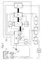
- the light pulse transmitter 1 first shows a light pulse transmitter 1, a light reflecting object 2 and a light receiver 3, which form an optical pulse transit time measuring section.
- the light pulse transmitter 1 consists, for. B. from a GaAs laser diode with power supply, pulse shaping in the nanosecond range and stabilization.
- Object 2 is shown as a triple mirror, i.e. as a cooperative element.
- the invention finds particularly advantageous application in any diffusely reflecting objects, such as machine parts, buildings, etc.
- Light pulse transmitter 1 and light receiver 3 generally also contain optics for determining a suitable geometry of the transmitted and received light bundles.
- a capacitor 4 suppresses constant light components by capacitive signal coupling.
- an electrical signal which contains the transit time and intensity of the received light pulse and an independent noise component.
- the signal is fed to an n-bit analog-digital converter 6 via an amplifier 5.
- the analog-digital converter 6 preferably has a low number of bits, in particular only 1 bit.
- the digital signal B from the output of the analog-digital converter 6 is fed to a parallel adder 7.
- a trigger pulse generator 8 with a pulse rate in the kilohertz range controls the light pulse transmitter 1, the parallel adder 7 and an evaluation circuit 10, which will be described below.
- a sampling pulse generator 9 with a pulse rate in the megahertz range generates the operating clock of the analog-digital converter 6 and the parallel adder 7 and gives the time standard for the evaluation circuit 10.
- the parallel adder 7 has a number of channels which is sufficient to fully capture the receive pulse for the largest and smallest range of the arrangement.
- the number of channels is therefore greater than the product of the greatest transit time and frequency of the sampling pulse generator 9.
- the evaluation device 10 determines from the data field C at the output of the parallel adder 7 the transit time of the light pulse or the distance between the receiver 3 and object 2 and forwards this to a measured value display 12, a measured value memory 13 and / or a processing device 14.
- the evaluation device 10 can easily determine the pulse transit time from the channel with the maximum signal amplitude.
- the correlation with a target data field for the pulse shape is preferred.
- interpolation with a suitable information function reflecting the expected pulse shape can also be used.
- a device 11 is provided for making this target data field available. This can be digital storage.
- the device 11 can, however, also be connected via a transmitter 15 to a light pulse transmitter 1 and derive a desired data field from a transmission pulse for each measurement.
- the transmitter 15 can consist of a short light guide and a device corresponding to the parts 3, 4, 5 and 6.
- Figures 2a, 3a and 4a show that with a large measuring distance, in particular in the case of non-cooperative targets, received signals occurring at point A in FIG. 1 with a poor signal / noise ratio (FIG. 2a) at point C at the output of the Parallel adder 7 (Fig. 4a) can be significantly improved, although this does not look like this after the analog-digital converter 6 at point B in Fig. 1 (Fig. 3a).
- FIG. 2a signal / noise ratio
- Figures 2b, 3b and 4b each show the same as Figures 2a, 3a and 4a, but for received signals with a high signal-to-noise ratio, such as occur with a short measuring distance.
- a high signal-to-noise ratio such as occur with a short measuring distance.
- an overflow and a deterioration in the position determination of the maximum then occur due to the limited number of bits.
- the arrangement is expanded by a logic element 20 and a differentiating element 21.
- Both elements 20, 21 are connected between the capacitor 4 and the analog-digital converter 6, preferably in front of the amplifier 5.
- the logic element 20 is a self-holding threshold switch which, as long as the received signal at point A does not exceed a certain threshold value, switches a direct connection from point A to amplifier 5, as a result of which the entire arrangement functions as described above. If the threshold value is exceeded, the logic element 20 switches the differentiating element 21 into the signal line from point A to amplifier 5 and maintains this switching state. The effect achieved thereby is shown in FIGS. 5a / b and 6a / b.
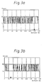
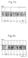
- the signal curve of FIG. 5b results at position B after the analog-digital converter 6 instead of the signal curve of FIG. 3b.
- FIG. 6b results.
- the action of the differentiating element 21 has turned the maximum of the input signal A (FIG. 2b) into a steep passage through the mean value of the noise, the position of which can be determined very precisely.
- the differentiating element 21 must, however, be switched off again from the signal processing by the logic element 20 if the input signal has only a small amplitude at a great distance.
- the input signal of FIG. 2a leads with the differentiator 21 switched on to the signal curves of FIG. 5a at point B after the analog-digital converter 6 and of FIG. 6a at point C after the parallel adder 7.
- the combination of the logic element 20 with the differentiating element 21 introduced according to the invention thus has the effect that both large and small input signals are optimally evaluated.
- the evaluation device 10 Compared to the known design, the evaluation device 10 must be designed such that, when the differentiating element 21 is switched on, it determines the channel in which there is a basic level corresponding to the mean value of the noise between two extremes of the signal C summed in the parallel adder 7, different from the noise. If the evaluation device 10 works according to a correlation method or with interpolation, nothing needs to be changed or switched over to it, only the device 11 must provide a target data field corresponding to a differentiated signal or such an interpolation function.
- the evaluation device 10 or the device 11 is switched over by the logic element 20 simultaneously with the switching of the differentiating element 21.
- the dynamic range of the analog-digital converter 6 is advantageously designed so that it is greater than the mean value of the noise at its input (point A, Fig. 1), and that the digitization step size is so large that the noise in statistical mean half results in the value zero of the output signal.
- the mean value of the noise in the output signal is 0.5.
- the threshold value of the logic element 20 is set for optimal use of the two signal evaluation methods with and without differentiation at a signal amplitude that is in the range of two to ten times the mean amplitude of the noise (at point C).
- the number of bits in the analog-digital converter 6 must be taken into account.
- the analog-digital converter 6 can be connected to the logic element 20 and have an additional n + 1 bit, which is not passed on to the parallel adder 7, and when the input signal sets it, the logic element 20 the differentiator 21 turns on.
- the differentiating element 21 can simply be designed as an RC element at the input of the amplifier 5, as a result of which a differentiating amplifier is formed.
- the differentiator 21 does not need to perform exact differentiation since the signal from the analog-digital converter 6 is broken down into only a few bits.
- the logic element 20 also switches the sampling pulse generator 9 to an increased pulse rate simultaneously with the switching on of the differentiating element 21.
- the parallel adder 7 with a certain number of channels is thus well used for the light pulses with a short transit time by stretching the time scale (transit time per channel), so that a further improvement in the measurement accuracy is achieved.
- the holding period for a switching state of the logic element 20 can be set as a fixed value, e.g. B. for the duration of 50 light pulses. It is more advantageous if the evaluation device 10 continuously evaluates the output signal of the parallel adder 7 and determines a measure of the uncertainty of the transit time or distance value caused by the noise and compares this measure with an intended target value. If the value falls below this target value, the measured value is output to the measured value display 12, the measured value memory 13 and / or the processing device 14.
- the parallel adder 7 is reset to zero and the held switching state of the logic element 20 is released, so that the next input signal pulse is compared again with the threshold value.
- the measuring arrangement can be constructed in various technologies with conventional components, with the greatest possible integration being advantageous.
- amplifiers 5 OP
- Analog-digital converter 6 parallel adders 7 and pulse generators 8.9 as IC's commercially available. You only have to pay attention to the suitability for the required high frequencies (approx. 100 MHz).
- a microprocessor 22 of suitable clock frequency is preferably programmed such that it contains all elements 5 to 11 and 20, 21, that is to say, apart from transmitter 1 and receiver 3 and measured value display 12 etc., the entire core of the pulse transit time measuring arrangement.
- the transit time of the light pulses from transmitter 1 via object 2 to receiver 3 specifies the necessary time scale for data processing.
Abstract
Description
Die Erfindung betrifft eine Impulslaufzeitmeßanordnung nach dem Oberbegriff des Anspruchs 1.The invention relates to a pulse transit time measuring arrangement according to the preamble of claim 1.
Eine derartige Impulslaufzeitmeßanordnung ist aus der DE-A 36 20 226 bekannt. Sie eignet sich besonders für Laserentfernungsmesser geringer Sendeimpuls-Energie zur Messung an entfernten, kleinen, schwach reflektierenden Objekten.Such a pulse transit time measuring arrangement is known from DE-A 36 20 226. It is particularly suitable for laser range finders with low transmission pulse energy for measurements on distant, small, weakly reflecting objects.
Unter solchen Umständen sind die empfangenen Impulse sehr schwach und sind teilweise kleiner als in der Anordnung auftretende Rauschsignale. Der Analog-Digital-Wandler und der Parallel-Addierer können daher mit geringer Bitzahl ausgeführt werden, wodurch die nötige Verarbeitungsgeschwindigkeit einfach erreichbar wird und der Schaltungsaufwand gering gehalten wird.Under such circumstances, the received pulses are very weak and are sometimes smaller than noise signals occurring in the arrangement. The analog-to-digital converter and the parallel adder can therefore be designed with a small number of bits, as a result of which the necessary processing speed can be easily achieved and the circuit complexity is kept low.
Treten durch nahe oder stark reflektierende Objekte hohe empfangene Impulse auf, so wird der Analog-Digital-Wandler oder nach wenigen aufaddierten Impulsen der Parallel-Addierer übersteuert. Das hat zur Folge, daß der Maximalwert des jeweiligen Ausgangssignals über mehrere Abtastimpulsintervalle hinweg erreicht wird. Die Peaklagenbestimmung wird dadurch unbestimmt.If high received pulses occur due to objects that are close or highly reflective, the analog-digital converter is overdriven or, after a few added pulses, the parallel adder is overdriven. The result of this is that the maximum value of the respective output signal is reached over several sampling pulse intervals. The determination of the peak position is thereby undetermined.
Bei einem Ziel-Ortungs- und Entfernungs-Meßsystem gemäß der DE 28 45 164 C2 ist bei der digitalen Verarbeitung von Empfangsimpulsen dauernd ein Differenzierer eingeschaltet.In a target location and distance measuring system according to DE 28 45 164 C2, a differentiator is continuously switched on in the digital processing of received pulses.
Es ist Aufgabe der vorliegenden Erfindung, eine gattungsgemäße Impulslaufzeitmeßanordnung so zu verändern, daß auch für große empfangene Impulse die Meßgenauigkeit nicht verschlechtert wird. Es ist eine weitere Aufgabe, die Meßgenauigkeit darüber hinaus zu verbessern.It is an object of the present invention to change a generic pulse transit time measuring arrangement in such a way that the measuring accuracy is not impaired even for large received pulses. Another task is to further improve the measurement accuracy.
Diese Aufgabe wird gelöst durch die Ausstattung einer gattungsgemäßen Impulslaufzeitmeßanordnung mit den kennzeichnenden Merkmalen des Anspruchs 1.
Weitere vorteilhafte Ausgestaltungen sind Gegenstand der Unteransprüche 2 bis 10.This object is achieved by equipping a generic pulse transit time measuring arrangement with the characterizing features of claim 1.
Further advantageous embodiments are the subject of
Zur digitalen Darstellung eines differenzierten Signals werden nicht unbedingt weniger Bits benötigt als für das unveränderte Signal. Einem Maximum des unveränderten Signals entspricht aber ein Nulldurchgang zwischen zwei Extrema des differenzierten Signals, und dessen Lage und Bestimmtheit wird durch eine Übersteuerung des Analog-Digital-Wandlers nicht beeinflußt. Das macht sich die Erfindung zu nutze.Less digital bits are not necessarily required for the digital representation of a differentiated signal than for the unchanged signal. However, a maximum of the unchanged signal corresponds to a zero crossing between two extremes of the differentiated signal, and its position and certainty is not influenced by an overload of the analog-digital converter. That makes use of the invention.
Ähnliches ist als Deltamodulation bekannt und wird z.B. im Bereich der Spracherkennung angewendet.Something similar is known as delta modulation and is used, for example, in the field of speech recognition.
Im folgenden wird die Erfindung anhand der Zeichnung im Einzelnen dargestellt. Es zeigen:
- Fig. 1
- Ein Blockschaltbild der Impulslaufzeitmeßanordnung gemäß einem Beispiel.
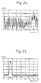
- Fig. 2
- Das analoge Laufzeitsignal eines Laser-Laufzeit-Entfernungsmessers (an der Stelle A der Fig. 1)
- a) für große Entfernung (140m)
- b) für kleine Entfernung (30m).
- Fig. 3
- Das Signal nach der Analog-Digital-Wandlung (Stelle B der Fig. 1), Differenzierglied ausgeschaltet
- a) für große Entfernung (140m)
- b) für kleine Entfernung (30m).
- Fig. 4 a/b
- Das Ausgangssignal des Parallel-Addierers (Stelle C in Fig. 1), Differenzierglied ausgeschaltet.
- Fig. 5 a/b
- Wie Fig. 3 a/b, jedoch Differenzierglied eingeschaltet.
- Fig. 6 a/b
- Wie Fig. 4 a/b, jedoch Differenzierglied eingeschaltet.
- Fig. 1
- A block diagram of the pulse delay measurement arrangement according to an example.
- Fig. 2
- The analog time-of-flight signal of a laser time-of-flight range finder (at point A in FIG. 1)
- a) for long distance (140m)
- b) for small distances (30m).
- Fig. 3
- The signal after the analog-digital conversion (point B of FIG. 1), differentiator switched off
- a) for long distance (140m)
- b) for small distances (30m).
- Fig. 4 a / b
- The output signal of the parallel adder (point C in Fig. 1), differentiator switched off.
- Fig. 5 a / b
- As Fig. 3 a / b, but differentiator switched on.
- Fig. 6 a / b
- As Fig. 4 a / b, but differentiator switched on.
Die Fig. 2 bis Fig. 6 sind das Ergebnis von Computersimulationen.Figures 2 through 6 are the result of computer simulations.
Dabei wurden (Fig. 2a/b) Impulse vorgegebener Form und Amplitude mit statistischem Rauschen vorgegebener mittlerer Amplitude überlagert und für die Fig. 3 bis 6 die im folgenden beschriebenen Verarbeitungsschritte simuliert. Dies dient der verständlicheren Darstellung und trägt der Schwierigkeit Rechnung, die sehr schnellen energiearmen Signale aus der komplexen Anordnung störungsfrei abzuleiten.Thereby (Fig. 2a / b) impulses of predetermined shape and amplitude with statistical noise predetermined average amplitude were superimposed and the processing steps described below for FIGS. 3 to 6 were simulated. This serves to make it easier to understand and takes into account the difficulty in deriving the very fast low-energy signals from the complex arrangement without interference.
Die Abszisse gibt den Objektabstand in Metern an. Über die Beziehung: Abstand = 1/2 x Lichtgeschwindigkeit x Laufzeit ist die Abstandsangabe der Laufzeit proportional.The abscissa indicates the object distance in meters. About the relationship: Distance = 1/2 x speed of light x runtime, the distance specification is proportional to the runtime.
Die Fig. 1 zeigt zunächst einen Lichtimpulssender 1, ein lichtreflektierendes Objekt 2 und einen Lichtempfänger 3, welche eine optische Impulslaufzeitmeßstrecke bilden. Der Lichtimpulssender 1 besteht z. B. aus einer GaAs-Laserdiode mit Stromversorgung, Pulsformung im Nanosekundenbereich und Stabilisierung. Das Objekt 2 ist als Tripelspiegel, also als kooperatives Element dargestellt. Die Erfindung findet aber besonders vorteilhafte Anwendung bei beliebigen, diffus reflektierenden Objekten, wie Maschinenteilen, Gebäuden usw.1 first shows a light pulse transmitter 1, a
Als Lichtempfänger 3 dient z. B. eine Avalanche-Photodiode mit Stromversorgung und Regelung des Arbeitsbereichs. Lichtimpulssender 1 und Lichtempfänger 3 enthalten in der Regel zudem Optiken zur Bestimmung einer geeigneten Geometrie der Sende- und Empfangslichtbündel. Ein Kondensator 4 unterdrückt durch kapazitive Signalauskopplung Gleichlichtanteile. An der Stelle A liegt dann ein elektrisches Signal vor, das Laufzeit und Intensität des empfangenden Lichtimpulses und einen davon unabhängigen Rauschanteil enthält.As a light receiver 3 z. B. an avalanche photodiode with power supply and control of the work area. Light pulse transmitter 1 and
Über einen Verstärker 5 wird das Signal einem n-Bit-Analog-Digital-Wandler 6 zugeführt. Der Analog-Digital-Wandler 6 hat vorzugsweise eine niedrige Bitzahl, insbesondere nur 1 Bit. Das digitale Signal B vom Ausgang des Analog-Digital-Wandlers 6 wird einem Parallel-Addierer 7 zugeführt.The signal is fed to an n-bit analog-digital converter 6 via an
Ein Triggerimpulsgenerator 8 mit einer Pulsrate im Kilohertzbereich steuert den Lichtimpulssender 1, den Parallel-Addierer 7 und eine Auswerteschaltung 10, welche weiter unten beschrieben wird.A
Ein Abtastimpulsgenerator 9 mit einer Pulsrate im Megahertzbereich erzeugt den Arbeitstakt des Analog-Digital-Wandlers 6 und des Parallel-Addierers 7 und gibt das Zeitnormal für die Auswerteschaltung 10.A
Der Parallel-Addierer 7 hat eine Anzahl von Kanälen, die ausreicht, den Empfangsimpuls für die größte und kleinste Reichweite der Anordnung voll zu erfassen. Die Anzahl von Kanälen ist also größer als das Produkt aus größter Laufzeit und Frequenz des Abtastimpulsgenerators 9.The
Die Auswerteeinrichtung 10 bestimmt aus dem Datenfeld C am Ausgang des Parallel-Addierers 7 die Laufzeit des Lichtimpulses bzw. den Abstand zwischen Empfänger 3 und Objekt 2 und gibt diese an eine Meßwertanzeige 12, einen Meßwertspeicher 13 und/oder eine Verarbeitungseinrichtung 14 weiter.The
Die Auswerteeinrichtung 10 kann die Impulslaufzeit einfach aus dem Kanal mit maximaler Signalamplitude bestimmen. Bevorzugt wird aber die Korrelation mit einem Soll-Datenfeld für die Impulsform. Alternativ kann auch Interpolation mit einer geeigneten, die erwartete Impulsform wiedergebenden Informationsfunktion eingesetzt werden. Dazu ist eine Einrichtung 11 zur Bereitstellung dieses Soll-Datenfeldes vorgesehen. Dies kann ein digitaler Speicher sein.The
Die Einrichtung 11 kann jedoch auch über einen Übertrager 15 mit einem Lichtimpulssender 1 verbunden sein und für jede Messung ein Soll-Datenfeld aus einem Sendeimpuls ableiten. Dazu kann der Übertrager 15 aus einem kurzen Lichtleiter und einer den Teilen 3,4,5 und 6 entsprechenden Einrichtung bestehen.The
Die soweit beschriebene Anordnung ist bekannt und entspricht der DE-A 36 20 226.The arrangement described so far is known and corresponds to DE-A 36 20 226.
Die Figuren 2a, 3a und 4a zeigen, daß damit bei großer Meßdistanz, insbesondere bei nicht kooperativen Zielen, an der Stelle A der Fig. 1 auftretende Empfangssignale mit schlechtem Signal/Rausch-Verhältnis (Fig. 2a) an der Stelle C am Ausgang des Parallel-Addierers 7 (Fig. 4a) deutlich verbessert werden , obwohl dies nach dem Analog-Digital-Wandler 6 an der Stelle B der Fig. 1 nicht so aussieht (Fig. 3a).Figures 2a, 3a and 4a show that with a large measuring distance, in particular in the case of non-cooperative targets, received signals occurring at point A in FIG. 1 with a poor signal / noise ratio (FIG. 2a) at point C at the output of the Parallel adder 7 (Fig. 4a) can be significantly improved, although this does not look like this after the analog-digital converter 6 at point B in Fig. 1 (Fig. 3a).
Die Figuren 2b, 3b und 4b zeigen jeweils das gleiche wie die Figuren 2a, 3a und 4a, aber für Empfangssignale mit hohem Signal/Rausch-Verhältnis, wie sie bei geringer Meßdistanz auftreten. Bei C am Ausgang des Parallel-Addierers 7 (Fig. 4b) tritt dann durch dessen beschränkte Bitzahl ein Überlauf und eine Verschlechterung der Lagebestimmung des Maximums auf.Figures 2b, 3b and 4b each show the same as Figures 2a, 3a and 4a, but for received signals with a high signal-to-noise ratio, such as occur with a short measuring distance. At C at the output of the parallel adder 7 (FIG. 4b) an overflow and a deterioration in the position determination of the maximum then occur due to the limited number of bits.
Dieses Problem führt zu der erfindungsgemäßen Weiterbildung der beschriebenen Impulslaufzeitmeßanordnung.This problem leads to the development according to the invention of the pulse transit time measuring arrangement described.
Dazu wird die Anordnung, wie in Fig. 1 gezeigt, um ein logisches Glied 20 und ein Differenzierglied 21 erweitert.For this purpose, as shown in FIG. 1, the arrangement is expanded by a
Beide Glieder 20, 21 sind zwischen den Kondensator 4 und den Analog-Digital-Wandler 6 geschaltet, und zwar vorzugsweise vor dem Verstärker 5.Both
Das logische Glied 20 ist ein selbsthaltender Schwellwertschalter, der, solange das Empfangssignal an der Stelle A einen bestimmten Schwellwert nicht überschreitet, eine direkte Verbindung von der Stelle A zu dem Verstärker 5 schaltet, wodurch die gesamte Anordnung wie oben beschrieben funktioniert. Wird der Schwellwert überschritten, dann schaltet das logische Glied 20 das Differenzierglied 21 in die Signalleitung von der Stelle A zum Verstärker 5 und hält diesen Schaltzustand. Die dadurch erzielte Wirkung zeigen die Figuren 5a/b und 6a/b.The
Für das Empfangssignal der Fig. 2b für kleine Entfernung mit hoher Amplitude und dagegen geringem Rauschen, ergibt sich an der Stelle B nach dem Analog-Digital-Wandler 6 statt dem Signalverlauf der Fig. 3b der Signalverlauf der Fig. 5b. An der Stelle C nach dem Parallel-Addierer 7 ergibt sich statt Fig. 4b die Fig. 6b.For the received signal of FIG. 2b for a small distance with a high amplitude and, on the other hand, low noise, the signal curve of FIG. 5b results at position B after the analog-digital converter 6 instead of the signal curve of FIG. 3b. At point C after the
In der Fig. 6b wurde durch die Wirkung des Differenzierglieds 21 aus dem Maximum des Eingangssignals A (Fig. 2b) ein steiler Durchgang durch den Mittelwert des Rauschens, dessen Lage sehr genau feststellbar ist.In FIG. 6b, the action of the differentiating
Ist in der vorbekannten Art für das Eingangssignal A nach Fig. 2b die Abstandsbestimmung verschlechtert worden, vgl. Fig. 4b, so ergibt sich durch Einschalten des Differenzierglieds 21 eine deutliche Verbesserung, vgl. Fig. 6b.If the distance determination has deteriorated in the previously known manner for the input signal A according to FIG. 2b, cf. 4b, there is a significant improvement by switching on the differentiating
Das Differenzierglied 21 muß jedoch durch das logische Glied 20 wieder aus der Signalverarbeitung ausgeschaltet werden, wenn das Eingangssignal bei großer Entfernung nur noch kleine Amplitude hat. Das Eingangssignal der Fig. 2a führt nämlich mit eingeschaltetem Differenzierglied 21 zu den Signalverläufen der Fig. 5a an der Stelle B nach dem Analog-Digital-Wandler 6 und der Fig. 6a an der Stelle C nach dem Parallel-Addierer 7.The differentiating
Der in Fig. 6a entstandene Durchgang durch den Mittelwert des Rauschens an der dem Maximum in Fig. 2a entsprechenden Stelle ist im Rauschen praktisch untergegangen.The passage in FIG. 6a through the mean value of the noise at the point corresponding to the maximum in FIG. 2a has practically disappeared in the noise.
Die erfindungsgemäß eingeführte Kombination des logischen Glieds 20 mit dem Differenzierglied 21 bewirkt also, daß sowohl große als auch kleine Eingangssignale optimal ausgewertet werden.The combination of the
Gegenüber der bekannten Ausführung muß die Auswerteeinrichtung 10 so ausgebildet werden, daß sie bei eingeschaltetem Differenzierglied 21 den Kanal bestimmt in dem ein dem Mittelwert des Rauschens entsprechender Grundpegel zwischen zwei vom Rauschen unterschiedenen Extrema des im Parallel-Addierer 7 aufsummierten Signals C vorliegt. Arbeitet die Auswerteeinrichtung 10 nach einem Korrelationsverfahren oder mit Interpolation, so muß an ihr dazu nichts geändert oder umgeschaltet werden, lediglich die Einrichtung 11 muß ein einem differenzierten Signal entsprechendes Soll-Datenfeld bzw. eine solche Interpolationsfunktion bereitstellen.Compared to the known design, the
Die Umschaltung der Auswerteeinrichtung 10 oder der Einrichtung 11 erfolgt durch das logische Glied 20 simultan mit der Schaltung des Differenzierglieds 21.The
Der dynamische Bereich des Analog-Digital-Wandlers 6 wird vorteilhaft so ausgelegt, daß er größer als der Betragsmittelwert des Rauschens an seinem Eingang (Stelle A, Fig. 1) ist, und daß die Digitalisierungs-Schrittweite so groß ist, daß das Rauschen im statistischen Mittel zur Hälfte den Wert Null des Ausgangssignals ergibt. In der Ausführung als 1-Bit-Analog-Digi-tal-Wandler ist dann der Mittelwert des Rauschens im Ausgangssig-nal 0,5.The dynamic range of the analog-digital converter 6 is advantageously designed so that it is greater than the mean value of the noise at its input (point A, Fig. 1), and that the digitization step size is so large that the noise in statistical mean half results in the value zero of the output signal. In the version as a 1-bit analog-digital converter, the mean value of the noise in the output signal is 0.5.
Der Schwellwert des logischen Glieds 20 wird zur optimalen Nutzung der beiden Signalauswerteverfahren mit und ohne Differentiation bei einer Signalamplitude gesetzt, die im Bereich des zwei- bis zehnfachen der mittleren Amplitude des Rauschens (an der Stelle C) liegt. Dabei ist die Bitzahl des Analog-Digital-Wandlers 6 zu berücksichtigen. Zur Festlegung der Schwelle kann der Analog-Digital-Wandler 6 mit dem logischen Glied 20 verbunden sein und ein zusätzliches n + 1 Bit aufweisen, das nicht an den Parallel-Addierer 7 weitergeleitet wird, und bei dessen Setzen durch das Eingangssignal das logische Glied 20 das Differenzierglied 21 einschaltet.The threshold value of the
Das Differenzierglied 21 kann einfach als RC-Glied am Eingang des Verstärkes 5 ausgebildet sein, wodurch ein Differenzierverstärker gebildet wird. Das Differenzierglied 21 braucht keine exakte Differentiation auszuführen, da das Signal von dem Analog-Digital-Wandler 6 nur in wenige Bits zerlegt wird.The differentiating
Es ist vorteilhaft, wenn das logische Glied 20 gleichzeitig mit dem Einschalten des Differenzierglieds 21 auch den Abtastimpulsgenerator 9 auf eine erhöhte Impulsrate umschaltet. Der Parallel-Addierer 7 mit einer bestimmten Anzahl von Kanälen wird so für die Lichtimpulse mit kurzer Laufzeit durch Strecken der Zeitskala (Laufzeit pro Kanal) gut ausgenutzt, so daß eine weitere Verbesserung der Meßgenauigkeit erreicht wird.It is advantageous if the
Die Haltedauer für einen Schaltzustand des logischen Glieds 20 kann als fester Wert eingestellt werden, z. B. auf die Dauer von 50 Lichtimpulsen. Vorteilhafter ist es, wenn die Auswerteeinrichtung 10 das Ausgangssignal des Parallel-Addierers 7 fortlaufend auswertet und ein Maß für die durch das Rauschen verursachte Unsicherheit des Laufzeit- bzw. Entfernungswerts bestimmt und dieses Maß mit einem vorgesehenen Sollwert vergleicht. Wird dieser Sollwert unterschritten, dann wird der Meßwert ausgegeben an die Meßwertanzeige 12, den Meßwertspeicher 13 und/oder die Verarbeitungseinrichtung 14.The holding period for a switching state of the
Gleichzeitig wird der Parallel-Addierer 7 auf Null zurückgesetzt und der gehaltene Schaltzustand des logischen Glieds 20 wird freigegeben, so daß der nächstfolgende Eingangssignalimpuls wieder mit dem Schwellwert verglichen wird.At the same time, the
Die Meßanordnung kann in verschiedener Technologie mit üblichen Bauelementen aufgebaut werden, wobei eine möglichst weitgehende Integration vorteilhaft ist. Beispielsweise sind Verstärker 5 (OP); Analog-Digital-Wandler 6, Parallel-Addierer 7 und Impulsgeneratoren 8,9 als IC's handelsüblich. Dabei muß nur auf die Eignung für die erforderlichen hohen Frequenzen (ca. 100 MHz) geachtet werden.The measuring arrangement can be constructed in various technologies with conventional components, with the greatest possible integration being advantageous. For example, amplifiers 5 (OP); Analog-digital converter 6,
Vorzugsweise wird ein Mikroprozessor 22 geeigneter Taktfrequenz so programmiert, daß er alle Elemente 5 bis 11 und 20,21 enthält, also außer Sender 1 und Empfänger 3 und Meßwertanzeige 12 usw. den gesamten Kern der Impulslaufzeitmeßanordnung.A
Die Laufzeit der Lichtimpulse von Sender 1 über das Objekt 2 zum Empfänger 3 gibt dabei die notwendige Zeitskala für die Datenverarbeitung vor.The transit time of the light pulses from transmitter 1 via
Claims (10)
- Pulse transit time measuring arrangement with- a light pulse transmitter (1),- a receiver (3) and an amplifier (5),- an analog-to-digital converter (6),- a parallel adder (7) with a number of channels and- a trigger pulse generator (8) for trigger pulses and- a scanning pulse generator (9),characterised by- a differentiating member (21) and- a logic member (20) and an input, which is connected in parallel with the input of the analog-to-digital converter (6), and which - when the amplitude of the signal at the input has reached a certain value - switches the differentiating member (21) in between the receiver (3) and the analog-to-digital converter (6) and maintains this switching state in being for the duration of a plurality of trigger pulses.
- Pulse transit time measuring arrangement according to claim 1, characterised thereby, that- the light pulse transmitter (1) and the receiver (3) operate with signals of a duration in the nanosecond range,- the trigger pulse generator (8) produces a pulse rate in the kilohertz range and- the scanning pulse generator (9) produces a pulse rate in the megahertz range.
- Pulse transit time measuring arrangement according to claim 1, characterised thereby, that the scanning pulse generator (9) produces two different pulse rates, wherein the one pulse rate results in a scanning interval which about corresponds with the half-value width of the signal pulse of the transmitter (1) and the second pulse rate results in a scanning interval which is at most half as long and wherein the second pulse rate is applied to the analog-to-digital converter (6) and the parallel adder (7) when the differentiating member (21) is switched in.
- Pulse transit time measuring arrangement according to claim 1, characterised thereby, that the dynamic range of the analog-to-digital converter (6) is so designed that it is greater than the mean magnitude value of the noise at its input and that the digitalising step width of the anlog-to-digital converter (6) is so designed that the noise at its input in the statistic mean half of the time produces the value zero of the output signal.
- Pulse transit time measuring arrangement according to claim 1, characterised thereby, that an evaluating equipment (10) is provided, which evaluates the content of the parallel adder (7), for which it ascertains the channel, in which the maximum of a pulse totalled in the parallel adder (7) is present when the differentiating member (21) is not switched in, and for which it ascertains the channel, in which a base level corresponding with the mean value of the noise is present between two extremes, which differ from the noise, of a signal totalled in the parallel adder (7) when the differentiating member (21) is switched in.
- Pulse transit time measuring arrangement according to claim 5, characterised thereby, that the evaluating equipment (10) evaluates the content of the parallel adder (7) by a correlation process.
- Pulse transit time measuring arrangement according to claim 5, characterised thereby, that the evaluating equipment (10) evaluates the content of the parallel adder (7) by an interpolation process.
- Pulse transit time measuring arrangement according to claim 5, 6 or 7, characterised thereby, that the evaluating equipment (10) associates the ascertained channel with a transit time from the light pulse transmitter (1) by way of the object (2) to the receiver (3) as well as a spacing between the reflecting object (2) and the receiver (3) and feeds the transit time and/or the spacing to a display (12), a storage device (13) or a processing equipment (14).
- Pulse transit time measuring arrangement according to claim 5, characterised thereby, that the evaluating equipment (10) produces a measure for the uncertainty which is caused by the noise and concerns the ascertained channel and carries out a comparison of the actual value of this measure for the uncertainty with a predetermined target value and, on the target value being fallen below, conducts the ascertained channel as measured value to a measured value display (12), a measure value storage device (13) and/or to a processing equipment (14), likewise switches the parallel adder (7) to zero and releases the previously maintained switching state of the logic member (20).
- Pulse transit time measuring arrangement according to claim 1, characterised thereby, that the analog-to-digital converter (6) displays more bits than are passed on to the parallel adder (7) and the remaining bits are fed to the logic member (20).
Applications Claiming Priority (2)
| Application Number | Priority Date | Filing Date | Title |
|---|---|---|---|
| DE3937787 | 1989-11-14 | ||
| DE3937787A DE3937787C1 (en) | 1989-11-14 | 1989-11-14 |
Publications (3)
| Publication Number | Publication Date |
|---|---|
| EP0427969A2 EP0427969A2 (en) | 1991-05-22 |
| EP0427969A3 EP0427969A3 (en) | 1992-08-19 |
| EP0427969B1 true EP0427969B1 (en) | 1995-04-26 |
Family
ID=6393465
Family Applications (1)
| Application Number | Title | Priority Date | Filing Date |
|---|---|---|---|
| EP90119867A Expired - Lifetime EP0427969B1 (en) | 1989-11-14 | 1990-10-17 | Pulse time of flight measurement device |
Country Status (5)
| Country | Link |
|---|---|
| US (1) | US5102220A (en) |
| EP (1) | EP0427969B1 (en) |
| JP (1) | JP2955007B2 (en) |
| AT (1) | ATE121847T1 (en) |
| DE (2) | DE3937787C1 (en) |
Families Citing this family (13)
| Publication number | Priority date | Publication date | Assignee | Title |
|---|---|---|---|---|
| US5179286A (en) * | 1990-10-05 | 1993-01-12 | Mitsubishi Denki K.K. | Distance measuring apparatus receiving echo light pulses |
| US5345168A (en) * | 1993-02-01 | 1994-09-06 | The United States Of America As Represented By The Administrator Of The National Aeronautics And Space Administration | Burst-by-burst laser frequency monitor |
| US5453932A (en) * | 1994-01-12 | 1995-09-26 | Advanced Grade Technology, Inc. | Device and method for detecting and elimination of spurious ultrasonic ranging echoes |
| JP3138618B2 (en) * | 1995-07-31 | 2001-02-26 | 三菱電機株式会社 | Vehicle distance measuring device |
| DE19644791C2 (en) * | 1996-10-28 | 2002-11-28 | Sick Ag | Method and device for determining the light propagation time over a measuring section arranged between a measuring device and a reflecting object |
| DE19704220A1 (en) * | 1997-02-05 | 1998-08-06 | Ingbuero Spies | Method and device for determining a distance between vehicle and obstacle |
| US7179289B2 (en) * | 1998-03-30 | 2007-02-20 | Conor Medsystems, Inc. | Expandable medical device for delivery of beneficial agent |
| DE10112833C1 (en) * | 2001-03-16 | 2003-03-13 | Hilti Ag | Method and device for electro-optical distance measurement |
| JP4037774B2 (en) * | 2003-02-19 | 2008-01-23 | 富士通テン株式会社 | Radar equipment |
| US7898647B2 (en) | 2005-07-04 | 2011-03-01 | Nikon Vision Co., Ltd. | Distance measuring apparatus |
| DE102007013714A1 (en) | 2007-03-22 | 2008-10-02 | Sick Ag | Optoelectronic sensor and method for measuring a distance or a range change |
| US8170087B2 (en) * | 2007-05-10 | 2012-05-01 | Texas Instruments Incorporated | Correlation coprocessor |
| CN106019923B (en) * | 2016-05-18 | 2018-11-13 | 中国科学技术大学 | A kind of time-digital converter based on FPGA |
Family Cites Families (10)
| Publication number | Priority date | Publication date | Assignee | Title |
|---|---|---|---|---|
| US3164661A (en) * | 1961-08-22 | 1965-01-05 | Gen Precision Inc | Distance measuring system by irradiating a target with light and sensing the reflected light |
| US3503680A (en) * | 1967-03-31 | 1970-03-31 | Perkin Elmer Corp | Range measuring system |
| US3710384A (en) * | 1969-11-17 | 1973-01-09 | North American Rockwell | Signal-correlating apparatus for improving the angular resolution of a directionally ranging system |
| DE2229887C3 (en) * | 1972-06-19 | 1980-07-17 | Siemens Ag, 1000 Berlin Und 8000 Muenchen | Distance measuring device with a laser working as a transmitter and its application for speed measurement |
| JPS5912145B2 (en) * | 1977-10-21 | 1984-03-21 | 古野電気株式会社 | Radar and similar equipment |
| JPS5828554B2 (en) * | 1978-11-22 | 1983-06-16 | 松下電器産業株式会社 | ultrasonic distance meter |
| JPS58180970A (en) * | 1982-04-16 | 1983-10-22 | Mitsubishi Electric Corp | Distance measuring apparatus |
| JPS61102506A (en) * | 1984-10-25 | 1986-05-21 | Hitachi Metals Ltd | Minute dimension measuring instrument |
| CH670895A5 (en) * | 1985-12-31 | 1989-07-14 | Wild Heerbrugg Ag | |
| DE3640449C1 (en) * | 1986-11-27 | 1988-06-30 | Messerschmitt Boelkow Blohm | Device for determining the distance between two objects, in particular two motor vehicles |
-
1989
- 1989-11-14 DE DE3937787A patent/DE3937787C1/de not_active Expired - Lifetime
-
1990
- 1990-10-17 EP EP90119867A patent/EP0427969B1/en not_active Expired - Lifetime
- 1990-10-17 AT AT90119867T patent/ATE121847T1/en not_active IP Right Cessation
- 1990-10-17 DE DE59008963T patent/DE59008963D1/en not_active Expired - Fee Related
- 1990-11-06 US US07/609,749 patent/US5102220A/en not_active Expired - Lifetime
- 1990-11-14 JP JP2308400A patent/JP2955007B2/en not_active Expired - Lifetime
Also Published As
| Publication number | Publication date |
|---|---|
| JPH03172790A (en) | 1991-07-26 |
| US5102220A (en) | 1992-04-07 |
| DE59008963D1 (en) | 1995-06-01 |
| DE3937787C1 (en) | 1991-05-02 |
| ATE121847T1 (en) | 1995-05-15 |
| EP0427969A2 (en) | 1991-05-22 |
| JP2955007B2 (en) | 1999-10-04 |
| EP0427969A3 (en) | 1992-08-19 |
Similar Documents
| Publication | Publication Date | Title |
|---|---|---|
| DE4133196C2 (en) | Distance measuring device | |
| EP1423731B1 (en) | Method and device for recording a three-dimensional distance-measuring image | |
| DE69934142T2 (en) | DETERMINATION OF TIME DELAY AND DETERMINATION OF SIGNAL SHIFT | |
| EP0427969B1 (en) | Pulse time of flight measurement device | |
| DE4218303C1 (en) | Method and arrangement for distance measurement according to the pulse transit time principle | |
| EP0854368A2 (en) | Light sensor with signal evaluation based on time of flight of light | |
| EP3683599B1 (en) | Method and device for optically measuring distances | |
| EP2870438B1 (en) | Method and apparatus for the laser-based determination of the filling level of a filling material in a container | |
| DE3408404C2 (en) | Device for radar simulation | |
| AT517300A1 (en) | Method for distance measurement | |
| EP2140286B1 (en) | Apparatus and method for measurement of the reception time of a pulse | |
| EP2315053A2 (en) | Method and device for measuring the receiving times of impulses | |
| CH670895A5 (en) | ||
| WO1996012203A1 (en) | Process and device for the electro-optical measurement of distance | |
| DE2737467C2 (en) | Remote control arrangement | |
| DE602005005408T2 (en) | Method and device for measuring the frequency response of a digital receiver | |
| DE10259283A1 (en) | Pulse radar device | |
| DE2845164A1 (en) | TARGET LOCATION AND DISTANCE MEASUREMENT SYSTEM | |
| EP2490045A1 (en) | Optoelectronic sensor and method for detecting objects | |
| DE1616266B1 (en) | Apparatus for time and amplitude quantization of radar video signals | |
| DE19805207C2 (en) | Procedure for determining a direction of movement | |
| DE102008020035B4 (en) | Method and circuit for distance measurement according to the radar principle | |
| DE1763897A1 (en) | DEVICE FOR DETECTION OF IMPULSE SEQUENCE, IN PARTICULAR FOR A IMPULSE DOPPLER RADAR | |
| DE4323553A1 (en) | Signal processing method and device | |
| DE3332634A1 (en) | Circuit arrangement for detecting moving targets in radar receivers |
Legal Events
| Date | Code | Title | Description |
|---|---|---|---|
| PUAI | Public reference made under article 153(3) epc to a published international application that has entered the european phase |
Free format text: ORIGINAL CODE: 0009012 |
|
| AK | Designated contracting states |
Kind code of ref document: A2 Designated state(s): AT CH DE FR GB IT LI SE |
|
| PUAL | Search report despatched |
Free format text: ORIGINAL CODE: 0009013 |
|
| AK | Designated contracting states |
Kind code of ref document: A3 Designated state(s): AT CH DE FR GB IT LI SE |
|
| 17P | Request for examination filed |
Effective date: 19920908 |
|
| RAP1 | Party data changed (applicant data changed or rights of an application transferred) |
Owner name: LEICA AG |
|
| 17Q | First examination report despatched |
Effective date: 19941012 |
|
| GRAA | (expected) grant |
Free format text: ORIGINAL CODE: 0009210 |
|
| AK | Designated contracting states |
Kind code of ref document: B1 Designated state(s): AT CH DE FR GB IT LI SE |
|
| REF | Corresponds to: |
Ref document number: 121847 Country of ref document: AT Date of ref document: 19950515 Kind code of ref document: T |
|
| ITF | It: translation for a ep patent filed |
Owner name: JACOBACCI & PERANI S.P.A. |
|
| REF | Corresponds to: |
Ref document number: 59008963 Country of ref document: DE Date of ref document: 19950601 |
|
| GBT | Gb: translation of ep patent filed (gb section 77(6)(a)/1977) |
Effective date: 19950515 |
|
| ET | Fr: translation filed | ||
| PLBE | No opposition filed within time limit |
Free format text: ORIGINAL CODE: 0009261 |
|
| STAA | Information on the status of an ep patent application or granted ep patent |
Free format text: STATUS: NO OPPOSITION FILED WITHIN TIME LIMIT |
|
| 26N | No opposition filed | ||
| REG | Reference to a national code |
Ref country code: CH Ref legal event code: PFA Free format text: LEICA AG TRANSFER- LEICA GEOSYSTEMS AG |
|
| REG | Reference to a national code |
Ref country code: GB Ref legal event code: IF02 |
|
| PGFP | Annual fee paid to national office [announced via postgrant information from national office to epo] |
Ref country code: DE Payment date: 20081022 Year of fee payment: 19 Ref country code: CH Payment date: 20081015 Year of fee payment: 19 |
|
| PGFP | Annual fee paid to national office [announced via postgrant information from national office to epo] |
Ref country code: AT Payment date: 20081015 Year of fee payment: 19 |
|
| PGFP | Annual fee paid to national office [announced via postgrant information from national office to epo] |
Ref country code: SE Payment date: 20081014 Year of fee payment: 19 Ref country code: IT Payment date: 20081025 Year of fee payment: 19 |
|
| PGFP | Annual fee paid to national office [announced via postgrant information from national office to epo] |
Ref country code: FR Payment date: 20081014 Year of fee payment: 19 |
|
| PGFP | Annual fee paid to national office [announced via postgrant information from national office to epo] |
Ref country code: GB Payment date: 20081021 Year of fee payment: 19 |
|
| REG | Reference to a national code |
Ref country code: CH Ref legal event code: PL |
|
| EUG | Se: european patent has lapsed | ||
| REG | Reference to a national code |
Ref country code: FR Ref legal event code: ST Effective date: 20100630 |
|
| PG25 | Lapsed in a contracting state [announced via postgrant information from national office to epo] |
Ref country code: FR Free format text: LAPSE BECAUSE OF NON-PAYMENT OF DUE FEES Effective date: 20091102 Ref country code: DE Free format text: LAPSE BECAUSE OF NON-PAYMENT OF DUE FEES Effective date: 20100501 |
|
| PG25 | Lapsed in a contracting state [announced via postgrant information from national office to epo] |
Ref country code: AT Free format text: LAPSE BECAUSE OF NON-PAYMENT OF DUE FEES Effective date: 20091017 |
|
| PG25 | Lapsed in a contracting state [announced via postgrant information from national office to epo] |
Ref country code: LI Free format text: LAPSE BECAUSE OF NON-PAYMENT OF DUE FEES Effective date: 20091031 Ref country code: CH Free format text: LAPSE BECAUSE OF NON-PAYMENT OF DUE FEES Effective date: 20091031 |
|
| PG25 | Lapsed in a contracting state [announced via postgrant information from national office to epo] |
Ref country code: GB Free format text: LAPSE BECAUSE OF NON-PAYMENT OF DUE FEES Effective date: 20091017 |
|
| PG25 | Lapsed in a contracting state [announced via postgrant information from national office to epo] |
Ref country code: IT Free format text: LAPSE BECAUSE OF NON-PAYMENT OF DUE FEES Effective date: 20091017 |
|
| PG25 | Lapsed in a contracting state [announced via postgrant information from national office to epo] |
Ref country code: SE Free format text: LAPSE BECAUSE OF NON-PAYMENT OF DUE FEES Effective date: 20091018 |