EP0726153B1 - Ink-jet print head storage apparatus - Google Patents
Ink-jet print head storage apparatus Download PDFInfo
- Publication number
- EP0726153B1 EP0726153B1 EP95119760A EP95119760A EP0726153B1 EP 0726153 B1 EP0726153 B1 EP 0726153B1 EP 95119760 A EP95119760 A EP 95119760A EP 95119760 A EP95119760 A EP 95119760A EP 0726153 B1 EP0726153 B1 EP 0726153B1
- Authority
- EP
- European Patent Office
- Prior art keywords
- printhead
- type
- storage apparatus
- printheads
- nozzles
- Prior art date
- Legal status (The legal status is an assumption and is not a legal conclusion. Google has not performed a legal analysis and makes no representation as to the accuracy of the status listed.)
- Expired - Lifetime
Links
- 238000007639 printing Methods 0.000 claims description 80
- 239000000976 ink Substances 0.000 claims description 48
- 238000007789 sealing Methods 0.000 claims description 18
- 230000008878 coupling Effects 0.000 claims description 6
- 238000010168 coupling process Methods 0.000 claims description 6
- 238000005859 coupling reaction Methods 0.000 claims description 6
- 238000007599 discharging Methods 0.000 claims description 6
- 238000003780 insertion Methods 0.000 claims description 6
- 230000037431 insertion Effects 0.000 claims description 6
- 238000000034 method Methods 0.000 claims description 4
- 238000013519 translation Methods 0.000 claims description 3
- 230000014759 maintenance of location Effects 0.000 claims 2
- 230000035807 sensation Effects 0.000 claims 1
- 230000007246 mechanism Effects 0.000 description 18
- 239000000523 sample Substances 0.000 description 13
- 230000009471 action Effects 0.000 description 7
- 238000004321 preservation Methods 0.000 description 4
- 238000006073 displacement reaction Methods 0.000 description 3
- 230000015271 coagulation Effects 0.000 description 2
- 238000005345 coagulation Methods 0.000 description 2
- 238000004891 communication Methods 0.000 description 2
- 230000006835 compression Effects 0.000 description 2
- 238000007906 compression Methods 0.000 description 2
- 229920001971 elastomer Polymers 0.000 description 2
- 239000005060 rubber Substances 0.000 description 2
- 229920003051 synthetic elastomer Polymers 0.000 description 2
- 239000005061 synthetic rubber Substances 0.000 description 2
- 229920002943 EPDM rubber Polymers 0.000 description 1
- 230000006978 adaptation Effects 0.000 description 1
- 238000004026 adhesive bonding Methods 0.000 description 1
- WYTGDNHDOZPMIW-RCBQFDQVSA-N alstonine Natural products C1=CC2=C3C=CC=CC3=NC2=C2N1C[C@H]1[C@H](C)OC=C(C(=O)OC)[C@H]1C2 WYTGDNHDOZPMIW-RCBQFDQVSA-N 0.000 description 1
- 230000008901 benefit Effects 0.000 description 1
- 239000003086 colorant Substances 0.000 description 1
- 238000012790 confirmation Methods 0.000 description 1
- 238000011109 contamination Methods 0.000 description 1
- 230000002950 deficient Effects 0.000 description 1
- 230000002542 deteriorative effect Effects 0.000 description 1
- 238000009792 diffusion process Methods 0.000 description 1
- 239000000428 dust Substances 0.000 description 1
- 230000008020 evaporation Effects 0.000 description 1
- 238000001704 evaporation Methods 0.000 description 1
- 238000010348 incorporation Methods 0.000 description 1
- 239000000463 material Substances 0.000 description 1
- 238000012986 modification Methods 0.000 description 1
- 230000004048 modification Effects 0.000 description 1
- 238000004806 packaging method and process Methods 0.000 description 1
- 230000035699 permeability Effects 0.000 description 1
- 238000004073 vulcanization Methods 0.000 description 1
Images


Classifications
-
- B—PERFORMING OPERATIONS; TRANSPORTING
- B41—PRINTING; LINING MACHINES; TYPEWRITERS; STAMPS
- B41J—TYPEWRITERS; SELECTIVE PRINTING MECHANISMS, i.e. MECHANISMS PRINTING OTHERWISE THAN FROM A FORME; CORRECTION OF TYPOGRAPHICAL ERRORS
- B41J2/00—Typewriters or selective printing mechanisms characterised by the printing or marking process for which they are designed
- B41J2/005—Typewriters or selective printing mechanisms characterised by the printing or marking process for which they are designed characterised by bringing liquid or particles selectively into contact with a printing material
- B41J2/01—Ink jet
- B41J2/135—Nozzles
- B41J2/165—Prevention or detection of nozzle clogging, e.g. cleaning, capping or moistening for nozzles
- B41J2/16505—Caps, spittoons or covers for cleaning or preventing drying out
- B41J2/16508—Caps, spittoons or covers for cleaning or preventing drying out connected with the printer frame
Definitions
- the present invention refers to a storage apparatus apt to preserve an ink jet printhead of the interchangeable cartridge type, insertable on devices generating images on a medium, after the former has been removed from its packaging and possibly already partially used on the device.
- the storage apparatus maintains the area of the said printhead bearing the nozzles for discharging the ink droplets (called ejector plate) substantially sealed inside an environment impregnated with humidity in such a way as to prevent evaporation and coagulation of said ink with consequent occlusion of the nozzles, even if the printhead is not used for prolonged periods of time.
- the printheads may contain a black (or generically monochromatic) ink, or three inks of different colours in the reservoir, thus permitting, simply by changing the printhead, printing in black or in colour with the same printer, which provides considerable flexibility and variety of use.
- a single printhead at a time may be resident, so that users are faced with the problem of having at least one printhead, sometimes the monochromatic type, at other times the colour type, still partially filled with ink and functioning perfectly, that has to be preserved in a suitable container to avoid it from deteriorating during the periods in which it is not used to the extent that it may become no longer functional or in some way defective.
- the characteristics of the ink and the dimensions of the nozzles from which the ink droplets are ejected during printing are such that, if the printhead is left for even relatively short periods of time with the ejector plate thereof exposed to the surrounding environment, the ink coagulates, thereby occluding the nozzles and the printhead becomes unusable.
- the printer can work interchangeably with a printhead for black printing (the type most commonly used, for example, to print texts) or with a printhead for colour printing (containing three coloured inks and used mainly for graphic printing): when the printer uses the printhead for black printing, the printhead for colour printing must be preserved externally to the printer under proper conditions, and vice versa when the printer uses the printhead for colour printing.
- a printhead for black printing the type most commonly used, for example, to print texts
- a printhead for colour printing containing three coloured inks and used mainly for graphic printing
- dedicated storage apparatuses have been constructed, such as, for example, that described by Kawai et al. in European Patent Application No. EP 560266, in which a container comprises within a cap similar to that described in the Martin et al. Patent cited above, a cap which comes into contact with the ejector plate of the printhead in such a way as to seal it, and is further connected to a member that is capable of absorbing any ink seeping out of the nozzles, for example following variations in ambient temperature or pressure.
- the dimensions of the cap must be calculated correctly in function of the type of printhead to which the cap will be coupled, this to guarantee the effective sealing properties of the device; usually, the dimensions of the ejector plate on printheads for black printing and of the ejector plate on those for colour printing are different, because of the different number of nozzles and consequently, a cap suitable for a printhead for black printing may not also be fit for use on a printhead for colour printing, and vice versa.
- Containers for preserving interchangeable printheads are known in the current art, comprising two distinct and independent cavities, one capable of receiving only a printhead for black printing, and the other capable of receiving only a printhead for colour printing; accordingly however, encumbrance of the container is considerable and users must take care to insert the right printhead in its proper cavity.
- the object of the present invention is to define a storage apparatus for preservation of ink jet printheads, having a single cavity capable of receiving alternatively a printhead for black printing and one for colour printing, in such a way that overall encumbrance is particularly low and is only slightly greater than that of a single printhead.
- Another object of the present invention is that of defining a storage apparatus for the preservation of ink jet printheads, having a single cavity capable of receiving alternatively a printhead for black printing and one for colour printing, such as to be considerably simple to use, in such a way that the user does not have to face the problem of recognizing whether the printhead to be preserved is of the type for black printing or for colour printing before inserting therein the printhead to be preserved.
- a further object of the present invention is that of defining a storage apparatus for the preservation of ink jet printheads, having a single cavity capable of receiving alternatively a printhead for black printing and one for colour printing, such that the dimensions of the cap for sealing of the ejector plate of the printhead automatically adapt to the type of printhead present in the device in question.
- Another object of the present invention is that of defining a storage apparatus for the preservation of ink jet printheads, having a single cavity capable of receiving alternatively a printhead for black printing and one for colour printing, such that a cap of the right dimensions is automatically selected for sealing the ejector plate of the printhead present in the device in question.
- Another object of the present invention is that of defining a method for correctly preserving an ink jet printhead, for black printing and for colour printing, apt to be fitted interchangeably in a device for generating images on a medium.
- Another object of the present invention is that of defining a device for generating images on a medium using interchangeably an ink jet printhead both for black printing and for colour printing, such that the printhead that is not momentarily being used for printing is correctly preserved on board the said printer, in addition to the one mounted in the printhead carriage.
- Fig. 1 is an overall view of the storage apparatus according to the present invention.
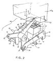
- Fig. 2 is a perspective view of the positioning mechanism and of the capping system for sealing of the area of the printhead bearing the nozzles, according to a first, preferred embodiment.
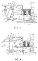
- Fig. 3 is a side elevational view of the positioning mechanism and of the capping system for sealing of the area of the printhead bearing the nozzles, according to a first, preferred embodiment, in the event that the storage apparatus contains a printhead for colour printing.
- Fig. 4 is a side elevational view of the positioning mechanism and of the capping system for sealing of the area of the printhead bearing the nozzles, according to a first, preferred embodiment, in the event that the storage apparatus contains a printhead for black printing.
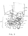
- Fig. 5 is a perspective view of the positioning mechanism and of the capping system for sealing of the area of the printhead bearing the nozzles, according to a second, preferred embodiment.
- Fig. 6 is a side elevational view of the positioning mechanism and of the capping system for sealing of the area of the printhead bearing the nozzles, according to a second, preferred embodiment, in the event that the storage apparatus contains a printhead for colour printing.
- Fig. 7 is a side elevational view of the positioning mechanism and of the capping system for sealing of the area of the printhead bearing the nozzles, according to a second, preferred embodiment, in the event that the storage apparatus contains a printhead for black printing.
- the storage apparatus comprises a container 10 (Fig. 1) of substantially parallepiped shape, consisting of a base 11, in one top surface 13 of which an aperture 14 has been made, the perimeter 9 of which, duly shaped, serves as a guide and provides the orientation for insertion of a printhead 50a (illustrated in overlay), and having a lid 12.
- the parallepiped shape is obviously not limiting, as the container 10 could also for example be cylindrical in shape.
- the printhead 50a is inserted in the container 10 with identical orientation for both types, and in exactly the same way as for its insertion in the printhead carriage of a printer, thereby avoiding all problems for the user.
- a snap-fit catch (not shown in the figure), similar to the one on the printhead carriage of the printer and known in the art, is used to stably lock the printhead 50a inside the container 10, simultaneously providing the user both tactile and audible confirmation that the printhead has been correctly inserted in the storage apparatus.
- a capping system 5 (Fig. 2) that will be described in greater detail in the following, comprising a synthetic rubber cap 15 which is selectively brought into contact by a position mechanism 30 with a support face 52 of the printhead 50a bearing the ejector plate containing the nozzles 51 for discharge of the ink, thereby isolating the latter from the external atmosphere.
- Rubber cap 15 comprises an outside wall 16 which terminates, confronting the support face 52 of printhead 50a at its top portion, in an external elastic rim 17, and an inside wall 19 which terminates, also confronting support face 52 at its top portion, in an internal elastic rim 18.
- Both the outside 16 and inside 19 walls are approximately rectangular in shape and are arranged concentrically around a hollow central area 40, bottom portion of which is connected to a flexible pipe 42.
- the two elastic rims, internal 18 and external 17, define an area which, when projected on to support face 52, surrounds the nozzles 51, respectively of the printhead for black printing 50b and of the printhead for colour printing 50c.
- Cap 15 is fitted on a support 20 comprising two concentric members, external member 21 and internal member 22 (Fig. 3), in such a way that the outside wall 16 is in contact with and bound to external member 21 and the inside wall 19 is in contact with and bound to internal member 22; the coupling between wall 16, 19 and member 21, 22 may be made, as in Fig. 3, by fittings formed of protrusions 43a and corresponding recesses 43b, made by modifying respectively the thicknesses of walls 16, 19 and of sliding members 21, 22, or using other systems, for example gluing, vulcanization, rivetting, etc.
- the internal 22 and external 21 translating members are capable of translating or reciprocating over a distance of length "d", before assuming two defined positions, shown respectively in Figs. 3 and 4: the position of Fig. 3 is that assumed when a printhead 50c for colour printing is inserted in container 10, whereas the position in Fig. 4 is that assumed when a printhead 50c for black printing is inserted in the storage apparatus, or when no printhead is inserted therein.
- support 20 assumes the position of Fig. 4 due to the action of a return spring 23 (shown schematically in the figure as an arrow), which brings a probe arm 24 against a suitably disposed stop 44; when there is a printhead 50b, 50c inside container 10, the base 20 assumes, in this case, one or other of the two positions shown in Figs. 3 and 4, depending on the command transmitted to it by positioning mechanism 30.
- a return spring 23 shown schematically in the figure as an arrow
- Positioning mechanism 30 (Fig. 2) comprises a lever with a plurality of arms 45, consisting of a central pipe 25 acting as a rotatable fulcrum with respect to an axis 26, whereto are attached the probe arm 24, a spring-holder arm 31, substantially aligned with probe arm 24, a first lever 27 and a second lever 28, generically at right angles with respect to probe arm 24 and parallel to each other.
- Probe arm 24 possesses one end 29, apt to come into contact with printhead 50a when inserted in container 10.
- the spring-holder arm 31, at the end opposite that by which it is fixed to pipe 25, is equipped with an eyelet 32, whereto return spring 23 is attached (not shown in the figure).
- the two levers 27, 28 each bear, at the end opposite that by which they are fixed to pipe 25, respectively a first pin 33 and a second pin 34.
- Positioning mechanism 30 also comprises a balancer arm member 35, comprising a pair of arms 36, substantially parallel to each other and connected by a cross-piece 38 substantially perpendicular to both, and a shaft 39 around which it is free to rotate.
- Arms 36 are equipped with two forked ends 41 apt to engage with pins 33, 34, and are connected to each other in a central position by a shaft 37, substantially parallel to the axis of rotation 39 and to the cross-piece 38, which is rotatably coupled to internal sliding member 22 of support 20, whereto cap 15 is fitted.
- Positioning mechanism 30 as a whole represents a system of linkages which transmits to cap 15 the motion of the end 29 of probe 24, when printhead 50a is inserted in container 10.
- a flexible hose 42 is connected at one end to the hollow central area 40 of cap 15 and at the other to a serpentine passageway, not shown in the figure, achieved by means of a capillary tube in a bottom wall 8 of container 10, which in turn is in connection with the outside world, the purpose of this being to constitute a considerable obstacle to diffusion to the outside world of the atmosphere enclosed between the support face 52 of printhead 50b and internal rim 18 of cap 15, (or, correspondingly, between the support face 52 of printhead 50c and external rim 17), though permitting instantaneous adaptation of said atmosphere to variations in pressure of the outside world.
- the two printheads 50b e 50c differ, as in many other characteristics not relevant to the scope of this invention, in the fact that dimensions of the support face 52 bearing the ejector plate containing the nozzles 51 are greater for the colour printing printhead than for the black printing printhead.
- the starting configuration of positioning mechanism 30 is that shown in Fig. 4, where probe arm 24 is at rest against stop 44 through the action of return spring 23, as there is no printhead inside container 10; when the printhead 50c for colour printing Is inserted in container 10 (Fig. 3), end 29 of probe arm 24 will come into contact with support face 52 of printhead 50c, and probe arm 24 will be made rotate clockwise in the downward direction to contrast action of return spring 23.
- internal rim 18 first finds itself under external rim 17, and subsequently external rim 17 is brought first to rest against and then pressed lightly against support face 52, so that an efficacious seal is achieved.
- printhead 50b for black printing has to be removed from the printhead carriage of the ink jet printer with interchangeable printheads
- printhead 50c for colour printing removed from the storage apparatus and inserted in the printhead carriage
- printhead 50b for black printing has to be inserted in container 10.
- a positioning mechanism 60 (Fig. 5) and a capping system 55 which, by means of a rotary motion imparted to it by positioning mechanism 60, selectively couples to support face 52 bearing the ejector plate containing the nozzles 51 of printhead 50a, to seal the nozzles 51 from the surrounding atmosphere.
- Positioning mechanism 60 comprises a first lever 75 consisting of a central hose 63 acting as a rotatable fulcrum around a shaft 64, a crankarm 62, a spring-holder arm 65 substantially at right angles to the crankarm 62, and an arm 67 disposed in an intermediate position between crankarm 62 and spring-holder arm 65.
- Crankarm 62 is equipped with a probe pin 61 fixedly attached at the end opposite that at which arm 62 is attached to the hose 63; the spring-holder arm 65 has an eyelet 66, at the end opposite that by which it is attached to hose 63, to which a return spring 68, not shown in the figure, is hooked. Finally arm 67 terminates, at the end opposite that by which it is attached to hose 63, in a support member 70.
- Positioning mechanism 60 also comprises a second lever 76, consisting of a central hose 83 with the function of a rotatable fulcrum with respect to a shaft 78, an arm 79, and a V-shape support base, located substantially diametrically opposite arm 79 with respect to hose 83.
- Arm 79 is equipped in an intermediate position with a support end 73 which is kept in contact with support element 70 of lever 75 through the action of a tension spring 69, shown schematically in the figure as an arrow, hooked respectively to arm 79 and arm 67.
- Arm 79 terminates, at the end opposite that by which it is attached to hose 83, in a stop blade 74, movable between a first fixed stop 71 and a second fixed stop 72.
- the capping system 55 comprises a rubber cap 80, fitted on the two legs of the V-shape support base 77, which in turn comprises two, separate elastic rims, both approximately rectangular in shape but of different dimensions: a first rim 81 designed to seal printhead 50b for black printing (Fig. 7), and a second rim 82, designed to seal printhead 50c for colour printing (Fig. 6).
- the support base 77 by way of rotation around shaft 78, may adopt two defined positions, shown respectively in Figs. 6 and 7: the position of Fig. 6 is that adopted when printhead 50c for colour printing is inserted in container 10, while the position of Fig. 7 is that adopted when printhead 50b for black printing is inserted in container 10, or when there is no printhead therein.
- support base 77 When there is no printhead inside container 10, support base 77 adopts the position Fig. 7 through the action of return spring 68; on the other hand, when there is a printhead inside container 10, the support base 77 adopts one or other of the two positions shown in Figs. 6 and 7, depending on the command transmitted to it by positioning mechanism 60, when probe pin 61 comes into contact with printhead 50a while the latter is being inserted in container 10 and levers 75, 76 command rotating motion of support base 77 around shaft 78.
- Cap 80 on the side opposite elastic rims 81, 82, is equipped with a tube (not shown) which is attached to a flexible tube 84 (Fig. 5), with characteristics and functions identical to those described with reference to the first preferred embodiment of the storage apparatus in accordance with the present invention, which should be consulted for details.
- Support base 77 also rotating in the counter-clockwise direction, brings second elastic rim 82 into contact with support face 52 bearing nozzles 51, so that an efficacious seal is achieved. Further, as the volume of air between cap 80 and printhead 50c is in communication with the outside through flexible tube 84, during the compression of external rim 82, no excess of pressure is created, which could push the ink away from the nozzles 51; similarly, in subsequent removal of printhead 50c from container 10, no depression is created, which could suck ink back from nozzles 51.
- printhead 50b for black printing has to be removed from the printhead carriage of the ink jet printer with interchangeable printheads
- printhead 50c for colour printing removed from the storage apparatus and inserted in the printhead carriage
- printhead 50b for black printing has to be inserted in container 10.
- return spring 68 causes first lever 75 to rotate clockwise around shaft 64, so that support member 70 in its travel meets with support end 73 of second lever 77 and produces counter-clockwise rotation of arm 79, so that stop blade 74 first detaches itself from contact with first fixed stop 71 and then, continuing its rotation about 78, finally stops against second fixed stop 72.
- Support base 77 also rotating in the clockwise direction, brings first elastic rim 81 into the vertical position (Fig. 7).
- first elastic rim 81 comes first into contact with support face 52 bearing nozzles 51 and then, with printhead 50b continuing its travel, is pressed lightly against support face 52, so that an efficacious seal is achieved.
- Both the first and the second version of the preferred embodiment of the storage apparatus in the above description have the advantage of requiring an amount of space only slightly superior to the volume occupied by the printhead and are thus suitable for inclusion inside the printer casing, thereby excluding the need for a dedicated container which, though small as it may be, still represents an extra cost and an irritating encumbrance for the printer user.
Landscapes
- Ink Jet (AREA)
Applications Claiming Priority (2)
| Application Number | Priority Date | Filing Date | Title |
|---|---|---|---|
| IT94TO001056A IT1267355B1 (it) | 1994-12-22 | 1994-12-22 | Dispositivo di ricovero per testina di stampa a getto di inchiostro. |
| ITTO941056 | 1994-12-22 |
Publications (3)
| Publication Number | Publication Date |
|---|---|
| EP0726153A2 EP0726153A2 (en) | 1996-08-14 |
| EP0726153A3 EP0726153A3 (OSRAM) | 1996-08-21 |
| EP0726153B1 true EP0726153B1 (en) | 2000-03-15 |
Family
ID=11412995
Family Applications (1)
| Application Number | Title | Priority Date | Filing Date |
|---|---|---|---|
| EP95119760A Expired - Lifetime EP0726153B1 (en) | 1994-12-22 | 1995-12-14 | Ink-jet print head storage apparatus |
Country Status (4)
| Country | Link |
|---|---|
| US (1) | US5867187A (OSRAM) |
| EP (1) | EP0726153B1 (OSRAM) |
| DE (1) | DE69515631T2 (OSRAM) |
| IT (1) | IT1267355B1 (OSRAM) |
Families Citing this family (14)
| Publication number | Priority date | Publication date | Assignee | Title |
|---|---|---|---|---|
| DE69732403T2 (de) * | 1996-11-22 | 2006-03-30 | Canon K.K. | Ein Tintenstrahlaufzeichnungsgerät |
| JP3483410B2 (ja) | 1996-11-26 | 2004-01-06 | キヤノン株式会社 | インクジェット記録装置 |
| US6273546B1 (en) * | 1996-11-29 | 2001-08-14 | Seiko Epson Corporation | Capping unit having a decreased load during a peeling operation and ink-jet recording apparatus using the same |
| DE69835249T2 (de) | 1997-02-18 | 2007-07-05 | Canon K.K. | Flüssigkeitsausstossvorrichtung |
| US6309891B1 (en) * | 1998-09-09 | 2001-10-30 | Incyte Genomics, Inc. | Capillary printing systems |
| US6350010B1 (en) | 1999-08-16 | 2002-02-26 | Lexmark International, Inc. | Printer having one or more print cartridges installed during manufacture |
| US6443553B2 (en) | 1999-08-16 | 2002-09-03 | Lexmark International, Inc | Printer having one or more print cartridges installed during manufacture |
| US6733106B1 (en) * | 2002-10-24 | 2004-05-11 | Lexmark International, Inc. | Ink jet maintenance station with radial orientation |
| US6843550B2 (en) * | 2003-04-22 | 2005-01-18 | Hewlett-Packard Development Company, L.P. | Printhead servicing mechanism and method |
| US6817695B1 (en) | 2003-06-03 | 2004-11-16 | Lexmark International, Inc. | Printhead capping assembly |
| US7021741B2 (en) * | 2003-11-21 | 2006-04-04 | Lexmark International, Inc. | Printhead cap assembly for an ink jet printer |
| US7258434B2 (en) * | 2003-11-24 | 2007-08-21 | Lexmark International, Inc. | Inkjet printheads having multiple label placement positions for air diffusion vents |
| JP4626264B2 (ja) | 2004-10-28 | 2011-02-02 | ブラザー工業株式会社 | 記録ヘッドの保管装置および保管方法 |
| JP5316506B2 (ja) | 2010-09-30 | 2013-10-16 | ブラザー工業株式会社 | 液体吐出装置 |
Family Cites Families (4)
| Publication number | Priority date | Publication date | Assignee | Title |
|---|---|---|---|---|
| JPS61230946A (ja) * | 1985-04-08 | 1986-10-15 | Tokyo Electric Co Ltd | 印刷装置 |
| US5155497A (en) | 1991-07-30 | 1992-10-13 | Hewlett-Packard Company | Service station for ink-jet printer |
| JP2925394B2 (ja) * | 1992-03-09 | 1999-07-28 | キヤノン株式会社 | 保管容器 |
| US5585826A (en) * | 1993-04-30 | 1996-12-17 | Hewlett-Packard Company | Service station for simultaneous capping/wiping of multiple inkjet cartridges having different inks |
-
1994
- 1994-12-22 IT IT94TO001056A patent/IT1267355B1/it active IP Right Grant
-
1995
- 1995-12-14 EP EP95119760A patent/EP0726153B1/en not_active Expired - Lifetime
- 1995-12-14 DE DE69515631T patent/DE69515631T2/de not_active Expired - Lifetime
- 1995-12-18 US US08/574,316 patent/US5867187A/en not_active Expired - Lifetime
Non-Patent Citations (1)
| Title |
|---|
| DeskJet 500 C Aufbauanleitung, ArtNr.C2114-90013, Hewlett Packard Co. 09.1992 * |
Also Published As
| Publication number | Publication date |
|---|---|
| US5867187A (en) | 1999-02-02 |
| IT1267355B1 (it) | 1997-01-28 |
| EP0726153A3 (OSRAM) | 1996-08-21 |
| EP0726153A2 (en) | 1996-08-14 |
| DE69515631D1 (de) | 2000-04-20 |
| ITTO941056A1 (it) | 1996-06-22 |
| ITTO941056A0 (it) | 1994-12-22 |
| DE69515631T2 (de) | 2000-08-31 |
Similar Documents
| Publication | Publication Date | Title |
|---|---|---|
| EP0726153B1 (en) | Ink-jet print head storage apparatus | |
| US4737801A (en) | Ink supply device and an ink jet recording apparatus having the ink supply device | |
| EP0597675B1 (en) | Valve for an ink jet printer maintenance system | |
| EP2783862B1 (en) | Liquid cartridge | |
| EP0778147B1 (en) | Apparatus and method for filling ink cartridges | |
| JP3082963B2 (ja) | 大気連通部を備えたインク収納容器及び記録ヘッド | |
| US20030076391A1 (en) | Supply adaptor for an on-axis printer | |
| US9205658B2 (en) | Ink cartridge and method of producing the same | |
| US20040174417A1 (en) | Ink-jet recording apparatus | |
| JPH09164698A (ja) | インクジェット・プリンタ用インク供給部 | |
| EP2512809B1 (en) | Protection device for ink-jet printhead | |
| EP0576033A2 (en) | Ink-jet recording device | |
| EP0783434A1 (en) | Refill assembly and system for ink-jet printer cartridges | |
| US6360795B1 (en) | Device and arrangement for filling an ink reservoir | |
| EP1007364B1 (en) | Ink container configured for use with a printing device having an out-of-ink sensing system | |
| JP2003200586A5 (OSRAM) | ||
| JP3669240B2 (ja) | インクジェット式記録装置 | |
| JP2001072153A (ja) | 液体吐出装置および液体吐出量調整装置 | |
| JP3603637B2 (ja) | インクジェット式記録装置 | |
| JPH0521745B2 (OSRAM) | ||
| EP4289627A1 (en) | Fluid ejection device and handheld fluid ejection device | |
| JP2011016236A (ja) | インク充填用治具、インク充填装置、インク充填方法、インク充填キット | |
| KR100306422B1 (ko) | 인쇄장치의잉크헤드용청소장치 | |
| JPH0380110B2 (OSRAM) | ||
| JPH0230290Y2 (OSRAM) |
Legal Events
| Date | Code | Title | Description |
|---|---|---|---|
| PUAI | Public reference made under article 153(3) epc to a published international application that has entered the european phase |
Free format text: ORIGINAL CODE: 0009012 |
|
| PUAL | Search report despatched |
Free format text: ORIGINAL CODE: 0009013 |
|
| AK | Designated contracting states |
Kind code of ref document: A2 Designated state(s): DE FR GB |
|
| AK | Designated contracting states |
Kind code of ref document: A3 Designated state(s): DE FR GB |
|
| 17P | Request for examination filed |
Effective date: 19970425 |
|
| 17Q | First examination report despatched |
Effective date: 19980604 |
|
| RAP1 | Party data changed (applicant data changed or rights of an application transferred) |
Owner name: OLIVETTI LEXIKON S.P.A. |
|
| GRAG | Despatch of communication of intention to grant |
Free format text: ORIGINAL CODE: EPIDOS AGRA |
|
| GRAG | Despatch of communication of intention to grant |
Free format text: ORIGINAL CODE: EPIDOS AGRA |
|
| GRAH | Despatch of communication of intention to grant a patent |
Free format text: ORIGINAL CODE: EPIDOS IGRA |
|
| GRAH | Despatch of communication of intention to grant a patent |
Free format text: ORIGINAL CODE: EPIDOS IGRA |
|
| GRAA | (expected) grant |
Free format text: ORIGINAL CODE: 0009210 |
|
| AK | Designated contracting states |
Kind code of ref document: B1 Designated state(s): DE FR GB |
|
| REF | Corresponds to: |
Ref document number: 69515631 Country of ref document: DE Date of ref document: 20000420 |
|
| ET | Fr: translation filed | ||
| PLBE | No opposition filed within time limit |
Free format text: ORIGINAL CODE: 0009261 |
|
| STAA | Information on the status of an ep patent application or granted ep patent |
Free format text: STATUS: NO OPPOSITION FILED WITHIN TIME LIMIT |
|
| 26N | No opposition filed | ||
| REG | Reference to a national code |
Ref country code: GB Ref legal event code: IF02 |
|
| PGFP | Annual fee paid to national office [announced via postgrant information from national office to epo] |
Ref country code: DE Payment date: 20141121 Year of fee payment: 20 Ref country code: GB Payment date: 20141126 Year of fee payment: 20 |
|
| PGFP | Annual fee paid to national office [announced via postgrant information from national office to epo] |
Ref country code: FR Payment date: 20141217 Year of fee payment: 20 |
|
| REG | Reference to a national code |
Ref country code: DE Ref legal event code: R082 Ref document number: 69515631 Country of ref document: DE Representative=s name: WEICKMANN & WEICKMANN PATENTANWAELTE - RECHTSA, DE Ref country code: DE Ref legal event code: R082 Ref document number: 69515631 Country of ref document: DE Representative=s name: PATENTANWAELTE WEICKMANN & WEICKMANN, DE |
|
| REG | Reference to a national code |
Ref country code: DE Ref legal event code: R071 Ref document number: 69515631 Country of ref document: DE |
|
| REG | Reference to a national code |
Ref country code: GB Ref legal event code: PE20 Expiry date: 20151213 |
|
| PG25 | Lapsed in a contracting state [announced via postgrant information from national office to epo] |
Ref country code: GB Free format text: LAPSE BECAUSE OF EXPIRATION OF PROTECTION Effective date: 20151213 |