EP0726119B1 - Mehrspindelwerkzeugmaschine - Google Patents
Mehrspindelwerkzeugmaschine Download PDFInfo
- Publication number
- EP0726119B1 EP0726119B1 EP96101881A EP96101881A EP0726119B1 EP 0726119 B1 EP0726119 B1 EP 0726119B1 EP 96101881 A EP96101881 A EP 96101881A EP 96101881 A EP96101881 A EP 96101881A EP 0726119 B1 EP0726119 B1 EP 0726119B1
- Authority
- EP
- European Patent Office
- Prior art keywords
- spindle
- support
- work piece
- machine tool
- tool according
- Prior art date
- Legal status (The legal status is an assumption and is not a legal conclusion. Google has not performed a legal analysis and makes no representation as to the accuracy of the status listed.)
- Expired - Lifetime
Links
- 238000003754 machining Methods 0.000 claims description 16
- 230000000063 preceeding effect Effects 0.000 claims 1
- 210000003128 head Anatomy 0.000 description 15
- 238000012545 processing Methods 0.000 description 13
- 238000004519 manufacturing process Methods 0.000 description 6
- 239000000969 carrier Substances 0.000 description 2
- 238000005520 cutting process Methods 0.000 description 2
- 238000005553 drilling Methods 0.000 description 2
- 230000005484 gravity Effects 0.000 description 2
- 238000003780 insertion Methods 0.000 description 2
- 230000037431 insertion Effects 0.000 description 2
- 239000000463 material Substances 0.000 description 2
- 238000003860 storage Methods 0.000 description 2
- 238000013459 approach Methods 0.000 description 1
- 230000005540 biological transmission Effects 0.000 description 1
- 230000015572 biosynthetic process Effects 0.000 description 1
- 239000012459 cleaning agent Substances 0.000 description 1
- 230000001427 coherent effect Effects 0.000 description 1
- 238000010276 construction Methods 0.000 description 1
- 239000002826 coolant Substances 0.000 description 1
- 238000013461 design Methods 0.000 description 1
- 238000009826 distribution Methods 0.000 description 1
- 230000002349 favourable effect Effects 0.000 description 1
- 238000000034 method Methods 0.000 description 1
- 230000000149 penetrating effect Effects 0.000 description 1
- 230000000630 rising effect Effects 0.000 description 1
- 238000012549 training Methods 0.000 description 1
Images


Classifications
-
- B—PERFORMING OPERATIONS; TRANSPORTING
- B23—MACHINE TOOLS; METAL-WORKING NOT OTHERWISE PROVIDED FOR
- B23Q—DETAILS, COMPONENTS, OR ACCESSORIES FOR MACHINE TOOLS, e.g. ARRANGEMENTS FOR COPYING OR CONTROLLING; MACHINE TOOLS IN GENERAL CHARACTERISED BY THE CONSTRUCTION OF PARTICULAR DETAILS OR COMPONENTS; COMBINATIONS OR ASSOCIATIONS OF METAL-WORKING MACHINES, NOT DIRECTED TO A PARTICULAR RESULT
- B23Q11/00—Accessories fitted to machine tools for keeping tools or parts of the machine in good working condition or for cooling work; Safety devices specially combined with or arranged in, or specially adapted for use in connection with, machine tools
- B23Q11/08—Protective coverings for parts of machine tools; Splash guards
-
- B—PERFORMING OPERATIONS; TRANSPORTING
- B23—MACHINE TOOLS; METAL-WORKING NOT OTHERWISE PROVIDED FOR
- B23Q—DETAILS, COMPONENTS, OR ACCESSORIES FOR MACHINE TOOLS, e.g. ARRANGEMENTS FOR COPYING OR CONTROLLING; MACHINE TOOLS IN GENERAL CHARACTERISED BY THE CONSTRUCTION OF PARTICULAR DETAILS OR COMPONENTS; COMBINATIONS OR ASSOCIATIONS OF METAL-WORKING MACHINES, NOT DIRECTED TO A PARTICULAR RESULT
- B23Q1/00—Members which are comprised in the general build-up of a form of machine, particularly relatively large fixed members
- B23Q1/0009—Energy-transferring means or control lines for movable machine parts; Control panels or boxes; Control parts
-
- B—PERFORMING OPERATIONS; TRANSPORTING
- B23—MACHINE TOOLS; METAL-WORKING NOT OTHERWISE PROVIDED FOR
- B23Q—DETAILS, COMPONENTS, OR ACCESSORIES FOR MACHINE TOOLS, e.g. ARRANGEMENTS FOR COPYING OR CONTROLLING; MACHINE TOOLS IN GENERAL CHARACTERISED BY THE CONSTRUCTION OF PARTICULAR DETAILS OR COMPONENTS; COMBINATIONS OR ASSOCIATIONS OF METAL-WORKING MACHINES, NOT DIRECTED TO A PARTICULAR RESULT
- B23Q1/00—Members which are comprised in the general build-up of a form of machine, particularly relatively large fixed members
- B23Q1/01—Frames, beds, pillars or like members; Arrangement of ways
- B23Q1/015—Frames, beds, pillars
-
- B—PERFORMING OPERATIONS; TRANSPORTING
- B23—MACHINE TOOLS; METAL-WORKING NOT OTHERWISE PROVIDED FOR
- B23Q—DETAILS, COMPONENTS, OR ACCESSORIES FOR MACHINE TOOLS, e.g. ARRANGEMENTS FOR COPYING OR CONTROLLING; MACHINE TOOLS IN GENERAL CHARACTERISED BY THE CONSTRUCTION OF PARTICULAR DETAILS OR COMPONENTS; COMBINATIONS OR ASSOCIATIONS OF METAL-WORKING MACHINES, NOT DIRECTED TO A PARTICULAR RESULT
- B23Q39/00—Metal-working machines incorporating a plurality of sub-assemblies, each capable of performing a metal-working operation
- B23Q39/04—Metal-working machines incorporating a plurality of sub-assemblies, each capable of performing a metal-working operation the sub-assemblies being arranged to operate simultaneously at different stations, e.g. with an annular work-table moved in steps
- B23Q39/042—Metal-working machines incorporating a plurality of sub-assemblies, each capable of performing a metal-working operation the sub-assemblies being arranged to operate simultaneously at different stations, e.g. with an annular work-table moved in steps with circular arrangement of the sub-assemblies
- B23Q39/046—Metal-working machines incorporating a plurality of sub-assemblies, each capable of performing a metal-working operation the sub-assemblies being arranged to operate simultaneously at different stations, e.g. with an annular work-table moved in steps with circular arrangement of the sub-assemblies including a loading and/or unloading station
-
- Y—GENERAL TAGGING OF NEW TECHNOLOGICAL DEVELOPMENTS; GENERAL TAGGING OF CROSS-SECTIONAL TECHNOLOGIES SPANNING OVER SEVERAL SECTIONS OF THE IPC; TECHNICAL SUBJECTS COVERED BY FORMER USPC CROSS-REFERENCE ART COLLECTIONS [XRACs] AND DIGESTS
- Y10—TECHNICAL SUBJECTS COVERED BY FORMER USPC
- Y10T—TECHNICAL SUBJECTS COVERED BY FORMER US CLASSIFICATION
- Y10T82/00—Turning
- Y10T82/25—Lathe
- Y10T82/2524—Multiple
-
- Y—GENERAL TAGGING OF NEW TECHNOLOGICAL DEVELOPMENTS; GENERAL TAGGING OF CROSS-SECTIONAL TECHNOLOGIES SPANNING OVER SEVERAL SECTIONS OF THE IPC; TECHNICAL SUBJECTS COVERED BY FORMER USPC CROSS-REFERENCE ART COLLECTIONS [XRACs] AND DIGESTS
- Y10—TECHNICAL SUBJECTS COVERED BY FORMER USPC
- Y10T—TECHNICAL SUBJECTS COVERED BY FORMER US CLASSIFICATION
- Y10T82/00—Turning
- Y10T82/25—Lathe
- Y10T82/2531—Carriage feed
- Y10T82/2549—Feedscrews and rods
-
- Y—GENERAL TAGGING OF NEW TECHNOLOGICAL DEVELOPMENTS; GENERAL TAGGING OF CROSS-SECTIONAL TECHNOLOGIES SPANNING OVER SEVERAL SECTIONS OF THE IPC; TECHNICAL SUBJECTS COVERED BY FORMER USPC CROSS-REFERENCE ART COLLECTIONS [XRACs] AND DIGESTS
- Y10—TECHNICAL SUBJECTS COVERED BY FORMER USPC
- Y10T—TECHNICAL SUBJECTS COVERED BY FORMER US CLASSIFICATION
- Y10T82/00—Turning
- Y10T82/25—Lathe
- Y10T82/2552—Headstock
- Y10T82/2562—Spindle and bearings
Definitions
- the invention relates to a multi-spindle machine tool comprising a machine frame rising above a base area, one on the machine frame around a base penetrating and extending from this axis of rotation rotatably mounted spindle carrier, several on the spindle carrier around the axis of rotation one at a time
- Spindle positions of hanging workpiece spindles, whose spindle axes penetrate the base and move away from this extend away and that by turning the spindle carrier Can be positioned around the axis of rotation in various rotary positions are a work space in which the workpiece spindles protrude with their workpiece clamping devices, and an in the tool arranged tool with which a in the Workpiece clamping device one of the workpiece spindles clamped Workpiece is editable.
- the machine frame includes a lower part standing on the base.
- Such a machine tool according to the preamble of the only independent Claim 1 is from US 3,792,633 known, with this the workpiece spindles on one a central column rotatably and this enclosing stand are arranged, which also the Carries tools.
- Such a machine tool is also, for example from the article "Conception more appropriate to use Lathes that change the image of automation Machine Tool "by Prof. Eversheim and Dipl. Ing. Päffekhofen, published in the magazine "Industriean Attacher” No. 19 of March 19, 1983, known.
- This article shows the arrangement of two hanging in picture 4 Spindles described on a spindle drum, which in turn rotatable in relation to an inverted U-shaped machine frame is mounted, being on a side support of the machine frame a tool slide that can be moved in two axial directions is provided.
- a lathe with one that can be moved along its spindle axis single hanging spindle is also out of the DE-C 34 16 660 known or also from EP-B 0 215 209.
- Die single-spindle machines disclosed in the latter two publications have a numerically controlled in the Z-axis direction sliding spindle that serves both To grasp workpieces as well as the workpieces relatively to guide a fixed tool during processing.
- the invention is therefore based on the object of a multi-spindle machine tool of the generic type improve that they are as compact and stable is.
- the task mentioned at the beginning is also at a initially mentioned multi-spindle machine tool according to the invention solved in that starting from the lower part radially to and through the axis of rotation support elements lying in the planes that rise extend to a support ring and wear this that the Supporting ring supports the spindle carrier that the workpiece spindles arranged in their spindle positions around the axis of rotation are and that radially within the support members about the axis of rotation around a work space for editing the in the Workpieces held workpieces is arranged.
- the support elements are flat in the planes extending bodies formed so that their extension is as low as possible in the azimuthal direction.
- the support elements are based on an orbit Workpiece spindles extend radially outwards so that inside the support elements an azimuthal around the axis of rotation running working space is given, in which the Can move workpiece spindles unhindered.
- a particularly useful embodiment provides that the supporting elements are designed as supporting walls.
- the work space one of the number of Workpiece spindles has a corresponding number of stations, in which the workpiece spindles can be positioned and that the support elements each between two successive Stations are arranged.
- the support elements could be arranged as desired can as long as they are between successive stations stand. It is particularly expedient here if the supporting elements arranged at equal angular distances from each other are to ensure that the behavior of the Machine frame, especially the support elements together with the Tragring, with changing temperature and occurring To achieve burdens.
- a particularly advantageous solution provides that between two consecutive stations one the support elements is arranged so that ultimately the number the number of support elements provided for the workpiece spindles Stations.
- the lower part a radially extending to the support elements and running around the axis of rotation and on the base supporting outer body includes.
- the support elements are connected to the outer body, preferably one Detachable connection between the support elements and the outer body consists.
- an advantageous embodiment provides that the spindle carrier is rotatably supported by a bearing, which is located radially outside of the workpiece spindles orbits described when the spindle carrier is rotated.
- the support ring supports the bearing for the spindle carrier.
- the rotary drive for the spindle carrier could be arranged separately. However, it is particularly advantageous if the rotary drive for the spindle carrier is also on Support ring is arranged.
- the rotary drive could be on any side of the Support ring may be arranged. To make it as accessible as possible However, it is particularly advantageous to maintain a work space if the rotary drive is arranged on the support ring is and over the support ring in the direction of the axis of rotation extends.
- the spindle carrier could be supported in many ways respectively. It when the support ring is particularly advantageous engages the spindle carrier on an outside thereof as stable a support of the spindle carrier as possible guarantee.
- a workpiece spindle in the sense of the present invention is to be understood in particular a device which a rotatable about the spindle axis by means of a drive Workpiece holding means, wherein the workpiece holding means for example with the drive for a classic Machining usual speeds and torques driven is defined by the drive or only in Positions can be positioned, in which case the Drive preferably as a numerically controlled C axis is trained, or by the drive both as a classic Rotary spindle as well as a numerically controlled C axis is operable.
- the tool can also be attached to the spindle carrier to arrange and thus the tool together with the workpiece spindles mitzube admire.
- the lower part has a Tool carrier for the tool carries, because it is easy accessible mounting of the tool holder and a special dimensionally stable fixation of the same on the lower part is possible.
- a particularly expedient solution provides that the Tool carrier is arranged on the outer body of the lower part and thus an assembly of the tool holder from outside the Machine frame possible in an ergonomically favorable way is.
- the machine tool according to the invention in the spindle station provided with the tool to work with a fixed tool.
- the tool carrier movable radially to the spindle axis of the respective workpiece spindle is to by appropriate movement of the tool carrier with the tool different positions of the tool to be able to implement relative to the workpiece.
- a particularly useful solution in particular the Allows conventional turning operations to be carried out, provides that the tool is controlled by an NC-controlled X axis radial to the spindle axis in the respective spindle station stationary workpiece spindle is movable and positionable. This gives you the option, for example, of rigid workpiece spindles connected to the spindle carrier all simple possible turning operations with an X axis.
- the tool carrier sits on a slide that can be moved in the X-axis, whereby this carriage in the usual way in machine tools is movable along the X axis, for example with a Spindle drive.
- a sled guide which on Lower part, preferably the outer body of the same, mounted is.
- the workpiece spindles can run along their Spindle axis arranged immovable relative to the machine frame his.
- the tool carrier available with the tool through a slide system in the Z direction to move relative to the workpiece spindle.
- the workpiece spindles relative to the spindle carrier in the direction of its spindle axis are movable independently of one another, so that the Movements in the direction of the spindle axis for each one Workpiece spindle according to the task to be carried out can be done.
- each workpiece spindle has its own linear drive for movement the same is assigned in the direction of the spindle axis.
- the workpiece spindles can be positioned in different spindle stations are possible, stationary on the machine frame everyone Assign a linear drive to the spindle station and the workpiece spindles to be coupled to each spindle station and before switching the spindle carrier from disconnect it again.
- each Workpiece spindle in the direction of the spindle axis using the Linear actuator is defined positionable and fixable, so that no additional devices are required to the workpiece spindle after positioning in it Position still to be fixed.
- Such a multi-spindle machine tool can be particularly advantageous then train when the linear drive is on the spindle carrier sits and preferably also on Spindle carrier seated drive motor includes.
- the linear drive on the spindle carrier related to the respective workpiece spindle is arranged radially outside.
- Particularly space-saving is an arrangement in which the linear drive in an angular range between two successive workpiece spindles is arranged, in particular provided is that the linear actuator is related to two consecutive Workpiece spindles on gap, that is essentially is arranged centrally between these.
- the workpiece spindles are, for example, when large Drive powers are required with a separate Spindle drive, for example one behind this flanged drive motor.
- each workpiece spindle as Motor spindle is formed, because in this case the spindle drive preferably integrated in a quill of this spindle can be arranged.
- the work area has a movement space for the workpiece spindles includes, which is self-contained and continuous runs around the central axis.
- Such one Working space enables easy switching of the workpiece spindles in the individual spindle stations.
- the Workspace associated with at least one spindle station Chip generation room includes, in this chip production room the tool moves and this preferably so is formed that the chips generated in this Following gravity fall down and transported away can be.
- an advantageous solution provides that the Workspace associated with at least one spindle station Includes loading or unloading space in which a workpiece for insertion into the workpiece spindle in this spindle station is made available or a workpiece from a work spindle in this spindle station picked up and transported away by a transport device becomes.
- an advantageous embodiment provides that the work area is unhindered from the outside is accessible through elements running towards the lower part, so that any disability caused thereby There is no access to the work area.
- the lower part includes a chip tray located below the work area.
- the lower part is preferably designed such that this is a chip tray running underneath the work area has, so that each of the spindle stations with the chip pan is connected and especially from the individual, the spindle stations assigned rooms each chips or cutting material or Cleaning agents can be removed.
- the workpiece spindles with their spindle axes at constant angular intervals around the Axis of rotation are arranged to create the possibility when the spindle carrier rotates, each of the workpiece spindles in to bring the nearest spindle station.
- All spindle axes are preferably essentially arranged parallel to the axis of rotation of the spindle carrier and have the same angle in particular, with the spindle axes from the parallel alignment to the axis of rotation a maximum of a few degrees, preferably less than 5 degrees differ.
- the axis of rotation of the spindle carrier is substantially vertical, that means essentially an angle of includes less than 20 degrees.
- a particularly advantageous embodiment provides that the spindle axes parallel to each other and parallel to Axis of rotation extend, expediently the axis of rotation in vertical direction.
- Another advantageous embodiment of the invention Solution provides that at least part of the Spindle stations designed as loading and unloading stations , which is preferably exclusively as loading or Unloading stations are trained spindle stations.
- This Embodiment offers the possibility, especially in Connection with linear in the longitudinal direction of the spindle axis Movable workpiece spindles are particularly easy to feed the workpieces, for example on a horizontal conveyor, to realize.
- the spindle carrier - as with conventional multi-spindle automatic lathes - Always turn in the same direction to let so that each of the workpiece spindles cyclically goes through all spindle stations.
- spindles have proven to be advantageous when the spindle carrier moves from an initial position a maximum angle in one direction to an end position and then back in the opposite direction the starting position is rotatable and from the machine frame to Spindle carrier a flexible supply line is guided, which follows the rotational movement by the maximum angle.
- the advantage can be seen in the fact that the State of the art known rotary feeders the workpiece spindles can be omitted, so that the entire Problems with such feeders do not occur but by means of the flexible supply line permanent connection with supply and control devices optimal operation of the workpiece spindles, for example also while turning the spindle carrier, is possible.
- the spindle carrier around a maximum angle is rotatable, which is an integer Multiples of 360 ° divided by the total number of Spindle positions.
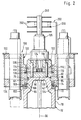
- a multi-spindle machine tool not corresponding to claim 1, 1 as a whole in Fig. 1 includes a Machine frame 12, which is on a base 14 has standing lower part 16.
- This lower part 16 has an outer ring body 18 with a cylindrical outer wall 20 and one of them starting at an angle to the inside sloping drain wall 22.
- the drain wall 22 ends its inner side facing away from the outer wall 20 with a inner ring wall 24 which has an opening of a whole 26 designated swamp encloses, wherein the swarf a bottom 28 sloping in a transverse direction having.
- the outer ring body 18 is preferably symmetrical, in particular rotationally symmetrical, formed to a central axis 30, with the central axis 30 perpendicular to the base 14 stands and pierces it.
- the central axis 30 is a whole with 32 designated stand arranged, which is above the swarf 26 starting from the lower part 16 along the central axis 30 extends.
- the stand 32 includes one Stand foot 34, which extends from this stand foot 34 and radially to the central axis 30 in the direction of Ring body 18 extending and on the drain wall 22nd supporting support walls 36 is worn.
- the stand base 34 forms with the support walls 36 and the ring body 18 in one piece and in one Piece made from the same material.
- the stand base 34 is separated by a parting plane 38, which is preferably runs parallel to the base 14, from one Stand upper part 40 separated, with which the stand 32nd unsupported in the direction of the central axis further from the lower part 16 extends away to a stand head 42.
- the stand 32 comprises a stand tube 44, which one encloses inner cavity 46, down to the chip sump 26 is open through an opening 48 and up through a arranged on the stand head 42 head plate 50 is closed.
- connection between the upper stand part 40 with the Stand head 42 and the stand base 34 in the area of the parting plane 38 is carried out by means of and held on the upper part 40 of the stand bearing eyes 54 protruding outward beyond the stator tube 44, which with corresponding bearing eyes 56, preferably arranged on the stand tube 44 of the stand foot 34 and on the Support walls 36 can be connected, for example by means of screws are.
- the stator tube 44a of the stator upper part also sits 40 butt on the stand tube 44b of the stand base 34.
- stator head 42 provided with a step which is different from a outer circumferential surface 70 of the stator tube 44 radially inwards extending annular flange surface 72 and one this subsequent radially opposite the outer surface 70 recessed cylindrical surface 74 is formed, the latter in the direction of the head plate 50 up to an annular groove 76 extends, which is arranged in the region of the head plate 50 is.
- Ring piston 82 is integrally formed between two in radial direction to the central axis 30 extending groove walls 84 and 86 of the annular groove 76 is movable and thus each one between the annular piston 82 and the respective groove wall 84 or 86 lying cylinder space limited.
- the ring piston 82 By loading one or the other cylinder chamber is the ring piston 82 and thus also the sleeve 80 in one direction displaceable parallel to the central axis 30 relative to the stand head 42.
- the arranged between rings 102 and 104 of a serration is a spindle drum designated as a whole by 100 the central axis 30 is rotatably supported as an axis of rotation.
- the Spindle drum 100 is also non-rotatable with this connected first ring 102 of the serration, which on the second, rotatably connected to the stator head 42 Ring 104 of the Hirth serration guided and opposite this is rotatable, with both rings 102 and 104 in radial Direction to the central axis 30 and in the direction of Have sleeve 80 facing rows of teeth, in which a row of teeth a third ring firmly connected to the sleeve 80 106 can be brought into engagement, the three rings 102, 104 and 106 together form the three-part serration.
- Ring 104 of the serration in the direction of the central axis 30 to determine this is preferably based directly from the flange surface 72 and is also still on the cylinder surface 74 centered in the radial direction.
- the three rings 102, 104, and 106 of the Hirth serration are can be brought into engagement with one another by means of the Sleeve 80 of the third ring 106 with its teeth in the Teeth of the first and second rings 102, 104 pressed the first ring 102 is simultaneously on the second ring 104 on a flange-like support surface 108 supports, so that a total of the three-part serration by means of rings 102, 104 and 106 the spindle drum 100 not only non-rotatable compared to the Stand head 42 is fixable, but also in terms of their Position in the direction parallel to the central axis 30 clearly is set.
- This ring gear 110 is one as planet gears 114 Entire with 116 designated planetary gear, where the planet gears 114 sit on axles 118, on the one hand rotatably in a directly on the head plate 50 overlying lower housing plate 120 and on the other hand non-rotatably are firmly anchored in an upper housing plate 122 and thus the housing plates 120 and 122 in a defined Keep your distance, with the planet gears 114 in recesses from one of the housing plates 120 and 122.
- the planet gears 114 can be driven by a central pinion 124, which is directly on a motor shaft of a drive 126 sits, which is fixed on the upper housing plate 122 and reaches through it with his motor shaft.
- the spindle drum 100 is only over Thrust bearing 128 opposite sleeve 80 and radial bearing 90 stored relative to the stator head 42, while in the rotationally fixed Condition the axial bearing 128 and the radial bearing 90 ineffective are and a fixation and precise positioning of the Spindle drum 100 compared to the stand 32 only over the three Rings 102, 104 and 106 of the serration take place.
- the spindle drum 100 comprises a carrier body 130 with two spaced apart support flanges 132 and 134 which is radially outward from one itself between these protruding inner cylinder 136 and with this one form one-piece part (Fig. 2 and 3).
- the carrier body 130 On the carrier body 130 are in each case the same radial Distances from the axis of rotation or central axis 30 and in constant angular distances with respect to the axis of rotation 30 several, for example eight, spindles 140 arranged, wherein the spindles 140 with their quills 142 quill openings 144 or 146 in the carrier flanges 132, 134.
- the spindles 140 are with their spindle axes 148, like shown in Fig. 3, aligned so that these are parallel run to the axis of rotation 30. Furthermore, the quill 142 are on the carrier flanges 132 and 134 for performing a Z-axis movement opposite the spindle drum 100 in the direction their spindle axes 148 can be moved linearly by means of the Carrier flanges 132 and 134 seated linear guides 150 or 152 stored.
- the ball screw 156 extends with her Spindle section preferably between the two carrier flanges 132 and 134 next to the quill 142 and the drive motor 154 is on one of the ball screw 156 opposite Side of the support flange 134 also next the sleeve 142 and arranged on the carrier flange 134 held.
- a ball screw nut 162 is also located between the two carrier flanges 132 and 134. This sits further in a holder 164 fixed to the sleeve 142, which starts from the quill 142 in the direction of the Ball screw nut 162 extends and preferably this by means of a breakthrough.
- the Holder 164 preferably holds sleeve 142 and carries one Guide body 166, which on a linear guide element 168, preferably one parallel to the spindle axis 148 and to the axis of rotation 30 extending guide rod, is guided, the guide body 166 with the linear guide element 168 an anti-rotation device 170 for in the direction of Spindle axis 148 represents linearly movable quill 142, so that the ball screw 156 free of lateral force in the ball nut 162 runs.
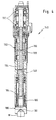
- Each workpiece spindle 140 includes a base 16 facing arranged, for example a workpiece chuck 180 forming workpiece clamping device, which in the quill 142 is rotatably mounted about the spindle axis 148, the workpiece chuck 180 clamping jaws 182 (Fig. 4) for clamping of a workpiece W.
- This workpiece chuck 180 sits on a spindle tube 184, which in turn is rotatably supported in the sleeve 142 via radial bearing 186 and via a runner 188, which together with a fixed in the sleeve 142, preferably in a workpiece chuck 180 opposite area of the same, built-in Stator 190 a built-in motor designated as a whole with 192 forms the rotary drive of the workpiece chuck 180.
- a tensioning tube 194 passing through the spindle tube 184 is provided, which is through the spindle tube 184 and through the Runner 188 extends through and to a hydraulic Clamping cylinder 196 leads, which on one of the chuck 180th opposite end of the quill 142 is arranged.
- this hydraulic clamping cylinder 196 is the workpiece chuck 180 operable in the usual way (Fig. 4).
- the workpiece chucks are 180 on the side of the spindle drum facing the lower part 16 100 arranged so that they are in an upper subspace 198 Work space 200 protrude, which around the stand 32 runs closed in a ring.
- the work space 200 includes furthermore, as shown in FIGS. 1 and 5, still chip generation rooms 201 and loading or unloading rooms 202 or loading and unloading Unloading rooms 203, some of which are below the upper part of the room 198 lie and protrude into the lower part 16, see above that the lower part 16 of the work space 200 still this encloses lower subspaces.
- the carriages 208 are, as shown in FIG. 5, in the radial direction to the spindle axis 148 one in a processing station assigned to this tool 212 stationary workpiece spindle 140 is movable.
- the support desks 204 are preferably from the drain wall 22 molded as a one-piece part.
- each A ball screw 214 is provided on slide 208 which sits a ball screw nut 216.
- the ball screw 214 is in turn connected to a transmission 218 connected to an axle drive motor 220 which is preferably on the opposite side of the slide guide 206
- Carrier desks 204 are arranged below it and in one of the annular body 18 with the outer wall 20 of the drain wall 22 or the support desks 204 and the ring wall 24 enclosed Cavity 222 protrudes.
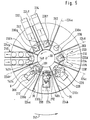
- the chip generation rooms 201 and the loading or unloading rooms 202, 203 are each provided individually on the machine frame and the number of workpiece spindles Spindle stations 230 are assigned and, insofar as they are in the Protrude lower part 16, separated by the support walls 36, each lying in planes 224, which are through the central axis 30 pass through and in the middle, i.e. on the Bisector, between two consecutive Spindle stations 230 are.
- the run Support walls 36 at the same angular distance from each other and their number corresponds to the number of spindle stations 230 (Fig. 5).
- the upper part space 198 is provided with chip protection walls 226, which are in the same planes 224 as the support walls 36 stand when the spindle carrier 100 the workpiece spindles 140 positioned in the spindle stations 230.
- the chip protection walls 226 are stationary in the machine frame 12 held chip protection wall elements 226a and movable, on Spindle carrier 100 held and movable with this chip protection wall elements 226b divided, which corresponds to the in essentially from the stand 32 to an outer work space cover 227 extending chip protection wall 226.
- the processing in the chip production room 201 takes place so that the chips and the cutting means by the action of gravity from down to Chip sump 26 open chip generation space 201 directly in reach the swamp 26.
- Workpiece spindle 140b also takes place, for example Machining, in this case instead of the tool holder 212 a tool turret 224 with several tools 212 is arranged on the carriage 208.
- a replacement and replacement of the workpiece W into the workpiece spindle 140d in the Loading and unloading space 203 there is a workpiece feed belt 232 and a workpiece removal belt 234 are provided, which each linear in the direction of transport 233 or 235 as a whole are movable so that either the workpiece feed belt 232 with its end 236 is able to stand on it Workpiece W for access by the workpiece chuck 180 of the workpiece spindle 140d centered and aligned in parallel to the spindle axis 148 of the same set or the workpiece conveyor belt 234 with its end 238 is able to remove a workpiece W from the workpiece chuck 180 to record the workpiece spindle 140.
- a single workpiece feed belt 232 or workpiece removal belt 234 provided in the respective loading or unloading space 202 runs in to the corresponding spindle station 230f or 230g a workpiece W to take over from the workpiece chuck 180 or to be fed and gripped by the workpiece chuck 180 to provide.
- eighth spindle station 230h is an example of a rotating workpiece feed device 240 shown, which in the loading and Unloading space 203 a workpiece W from the workpiece chuck 180 of the workpiece spindle standing in this spindle station 230h 140h pick up or a workpiece for the access Workpiece chuck 180 can provide.
- the individual workpiece spindles 140a to 140h are through Advancing the spindle drum 100 by a spindle station in the next following spindle station 230b to 230a bringable and by further advancing the spindle drum 100 around a spindle station in the next following spindle station 230c to 230b can be brought, so that in a spindle station, For example, the workpiece is inserted successively for 230 hours processed in the subsequent spindle stations 230a to 230c and removed, for example, in the spindle station 230d can be. At the same time is in the spindle station 230d it is possible to feed another workpiece, which for example also processed in the spindle station 230e can be.
- a supply line 250 which is a flexible segment chain 252 and guided on this flexible Has supply lines 254.
- the supply line 250 is firmly connected at one end 256 to the spindle drum 100 and with an opposite end 258 with a non-rotatable carrier tube 260, which - as in FIG. 1 shown - coaxial to the axis of rotation 30 in continuation of Drive motor 126 on its opposite the planetary gear 116 Side stretches.
- this support tube 260 further extending in planes perpendicular to the axis of rotation 30
- Guide disks 262 at constant intervals from each other arranged, the supply line 250 between two such guide discs 262 in the horizontal direction is led.
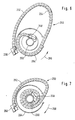
- the supply line 250 is still in a worm housing 264 shown in FIGS. 6 and 7 led, which surrounds the support tube 260, but together is rotatable about the axis 30 with the spindle drum 100.
- the multi-spindle machine tool works in such a way that a work cycle, for example with a Maximum angle of 360 ° -45 ° passes, so that for example the workpiece spindles 140a as they rotate along the Arrow 266 each of the spindle stations 230a to 230h passes through, either processing or loading and Unloading or both occurs and ultimately the workpiece spindle 140a is again in the spindle station 230h.
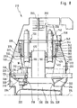
- An embodiment of a multi-spindle machine tool according to the invention, 8 as a whole with 310 denotes a machine frame 312, which a has a base 316 standing base 316.
- This lower part 316 in turn has an outer ring body 318 with a cylindrical outer wall 320 and one starting from this sloping inward drain wall 322 on.
- the drain wall 322 ends on its inner, the Outer wall 320 opposite side with an inner ring wall 324, which has an opening designated 326 as a whole Chip swamp encloses, the chip swamp one in a transverse direction inclined bottom 328.
- the outer ring body 318 is preferably symmetrical, in particular rotationally symmetrical to a central axis 330, the central axis 330 being perpendicular to the base 314 stands and pierces it.
- the support walls 332 form a one-piece with the support ring 336, placed on the lower part 316 and with this connected part of the machine frame 312, which of the Lower part 316 is separated by a parting plane 338.
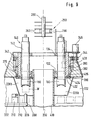
- the support ring 336 encompasses the spindle drum 100 in Area of its outer circumference 340.
- On an outer circumference of the Spindle drum 100 is provided with a ring gear 342 in which has a pinion 344 on the support ring 336 Drive 346 engages, this drive 346 as numerical Controlled final drive is formed.
- a sleeve 380 is provided on the support ring 336, which with an annular piston 382 in a cylinder space engaging annular groove 376 so that the sleeve 380 in same way as the sleeve 80 through the annular piston 382 in the same way as the annular piston 82 parallel to the central axis 330 is displaceable.
- the positioning of the spindle drum 100 is also a three-part serration provided, which has a ring 402 fixed to the spindle drum, which shows a toothing facing the sleeve 380, and one fixed to the support ring 336 ring 404, which also has a toothing facing the sleeve 380, wherein A radial bearing 390 is provided between the two rings 402 and 404 which is for the radial mounting of the spindle drum 100 on the support ring 336 serves.
- the sleeve 380 has a third ring 406 which one of the toothings of the rings 402 and 404 has facing teeth, which with this through Movement of the sleeve 380 is engageable.
- an axial bearing 428 is provided, which in the same way like the thrust bearing 128 for lifting the entire spindle drum 100 with loosened serration is used to - how already in connection with the multi-spindle machine tool 1 to 7 described - the rings 402 and 404 to rotate smoothly relative to each other.
- the support walls 332 extend from the outer Work area cover 227 up to that on the spindle carrier 100 held chip protection wall elements 226b, so that the supporting walls 332 also the function of the multi-spindle machine tool 1 to 7 chip protection wall elements described 226a take over.
- an inner cylinder 410 is provided on the central axis 330, which as protection against the distribution of coolant and chips in serves the subspaces.
- the embodiment is in the same way designed like the multi-spindle machine tool according to FIG. 1 to 7, so that regarding the description of the remaining parts on the explanations of this multi-spindle machine tool full reference is made.
Landscapes
- Engineering & Computer Science (AREA)
- Mechanical Engineering (AREA)
- Machine Tool Units (AREA)
Description
- Fig. 1
- eine Seitenansicht eines vertikalen Schnitts durch ein Ausführungsbeispiel einer nicht dem Anspruch 1 entsprechenden Mehrspindelwerkzeugmaschine;
- Fig. 2
- eine vergrößerte ausschnittsweise Darstellung des Schnitts in Fig. 1 im Bereich eines Ständerkopfes;
- Fig. 3
- eine vergrößerte Darstellung des Schnitts in Fig. 1 im Bereich einer Spindel;
- Fig. 4
- einen Längsschnitt durch eine Spindel des ersten Ausführungsbeispiels;
- Fig. 5
- einen Schnitt längs Linie 5-5 in Fig. 1;
- Fig. 6
- einen Schnitt längs Linie 6-6 in Fig. 1 mit Draufsicht auf einen flexiblen Versorgungsstrang in Ausgangsstellung;
- Fig. 7
- einen Schnitt ähnlich Fig. 6 beim in Endstellung nach einer Drehung um 315° liegendem Versorgungsstrang;
- Fig. 8
- eine Seitenansicht eines vertikalen Schnitts ähnlich Fig. 1 durch ein Ausführungsbeispiel einer erfindungsgemäßen Mehrspindelwerkzeugmaschine und
- Fig. 9
- eine vergrößerte ausschnittsweise Darstellung des Schnitts in Fig. 8 im Bereich eines Lagerrings.
Claims (41)
- Mehrspindelwerkzeugmaschine umfassend ein sich über einer Grundfläche erhebendes Maschinengestell (312), einen am Maschinengestell (312) um eine die Grundfläche (314) durchstoßende und sich von dieser weg erstreckende Drehachse (330) drehbar gelagerten Spindelträger (100), mehrere an dem Spindelträger (100) um die Drehachse (330) herum jeweils einzeln in einzelnen Spindelpositionen hängend angeordnete Werkstückspindeln (140), deren Spindelachsen (148) die Grundfläche (314) durchstoßen und sich von dieser weg erstrecken und die durch Drehen des Spindelträgers (100) um die Drehachse (330) in verschiedenen Drehstellungen positionierbar sind, einen Arbeitsraum (200), in welchen die Werkstückspindeln (140) mit ihren Werkstückspanneinrichtungen (180) hineinragen und ein in dem Arbeitsraum (200) angeordnetes Werkzeug (212), mit welchem ein in der Werkstückspanneinrichtung (180) einer der Werkstückspindeln (140) gespanntes Werkstück (W) bearbeitbar ist, wobei das Maschinengestell (312) ein auf der Grundfläche (314) stehendes Unterteil (316) umfaßt, dadurch gekennzeichnet, daß von dem Unterteil (316), ausgehend sich mindestens drei in radial zur Drehachse (330) und durch diese hindurch verlaufenden Ebenen (224) liegende Tragelemente (332) erheben, die sich bis zu dem Tragring (336) erstrecken und diesen tragen, daß der Tragring (336) den Spindelträger (100) lagert, daß die Werkstückspindeln (140) in ihren Spindelpositionen um die Drehachse (330) herum angeordnet sind und daß radial innerhalb der Tragelemente (332) um die Drehachse (330) herum der Arbeitsraum (200) für die Bearbeitung der in den Werkstückspindeln (140) gehaltenen Werkstücke (W) angeordnet ist.
- Mehrspindelwerkzeugmaschine nach Anspruch 1, dadurch gekennzeichnet, daß die Tragelemente (332) aus flächenhaft sich in den Ebenen (224) erstreckenden Körpern gebildet sind.
- Mehrspindelwerkzeugmaschine nach Anspruch 1 oder 2, dadurch gekennzeichnet, daß die Tragelemente (332) sich ausgehend von einer Umlaufbahn der Werkstückspindeln (140) radial nach außen erstrecken.
- Mehrspindelwerkzeugmaschine nach Anspruch 2 oder 3, dadurch gekennzeichnet, daß die Tragelemente als Tragwände (332) ausgebildet sind.
- Mehrspindelwerkzeugmaschine nach einem der voranstehenden Ansprüche, dadurch gekennzeichnet, daß der Arbeitsraum (200) eine der Zahl der Werkstückspindeln (140) entsprechende Zahl von Stationen (230) aufweist, in welchen die Werkstückspindeln (140) positionierbar sind und daß die Tragelemente (332) jeweils zwischen zwei aufeinanderfolgenden Stationen (230) angeordnet sind.
- Mehrspindelwerkzeugmaschine nach einem der voranstehenden Ansprüche, dadurch gekennzeichnet, daß die Tragelemente (332) in gleichen Winkelabständen voneinander angeordnet sind.
- Mehrspindelwerkzeugmaschine nach einem der voranstehenden Ansprüche, dadurch gekennzeichnet, daß zwischen jeweils zwei aufeinanderfolgenden Stationen (230) eines der Tragelemente (332) angeordnet ist.
- Mehrspindelwerkzeugmaschine nach einem der voranstehenden Ansprüche, dadurch gekennzeichnet, daß die Tragelemente (332) mit dem Tragring (336) sich freitragend über dem Unterteil (316) erheben.
- Mehrspindelwerkzeugmaschine nach einem der voranstehenden Ansprüche, dadurch gekennzeichnet, daß das Unterteil (316) einen radial sich bis zu den Tragelemente (332) erstreckenden und um die Drehachse (330) herum verlaufenden und sich auf der Grundfläche (314) abstützenden Außenkörper (318) umfaßt.
- Mehrspindelwerkzeugmaschine nach Anspruch 9, dadurch gekennzeichnet, daß die Tragelemente (332) mit dem Außenkörper (318) verbunden sind.
- Mehrspindelwerkzeugmaschine nach einem der voranstehenden Ansprüche 1 bis 10, dadurch gekennzeichnet, daß der Spindelträger (100) über ein Lager (390) drehbar gelagert ist, welches radial außerhalb der von den Werkstückspindeln (140) beim Drehen des Spindelträgers (100) beschriebenen Bahnen liegt.
- Mehrspindelwerkzeugmaschine nach Anspruch 11, dadurch gekennzeichnet, daß der Tragring (336) das Lager (390) für den Spindelträger (100) trägt.
- Mehrspindelwerkzeugmaschine nach einem der voranstehenden Ansprüche, dadurch gekennzeichnet, daß der Spindelträger (100) in einer Bearbeitungsstellung zur Bearbeitung der Werkstücke (W) ausschließlich von dem Tragring (336) getragen ist.
- Mehrspindelwerkzeugmaschine nach einem der voranstehenden Ansprüche, dadurch gekennzeichnet, daß ein Drehantrieb (346) für den Spindelträger (100) am Tragring (336) angeordnet ist.
- Mehrspindelwerkzeugmaschine nach Anspruch 14, dadurch gekennzeichnet, daß der Drehantrieb (346) auf dem Tragring (336) angeordnet ist und sich über den Tragring (336) hinaus in Richtung der Drehachse (330) erstreckt.
- Mehrspindelwerkzeugmaschine nach einem der voranstehenden Ansprüche, dadurch gekennzeichnet, daß der Tragring (332) an dem Spindelträger (100) auf einer Außenumfangsseite (340) desselben angreift.
- Mehrspindelwerkzeugmaschine nach einem der voranstehenden Ansprüche, dadurch gekennzeichnet, daß der Tragring (336) den Spindelträger (100) auf seiner Außenumfangsseite (340) umgibt.
- Mehrspindelwerkzeugmaschine nach einem der voranstehenden Ansprüche, dadurch gekennzeichnet, daß die Werkstückspindeln (140) in einzelnen Spindelstationen (230) positionierbar sind und daß mindestens einer der Spindelstationen (230) ein am Maschinengestell (12) gehaltenes Werkzeug (212) zugeordnet ist.
- Mehrspindelwerkzeugmaschine nach Anspruch 18, dadurch gekennzeichnet, daß das Unterteil (16) einen Werkzeugträger (210) für das Werkzeug (212) trägt.
- Mehrspindelwerkzeugmaschine nach Anspruch 19, dadurch gekennzeichnet, daß der Werkzeugträger (210) am Außenkörper (18) des Unterteils (16) angeordnet ist.
- Mehrspindelwerkzeugmaschine nach einem der voranstehenden Ansprüche, dadurch gekennzeichnet, daß das Werkzeug (212) radial zur Spindelachse (148) der jeweiligen Werkstückspindel (140) bewegbar ist.
- Mehrspindelwerkzeugmaschine nach Anspruch 21, dadurch gekennzeichnet, daß das Werkzeug (212) durch eine NC-gesteuerte X-Achse radial zur Spindelachse (140) bewegbar und positionierbar ist.
- Mehrspindelwerkzeugmaschine nach einem der voranstehenden Ansprüche, dadurch gekennzeichnet, daß die Werkstückspindeln (140) in Richtung ihrer Spindelachse (148) relativ zum Spindelträger (100) linear bewegbar sind.
- Mehrspindelwerkzeugmaschine nach Anspruch 23, dadurch gekennzeichnet, daß die in Richtung ihrer Spindelachsen (148) verschiebbaren Werkstückspindeln (140) eine numerisch gesteuerte Z-Achse zur Bearbeitung des Werkstücks (W) bilden.
- Mehrspindelwerkzeugmaschine nach Anspruch 23 oder 24, dadurch gekennzeichnet, daß die Werkstückspindeln (140) relativ zum Spindelträger (100) ausschließlich in Richtung ihrer Spindelachse (148) linear bewegbar sind.
- Mehrspindelwerkzeugmaschine nach einem der Ansprüche 23 bis 25, dadurch gekennzeichnet, daß die Werkstückspindeln (140) relativ zum Spindelträger (100) in Richtung ihrer Spindelachse (148) unabhängig voneinander bewegbar sind.
- Mehrspindelwerkzeugmaschine nach Anspruch 26, dadurch gekennzeichnet, daß jeder Werkstückspindel (140) ein eigener Linearantrieb (154, 156, 162) zur Bewegung derselben in Richtung der Spindelachse (148) zugeordnet ist.
- Mehrspindelwerkzeugmaschine nach Anspruch 27, dadurch gekennzeichnet, daß jede Werkstückspindel (140) ständig mit dem Linearantrieb (154, 156, 162) gekoppelt ist.
- Mehrspindelwerkzeugmaschine nach Anspruch 27 oder 28, dadurch gekennzeichnet, daß jede Werkstückspindel (140) bezüglich ihrer Position in Richtung der Spindelachse (148) mittels des Linearantriebs (154, 156, 162) definiert positionierbar und fixierbar ist.
- Mehrspindelwerkzeugmaschine nach einem der Ansprüche 27 bis 29, dadurch gekennzeichnet, daß der Linearantrieb (154, 156, 162) an dem Spindelträger (100) sitzt.
- Mehrspindelwerkzeugmaschine nach Anspruch 30, dadurch gekennzeichnet, daß ein Linearantrieb (154, 156, 162) an dem Spindelträger (100) bezogen auf die jeweilige Werkstückspindel (140) radial außen liegend angeordnet ist.
- Mehrspindelwerkzeugmaschine nach Anspruch 30 oder 31, dadurch gekennzeichnet, daß der Linearantrieb (154, 156, 162) in einem Winkelbereich zwischen zwei aufeinanderfolgenden Werkstückspindeln (140) angeordnet ist.
- Mehrspindelwerkzeugmaschine nach Anspruch 32, dadurch gekennzeichnet, daß der Linearantrieb (154, 156, 162) bezüglich zweier aufeinanderfolgender Werkstückspindeln (140) auf Lücke angeordnet ist.
- Mehrspindelwerkzeugmaschine nach einem der voranstehenden Ansprüche, dadurch gekennzeichnet, daß jede Werkstückspindel (140) als Motorspindel ausgebildet ist.
- Mehrspindelwerkzeugmaschine nach einem der voranstehenden Ansprüche dadurch gekennzeichnet, daß der Arbeitsraum (200) einen Bewegungsraum (198) für die Werkstückspindeln (140) umfaßt, welcher in sich geschlossen und durchgehend rings um die Mittelachse (30) herum verläuft.
- Mehrspindelwerkzeugmaschine nach einem der voranstehenden Ansprüche, dadurch gekennzeichnet, daß der Arbeitsraum (200) einen mindestens einer Spindelstation (230) zugeordneten Spanerzeugungsraum (201) umfaßt.
- Mehrspindelwerkzeugmaschine nach einem der voranstehenden Ansprüche, dadurch gekennzeichnet, daß der Arbeitsraum (200) einen mindestens einer Spindelstation (230) zugeordneten Be- oder Entladeraum (202) oder einen einer Spindelstation zugeordneten Be- und Entladeraum (203) umfaßt
- Mehrspindelwerkzeugmaschine nach Anspruch 36 oder 37 dadurch gekennzeichnet, daß zwischen dem jeder Spindelstation (230) zugeordneten Raum (201, 202, 203) eine Wand (36) angeordnet ist.
- Mehrspindelwerkzeugmaschine nach einem der voranstehenden Ansprüche, dadurch gekennzeichnet, daß mindestens ein Teil der Spindelstation (230) als Bearbeitungsstationen ausgebildet ist.
- Mehrspindelwerkzeugmaschine nach einem der voranstehenden Ansprüche, dadurch gekennzeichnet, daß mindestens ein Teil der Spindelstation (230) als Be- oder Entladestationen (202) oder als Be- und Entladestationen (203) ausgebildet ist.
- Mehrspindelwerkzeugmaschine nach einem der voranstehenden Ansprüche, dadurch gekennzeichnet, daß der Spindelträger (100) von einer Ausgangsstellung um einen Maximalwinkel in einer Richtung (266) bis zu einer Endstellung und dann wieder in entgegengesetzter Richtung (268) zurück in die Ausgangsstellung drehbar ist und vom Maschinengestell (12) zum Spindelträger (100) ein flexibler Versorgungsstrang (250) geführt ist, welcher der Drehbewegung um den Maximalwinkel folgt.
Priority Applications (1)
| Application Number | Priority Date | Filing Date | Title |
|---|---|---|---|
| EP01124486A EP1180413B1 (de) | 1995-02-10 | 1996-02-09 | Mehrspindelwerkzeugmaschine |
Applications Claiming Priority (2)
| Application Number | Priority Date | Filing Date | Title |
|---|---|---|---|
| DE19504369 | 1995-02-10 | ||
| DE19504369A DE19504369A1 (de) | 1995-02-10 | 1995-02-10 | Mehrspindelwerkzeugmaschine |
Related Child Applications (1)
| Application Number | Title | Priority Date | Filing Date |
|---|---|---|---|
| EP01124486A Division EP1180413B1 (de) | 1995-02-10 | 1996-02-09 | Mehrspindelwerkzeugmaschine |
Publications (2)
| Publication Number | Publication Date |
|---|---|
| EP0726119A1 EP0726119A1 (de) | 1996-08-14 |
| EP0726119B1 true EP0726119B1 (de) | 2002-06-05 |
Family
ID=7753602
Family Applications (2)
| Application Number | Title | Priority Date | Filing Date |
|---|---|---|---|
| EP96101881A Expired - Lifetime EP0726119B1 (de) | 1995-02-10 | 1996-02-09 | Mehrspindelwerkzeugmaschine |
| EP01124486A Expired - Lifetime EP1180413B1 (de) | 1995-02-10 | 1996-02-09 | Mehrspindelwerkzeugmaschine |
Family Applications After (1)
| Application Number | Title | Priority Date | Filing Date |
|---|---|---|---|
| EP01124486A Expired - Lifetime EP1180413B1 (de) | 1995-02-10 | 1996-02-09 | Mehrspindelwerkzeugmaschine |
Country Status (5)
| Country | Link |
|---|---|
| US (1) | US5697270A (de) |
| EP (2) | EP0726119B1 (de) |
| JP (1) | JPH0994726A (de) |
| DE (3) | DE19504369A1 (de) |
| ES (1) | ES2177687T3 (de) |
Cited By (1)
| Publication number | Priority date | Publication date | Assignee | Title |
|---|---|---|---|---|
| CN102985218A (zh) * | 2010-04-26 | 2013-03-20 | 托尔诺斯有限公司 | 机床转塔的分度 |
Families Citing this family (34)
| Publication number | Priority date | Publication date | Assignee | Title |
|---|---|---|---|---|
| EP0839601A1 (de) * | 1996-11-04 | 1998-05-06 | K.R. Pfiffner Ag | Werkzeugmaschine |
| DE19648810A1 (de) * | 1996-11-26 | 1998-05-28 | Bad Dueben Profilwalzmaschinen | Lade- und Wendeeinrichtung für eine Drehmaschine mit hängender Tamdemspindel |
| EP0937539A1 (de) * | 1998-02-24 | 1999-08-25 | Mikron SA Agno | Rundtaktmaschine |
| DE19835868B4 (de) * | 1998-08-07 | 2010-01-21 | Helmut Schuster | Vorrichtung aus vertikal angeordneten Drehmaschinen |
| DE19835954A1 (de) * | 1998-08-08 | 2000-02-17 | Index Werke Kg Hahn & Tessky | Werkzeugmaschine |
| JP3636895B2 (ja) * | 1998-09-02 | 2005-04-06 | 株式会社森精機ハイテック | 主軸移動型立形工作機械用の棒状工作物供給装置および主軸移動型立形工作機械における棒状工作物供給方法 |
| DE19841449A1 (de) * | 1998-09-10 | 2000-03-23 | Index Werke Kg Hahn & Tessky | Werkzeugmaschine |
| DE19843575B4 (de) * | 1998-09-23 | 2005-05-12 | Alfred H. Schütte GmbH & Co. KG | Mehrspindelige Werkzeugmaschine, insbesondere Mehrspindeldrehautomat |
| DE19904253A1 (de) * | 1999-02-03 | 2000-08-10 | Index Werke Kg Hahn & Tessky | Werkzeugmaschine |
| DE19916212C2 (de) * | 1999-04-10 | 2003-07-10 | Schuette Alfred H Gmbh & Co Kg | Mehrspindelige Werkzeugmaschine, insbesondere Mehrspindeldrehautomat |
| AUPQ120499A0 (en) * | 1999-06-25 | 1999-07-22 | K D Binnie Engineering Pty Ltd (As Trustees For K D Binnie Engineering Superannuation Fund) | A lathe |
| SE515304C2 (sv) * | 1999-11-08 | 2001-07-09 | Hydropulsor Ab | Enkelt monterbar och demonterbar maskin |
| EP1106304B1 (de) * | 1999-12-01 | 2006-03-08 | Index-Werke Gmbh & Co. Kg Hahn & Tessky | Werkzeugmaschine |
| EP1251994B1 (de) * | 2000-02-01 | 2008-08-06 | Emmegi S.A. Luxembourg, Lugano Branch | Bearbeitungssystem |
| EP1205279A1 (de) * | 2000-11-08 | 2002-05-15 | IEMCA Giuliani Macchine Italia S.p.A. | Werkzeugmaschine mit Rundschalttisch |
| DE10153807A1 (de) * | 2001-11-05 | 2003-05-28 | Emag Maschfab Gmbh | Werkzeugmaschine |
| DE10160280B4 (de) * | 2001-12-07 | 2011-05-26 | Thielenhaus Technologies Gmbh | Vorrichtung zur mechanischen Oberflächenbearbeitung von Werkstücken |
| DE10226272A1 (de) * | 2002-06-07 | 2004-01-08 | Index-Werke Gmbh & Co. Kg Hahn & Tessky | Mehrspindelwerkzeugmaschine |
| DE10333051A1 (de) * | 2003-07-18 | 2005-02-03 | Grob-Werke Burkhart Grob E.K. | Spanabhebende Bearbeitungsmaschine |
| TW200536725A (en) * | 2004-01-17 | 2005-11-16 | Sanford Lp | Writing instrument with a tape flag dispenser |
| DE102005015649B4 (de) * | 2005-04-05 | 2007-07-05 | Emag Holding Gmbh | Verfahren zum Drehen und Feinstbearbeiten eines Werkstückes und Vorrichtung zur Durchführung des Verfahrens |
| US20070006447A1 (en) * | 2005-05-20 | 2007-01-11 | Webster M C | Automated continuous operation tube forming system |
| DE202005015906U1 (de) * | 2005-10-07 | 2007-02-15 | Alfred H. Schütte GmbH & Co. KG | Mehrspindeldrehmaschine |
| IT1396170B1 (it) * | 2008-09-11 | 2012-11-16 | Gildemeister Spa | Macchina tornitrice plurimandrino con mandrini portapezzo movibili in direzione longitudinale all'asse macchina |
| ITTO20090809A1 (it) | 2009-10-23 | 2011-04-24 | Siecab S R L | Stazione di lavoro perfezionata per lavorazioni ad asportazione di truciolo |
| IT1399706B1 (it) * | 2010-04-09 | 2013-04-26 | Danieli Off Mecc | Macchina per la filettatura di manicotti o simili, e relativo procedimento |
| DE102011053504A1 (de) * | 2011-09-12 | 2013-03-14 | Index-Werke Gmbh & Co. Kg Hahn & Tessky | Mehrspindeldrehmaschine |
| ITBS20110133A1 (it) * | 2011-09-28 | 2013-03-29 | Gnutti Transfer S P A | Macchina utensile con dispositivo di supporto ed afferraggio di una pluralità di pezzi meccanici |
| ITBS20110132A1 (it) | 2011-09-28 | 2013-03-29 | Gnutti Transfer S P A | Macchina utensile con un corpo principale avente una tavola mobile rotabile che supporta i pezzi |
| DE202011108153U1 (de) * | 2011-11-21 | 2012-02-02 | Deckel Maho Pfronten Gmbh | Vorrichtung zum Einsatz in einer Werkzeugmaschine sowie Werkzeugmaschine |
| ITTO20121148A1 (it) * | 2012-12-27 | 2014-06-28 | Siecab S R L | Tornio verticale con mandrino pick-up mobile lungo una traiettoria circolare |
| US8944802B2 (en) | 2013-01-25 | 2015-02-03 | Radiant Fabrication, Inc. | Fixed printhead fused filament fabrication printer and method |
| US8827684B1 (en) | 2013-12-23 | 2014-09-09 | Radiant Fabrication | 3D printer and printhead unit with multiple filaments |
| EP3417995B8 (de) * | 2017-06-21 | 2024-03-27 | DMG MORI Bergamo S.r.l. | Werkzeugmaschine, insbesondere mehrspindlige drehmaschine |
Family Cites Families (14)
| Publication number | Priority date | Publication date | Assignee | Title |
|---|---|---|---|---|
| US1574726A (en) * | 1921-01-29 | 1926-02-23 | Bullard Machine Tool Co | Multiple-spindle-machine tool |
| US1671354A (en) * | 1926-08-10 | 1928-05-29 | Leeuw Adolph L De | Inverted unitary chucking machine |
| US1743862A (en) * | 1927-09-17 | 1930-01-14 | James J Morris | Multiple-spindle rotary turning machine |
| US2044496A (en) * | 1931-08-11 | 1936-06-16 | Bullard Co | Stationary tool metal working apparatus |
| US2032646A (en) * | 1932-01-02 | 1936-03-03 | Cleveland Hobbing Machine Co | Multiple spindle hobbing machine |
| DE950525C (de) * | 1943-11-23 | 1956-11-22 | Messerschmitt Boelkow Blohm | Werkzeugmaschine |
| DE2012461A1 (de) * | 1970-03-17 | 1971-10-07 | Brandis H | Mehrspindehge Nachdrehmaschine zur Bearbeitung von Großsenenteilen |
| DE2036766C3 (de) * | 1970-07-24 | 1975-09-04 | Nautschno-Issledowatelskij Institut Technologii Awtomobilnoj Promyschlennosti, Moskau | Senkrechter-Mehrspindel-Drehautomat |
| US3792633A (en) * | 1973-04-02 | 1974-02-19 | V Kogtev | Vertical multispindle continuous lathe |
| BR8108057A (pt) * | 1981-12-11 | 1983-09-13 | Romi Ind | Maquina de tornear |
| JPS58202744A (ja) * | 1982-03-10 | 1983-11-26 | レニシヨウ パブリツク リミテツド カンパニ− | 工作機械 |
| DE3416660A1 (de) * | 1984-05-05 | 1985-11-07 | J.G. Weisser Söhne Werkzeugmaschinenfabrik GmbH & Co. KG, 7742 St Georgen | Drehmaschine |
| DE3844337A1 (de) * | 1988-12-30 | 1990-07-05 | Index Werke Kg Hahn & Tessky | Werkzeugmaschine mit gekuehlter motorspindel |
| US5127140A (en) * | 1989-12-18 | 1992-07-07 | Hitachi Seiki Co., Ltd. | Numerically-controlled lathe, numerically-controlled device therefor and processing procedure thereby |
-
1995
- 1995-02-10 DE DE19504369A patent/DE19504369A1/de not_active Withdrawn
- 1995-09-08 US US08/525,479 patent/US5697270A/en not_active Expired - Fee Related
-
1996
- 1996-02-09 DE DE59609271T patent/DE59609271D1/de not_active Expired - Fee Related
- 1996-02-09 DE DE59611226T patent/DE59611226D1/de not_active Expired - Fee Related
- 1996-02-09 EP EP96101881A patent/EP0726119B1/de not_active Expired - Lifetime
- 1996-02-09 ES ES96101881T patent/ES2177687T3/es not_active Expired - Lifetime
- 1996-02-09 EP EP01124486A patent/EP1180413B1/de not_active Expired - Lifetime
- 1996-02-13 JP JP8025381A patent/JPH0994726A/ja active Pending
Cited By (1)
| Publication number | Priority date | Publication date | Assignee | Title |
|---|---|---|---|---|
| CN102985218A (zh) * | 2010-04-26 | 2013-03-20 | 托尔诺斯有限公司 | 机床转塔的分度 |
Also Published As
| Publication number | Publication date |
|---|---|
| DE59609271D1 (de) | 2002-07-11 |
| EP1180413B1 (de) | 2005-05-04 |
| EP1180413A2 (de) | 2002-02-20 |
| DE59611226D1 (de) | 2005-06-09 |
| EP0726119A1 (de) | 1996-08-14 |
| JPH0994726A (ja) | 1997-04-08 |
| DE19504369A1 (de) | 1996-08-14 |
| ES2177687T3 (es) | 2002-12-16 |
| EP1180413A3 (de) | 2003-03-12 |
| US5697270A (en) | 1997-12-16 |
Similar Documents
| Publication | Publication Date | Title |
|---|---|---|
| EP1180413B1 (de) | Mehrspindelwerkzeugmaschine | |
| EP0538515B1 (de) | Drehmaschine | |
| DE60211511T2 (de) | Rundtaktwerkzeugmaschine zur bearbeitung von werkstücken | |
| EP1193027B1 (de) | Drehmaschine | |
| EP1886763B1 (de) | Werkzeugmagazin für eine Werkzeugmaschine | |
| DE4301393C2 (de) | Rundtakt-Werkzeugmaschine | |
| EP1886764B1 (de) | Werkzeugmaschine | |
| EP1046461A2 (de) | Universal-Werkzeugmaschine | |
| DE19504368A1 (de) | Werkzeugmaschine | |
| EP1570946B1 (de) | Werkzeugmaschine mit mindestens zwei Werkzeugspindeln und einer Werkzeugmagazinscheibe | |
| EP0885686A1 (de) | Bearbeitungszelle | |
| EP0807490B1 (de) | Mehrspindeldrehmaschine | |
| EP1270145A2 (de) | Werkzeugmaschine mit einem drehbaren Mehrfachwerkzeugträger | |
| DE4236866A1 (de) | Drehmaschine | |
| EP1160052B1 (de) | Drehmaschine | |
| DE3532538C1 (de) | Vorrichtung zum Raeumen von zylindrischen Flaechen eines Werkstueckes,vorzugsweise von Lagerzapfen,insbesondere einer Kurbelwelle | |
| DE2836598C2 (de) | Drehmaschine mit zum gleichzeitigen Bearbeiten der gleichachsigen Wellenzapfen einer Kurbelwelle dienenden Aufiendrehwerkzeugen | |
| EP2602053A1 (de) | Werkzeugmaschine | |
| EP0755315B1 (de) | Mehrspindeldrehmaschine | |
| DE19652460C1 (de) | Werkzeugmaschine mit mehreren Spindeln | |
| DE3530982A1 (de) | Zweispindlige, numerisch gesteuerte drehmaschine | |
| DE19607883A1 (de) | Vertikal-Drehmaschine | |
| EP2602054B1 (de) | Werkzeugmaschine | |
| DE1966960A1 (de) | Automatische mehrfachspindelstangenmaschine | |
| DE19534167C1 (de) | CNC-Bearbeitungszentrum mit einem Werkzeugrevolver |
Legal Events
| Date | Code | Title | Description |
|---|---|---|---|
| PUAI | Public reference made under article 153(3) epc to a published international application that has entered the european phase |
Free format text: ORIGINAL CODE: 0009012 |
|
| AK | Designated contracting states |
Kind code of ref document: A1 Designated state(s): CH DE ES FR GB IT LI |
|
| 17P | Request for examination filed |
Effective date: 19960905 |
|
| 17Q | First examination report despatched |
Effective date: 19971013 |
|
| GRAG | Despatch of communication of intention to grant |
Free format text: ORIGINAL CODE: EPIDOS AGRA |
|
| GRAG | Despatch of communication of intention to grant |
Free format text: ORIGINAL CODE: EPIDOS AGRA |
|
| GRAH | Despatch of communication of intention to grant a patent |
Free format text: ORIGINAL CODE: EPIDOS IGRA |
|
| GRAH | Despatch of communication of intention to grant a patent |
Free format text: ORIGINAL CODE: EPIDOS IGRA |
|
| GRAA | (expected) grant |
Free format text: ORIGINAL CODE: 0009210 |
|
| AK | Designated contracting states |
Kind code of ref document: B1 Designated state(s): CH DE ES FR GB IT LI |
|
| REG | Reference to a national code |
Ref country code: GB Ref legal event code: FG4D Free format text: NOT ENGLISH |
|
| REG | Reference to a national code |
Ref country code: CH Ref legal event code: EP |
|
| REF | Corresponds to: |
Ref document number: 59609271 Country of ref document: DE Date of ref document: 20020711 |
|
| REG | Reference to a national code |
Ref country code: CH Ref legal event code: NV Representative=s name: KIRKER & CIE SA |
|
| GBT | Gb: translation of ep patent filed (gb section 77(6)(a)/1977) |
Effective date: 20020721 |
|
| ET | Fr: translation filed | ||
| REG | Reference to a national code |
Ref country code: ES Ref legal event code: FG2A Ref document number: 2177687 Country of ref document: ES Kind code of ref document: T3 |
|
| PLBE | No opposition filed within time limit |
Free format text: ORIGINAL CODE: 0009261 |
|
| STAA | Information on the status of an ep patent application or granted ep patent |
Free format text: STATUS: NO OPPOSITION FILED WITHIN TIME LIMIT |
|
| 26N | No opposition filed |
Effective date: 20030306 |
|
| PGFP | Annual fee paid to national office [announced via postgrant information from national office to epo] |
Ref country code: GB Payment date: 20050127 Year of fee payment: 10 |
|
| PGFP | Annual fee paid to national office [announced via postgrant information from national office to epo] |
Ref country code: FR Payment date: 20050222 Year of fee payment: 10 |
|
| PG25 | Lapsed in a contracting state [announced via postgrant information from national office to epo] |
Ref country code: GB Free format text: LAPSE BECAUSE OF NON-PAYMENT OF DUE FEES Effective date: 20060209 |
|
| GBPC | Gb: european patent ceased through non-payment of renewal fee |
Effective date: 20060209 |
|
| REG | Reference to a national code |
Ref country code: FR Ref legal event code: ST Effective date: 20061031 |
|
| PG25 | Lapsed in a contracting state [announced via postgrant information from national office to epo] |
Ref country code: FR Free format text: LAPSE BECAUSE OF NON-PAYMENT OF DUE FEES Effective date: 20060228 |
|
| PGFP | Annual fee paid to national office [announced via postgrant information from national office to epo] |
Ref country code: ES Payment date: 20080212 Year of fee payment: 13 |
|
| PGFP | Annual fee paid to national office [announced via postgrant information from national office to epo] |
Ref country code: DE Payment date: 20080327 Year of fee payment: 13 |
|
| PGFP | Annual fee paid to national office [announced via postgrant information from national office to epo] |
Ref country code: IT Payment date: 20090205 Year of fee payment: 14 |
|
| PG25 | Lapsed in a contracting state [announced via postgrant information from national office to epo] |
Ref country code: DE Free format text: LAPSE BECAUSE OF NON-PAYMENT OF DUE FEES Effective date: 20090901 |
|
| REG | Reference to a national code |
Ref country code: ES Ref legal event code: FD2A Effective date: 20090210 |
|
| PG25 | Lapsed in a contracting state [announced via postgrant information from national office to epo] |
Ref country code: ES Free format text: LAPSE BECAUSE OF NON-PAYMENT OF DUE FEES Effective date: 20090210 |
|
| PG25 | Lapsed in a contracting state [announced via postgrant information from national office to epo] |
Ref country code: IT Free format text: LAPSE BECAUSE OF NON-PAYMENT OF DUE FEES Effective date: 20100209 |
|
| PGFP | Annual fee paid to national office [announced via postgrant information from national office to epo] |
Ref country code: CH Payment date: 20110214 Year of fee payment: 16 |
|
| REG | Reference to a national code |
Ref country code: CH Ref legal event code: PL |
|
| PG25 | Lapsed in a contracting state [announced via postgrant information from national office to epo] |
Ref country code: LI Free format text: LAPSE BECAUSE OF NON-PAYMENT OF DUE FEES Effective date: 20120229 Ref country code: CH Free format text: LAPSE BECAUSE OF NON-PAYMENT OF DUE FEES Effective date: 20120229 |