EP0725410B1 - Drehstellbares Bauelement mit einer Rasteinrichtung - Google Patents
Drehstellbares Bauelement mit einer Rasteinrichtung Download PDFInfo
- Publication number
- EP0725410B1 EP0725410B1 EP95117658A EP95117658A EP0725410B1 EP 0725410 B1 EP0725410 B1 EP 0725410B1 EP 95117658 A EP95117658 A EP 95117658A EP 95117658 A EP95117658 A EP 95117658A EP 0725410 B1 EP0725410 B1 EP 0725410B1
- Authority
- EP
- European Patent Office
- Prior art keywords
- latching
- leaf
- extension
- type spring
- rotor
- Prior art date
- Legal status (The legal status is an assumption and is not a legal conclusion. Google has not performed a legal analysis and makes no representation as to the accuracy of the status listed.)
- Expired - Lifetime
Links
Images


Classifications
-
- H—ELECTRICITY
- H01—ELECTRIC ELEMENTS
- H01H—ELECTRIC SWITCHES; RELAYS; SELECTORS; EMERGENCY PROTECTIVE DEVICES
- H01H19/00—Switches operated by an operating part which is rotatable about a longitudinal axis thereof and which is acted upon directly by a solid body external to the switch, e.g. by a hand
- H01H19/02—Details
- H01H19/10—Movable parts; Contacts mounted thereon
- H01H19/11—Movable parts; Contacts mounted thereon with indexing means
-
- G—PHYSICS
- G05—CONTROLLING; REGULATING
- G05G—CONTROL DEVICES OR SYSTEMS INSOFAR AS CHARACTERISED BY MECHANICAL FEATURES ONLY
- G05G5/00—Means for preventing, limiting or returning the movements of parts of a control mechanism, e.g. locking controlling member
- G05G5/06—Means for preventing, limiting or returning the movements of parts of a control mechanism, e.g. locking controlling member for holding members in one or a limited number of definite positions only
-
- H—ELECTRICITY
- H01—ELECTRIC ELEMENTS
- H01C—RESISTORS
- H01C1/00—Details
- H01C1/14—Terminals or tapping points specially adapted for resistors; Arrangements of terminals or tapping points on resistors
Definitions
- the invention relates to a rotatable electrical component, in particular rotary switch or rotary resistor with a latching device, according to the preamble of claim 1 (DE-A-2 735 352).
- a locking device makes it easier to find operating positions, it is tactile and sometimes acoustically perceptible during turning. In the case of resistors in particular, the adjustment is perceptible and thus conscious by a latching device.
- the latching means of a latching device essentially consist of a spring-elastic latching projection, latching nose for short, and one or more adjacent latching depressions which form a latching contour which interacts with the latching nose.
- One of the two locking means, locking lug or locking contour is rotatably connected to an actuator of the component in question.
- the respective other locking means is held stationary on the component.
- the two latching means which are weighted against each other by a spring element, slide relative to one another when they are turned.
- the locking means generate tactile locking marks.
- DE 31 39 094 A1 shows a rotational resistance with locking means arranged radially to the axis of rotation.
- the resilient locking lug is held stationary and the locking contour can be rotated.
- rotary resistors are known with locking means arranged coaxially with the axis of rotation.
- the resilient locking lug is also held stationary and the locking contour can be rotated (DE 27 35 352 A1, US 2 632 830).
- the resilient latching lug is rotatable and the latching contour is stationary (DE 2 755 999, DE 36 37 597 A1).
- a locking device is shown with a leaf spring as a spring element.
- the leaf spring is shaped at one end as a locking lug that interacts with a locking contour.
- leaf spring with the latching lug formed thereon can be inserted into the arrangement of the latching device in a self-retaining manner.
- Another advantage is improved acoustic perceptibility of the locking device during the turning position. The less wide extension of the leaf spring is tensioned against the side limit of an associated clearance that takes place at the pivoting points. While the latch is latching, the extension relaxes momentarily and strikes against an opposite side limit in the direction of rotation.
- Figure 1 shows the drive end of a rotatable component with an integrated locking device.
- the component (1) itself is only hinted at.
- a rotor (3) is located in a housing (2).
- the rotor (3) can be rotated by an adjusting shaft (4).
- the rotor (3) and the adjusting shaft (4) are rotatably supported in the housing (2).
- the rotor (3) carries a coupling part (5) towards the component (1) for transmitting the actuating movement to the component.
- Other arrangements of the latching device are conceivable in which the rotor (3) provides the component (1) directly.
- the rotor (3) is essentially a hollow cylinder, it has a cylinder bottom (6) and a stepped cylinder wall (7).
- the rotor (3) is open to the component (1); in the example, the attached coupling part (5) covers the rotor (3).
- a leaf spring (8) is clamped between its ends on diametrically located parts of the cylinder wall (7) in such a way that its shape is essentially U-shaped.
- the U-arm extends towards the component.
- the leaf spring (8) has a bluntly cut end (9) (Fig. 3a), which is bent back on the outside towards the leaf spring (8) in a recess (10) on the cylinder wall (7).
- the opposite end (11) of the leaf spring (8) is formed by symmetrically cut-free contact shoulders (12), which are supported on a divided step-like shoulder (13).
- the leaf spring (8) continues in an extension (14) between the contact shoulders (12).
- a detent (15) is formed on the extension (14).
- the extension is bent back so far towards the leaf spring (8) that in the installed state the locking lug (15) and contact shoulders (12) are able to spring radially to the axis of rotation (16) of the rotor (3).
- the extension (14) extends through the cylinder wall (7) through a window-like opening (17) to such an extent that the locking lug (15) comes to lie outside the cylinder wall (7).
- the leaf spring (8) is laterally guided on the ribs (18) in the region of its end sections; This means that it is positioned exactly and cannot move sideways.
- the extension (14) within the opening (17) is movable within limits; the opening (17) is a quarter to a half tooth pitch of the locking contour (19) (see FIG. 2) wider than the width of the extension.
- the leaf spring (8) is exposed between its end sections (9, 11). The leaf spring (8) is secured against falling out of its desired position by stop surfaces (23, 24).
- a locking contour (19) is incorporated in the housing. It consists of a series of tooth-like recesses, not shown, in more detail.
- the locking contour (19) is located at the height of the locking lug (15), which engages in the opposite locking recess.
- the locking lug (15) springs the contact shoulders (12) radially inwards, so that there is a distance to the inner wall (20) of the rotor (3) on the contact shoulders. If the rotor is removed from the housing (2), the contact shoulders (12) rest on the inner wall (20) of the rotor.
- the less precisely guided extension (14) initially twists and is pushed by a side wall (21) of the opening (17).
- the latching lug snaps into a recess in the latching contour (19)
- the extension (14) relaxes momentarily and strikes the opposite side wall (22). The striking is audible.
- the acoustic perceptibility is further improved by sound spaces that would have to be created when the arrangement was installed in a device.
Landscapes
- Engineering & Computer Science (AREA)
- Microelectronics & Electronic Packaging (AREA)
- Physics & Mathematics (AREA)
- General Physics & Mathematics (AREA)
- Automation & Control Theory (AREA)
- Rotary Switch, Piano Key Switch, And Lever Switch (AREA)
- Snaps, Bayonet Connections, Set Pins, And Snap Rings (AREA)
- Lock And Its Accessories (AREA)
Description
- Die Erfindung betrifft ein drehstellbares elektrisches Bauelement, insbesondere Drehschalter oder Drehwiderstand mit einer Rasteinrichtung, gemäß dem Oberbegriff des Anspruches 1 (DE-A-2 735 352).
- Eine Rasteinrichtung erleichtert das Auffinden von Betriebspositionen, sie ist während des Drehstellens taktil und mitunter auch akkustisch wahrnehmbar. Insbesondere bei Widerständen wird das Verstellen durch eine Rasteinrichtung spürbar und damit bewußt.
- Die Rastmittel einer Rasteinrichtung bestehen im wesentlichen aus einem federelastisch gehaltenen Rastvorsprung, kurz Rastnase, und aus einer oder mehreren benachbarten Rastvertiefungen, die eine mit der Rastnase zusammenwirkende Rastkontur ausbilden. Eines der beiden Rastmittel, Rastnase bzw. Rastkontur ist drehfest mit einem Stellglied des betreffenden Bauelementes verbunden. Das jeweilige andere Rastmittel ist demgegenüber am Bauelement ortsfest gehalten. Die beiden Rastmittel, die von einem Federelement beschwert gegeneinander liegen, gleiten beim Drehstellen zueinander relativ. Dabei erzeugen die Rastmittel taktile Rastmarken.
- In der DE 31 39 094 A1 ist ein Drehwiderstand angezeigt mit radial zur Drehachse angeordneten Rastmittel. Dabei ist die federnde Rastnase ortsfest gehalten und die Rastkontur ist drehstellbar.
- Desweiteren sind Drehwiderstände bekannt mit zur Drehachse koaxial angeordneten Rastmitteln. Bei einem Teil dieser Drehwiderstände ist die federnde Rastnase ebenfalls ortsfest gehalten und die Rastkontur drehstellbar (DE 27 35 352 A1, US 2 632 830). Bei einem anderen Teil dieser Drehwiderstände ist die federnde Rastnase drehstellbar und die Rastkontur ortsfest (DE 2 755 999, DE 36 37 597 A1).
- Die DE 40 35 011 A1 beschreibt die Rasteinrichtung eines Drehschalters. Dabei steht ein drehstellbarer Magnetring mit Polen wechselnder Polarität einem weichmagnetischen Stator mit Polschuhen gegenüber.
- In dem Buch 'Bauelemente der Feinmechanik', Verlag Technik Berlin, 6. Auflage, Fig. 1139, ist eine Rasteinrichtung dargestellt mit einer Blattfeder als Federelement. Die Blattfeder ist an ihrem einen Ende als Rastnase geformt, die mit einer Rastkontur zusammenwirkt.
- Es ist Aufgabe der Erfindung eine Rasteinrichtung der eigangs bezeichneten Art vorzuschlagen bei der das Federelement einen relativ zur Baugröße großen Federweg der Rastnase zuläßt. Die Aufgabe wird durch die Merkmale des Anspruches 1 gelöst. Vorteilhafte Weiterentwicklungen ergeben sich aus den Unteransprüchen.
- Ein Vorteil der Erfindung ist außerdem, daß sich die Blattfeder mit der daran ausgebildeten Rastnase sich selbsthaltend in die Anordnung der Rasteinrichtung einsetzen läßt. Ein weiterer Vorteil besteht in einer verbesserten akkustischen Wahrnehmbarkeit der Rasteinrichtung während des Drehstellens. Dabei wird die weniger breite Verlängerung der Blattfeder gegen die beim Drehstellen mitnehmende Seitenbegrenzung einer zugeordneten Freisparung gespannt. Während des Verrastens der Rastnase entspannt sich die Verlängerung momentan und schlägt gegen eine in Drehrichtung gegenüberliegende Seitenbegrenzung.
- Die Erfindung wird nachstehend an einem Beispiel näher erläutert. Dabei zeigen:
- Fig. 1
- eine erfindungsgemäße Rasteinrichtung in geschnittener Darstellung.
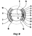
- Fig. 2
- eine längs der Linie II - II in Fig. 1 geschnittene Ansicht der Rasteinrichtung.
- Fig. 3 a
- die Stanzform einer Blattfeder der Rasteinrichtung aus Fig. 1 bzw. Fig. 2, und
- Fig. 3 b
- die Biegeform zu Fig. 3 a.
- Figur 1 zeigt das antriebsseitige Ende eines drehstellbaren Bauelementes mit integrierter Rasteinrichtung. Das Bauelement (1) selbst ist dabei nur andeutungsweise dargestellt.
- In einem Gehäuse (2) befindet sich ein Rotor (3). Der Rotor (3) ist durch eine Stellwelle (4) drehstellbar. Der Rotor (3) und die Stellwelle (4) sind im Gehäuse (2) drehgelagert. Zum Bauelement (1) hin trägt der Rotor (3) ein Kupplungsteil (5) zur Übertragung der Stellbewegung an das Bauelement. Es sind andere Anordnungen der Rasteinrichtung denkbar, bei denen der Rotor (3) das Bauelement (1) direkt stellt. Der Rotor (3) ist im wesentlichen ein Hohlzylinder, er hat einen Zylinderboden (6) und eine gestufte Zylinderwandung (7). Der Rotor (3) ist für sich betrachtet zum Bauelement (1) hin offen; im Beispiel überdeckt das aufgesetzte Kupplungsteil (5) den Rotor (3). Im Innern des Rotors (3) ist eine Blattfeder (8) zwischen ihren Enden an diametral gelegenen Teilen der Zylinderwandung (7) derart eingespannt, daß ihre Form im wesentlichen einem U gleicht. Im Beispiel erstreckt sich der U-Bogen zum Bauelement hin.
- Die Blattfeder (8) hat ein stumpf abgeschnittenes Ende (9) (Fig. 3a), das außenseitig zur Blattfeder (8) hin zurückgebogen in einer Freisparung (10) an der Zylinderwandung (7) anliegt. Das gegenüberliegende Ende (11) der Blattfeder (8) wird von symmetrisch freigeschnittenen Anlageschultern (12) ausgebildet, die sich auf einem geteilten treppenähnlichen Absatz (13) abstützen. Zwischen den Anlageschultern (12) setzt sich die Blattfeder (8) in einer Verlängerung (14) fort. An der Verlängerung (14) ist eine Rastnase (15) ausgebildet. Die Verlängerung ist außenseitig soweit zur Blattfeder (8) hin zurückgebogen, daß im eingebauten Zustand Rastnase (15) und Anlageschultern (12) in der Lage sind radial zur Rotationsachse (16) des Rotors (3) zu federn. Die Verlängerung (14) durchragt die Zylinderwandung (7) durch einen fensterartigen Durchbruch (17) hindurch soweit, daß die Rastnase (15) außerhalb der Zylinderwandung (7) zu liegen kommt.
- Die Blattfeder (8) ist im Bereich ihrer Endabschnitte an Rippen (18) seitengeführt; sie ist dadurch exakt positioniert und kann nicht seitlich ausweichen. Dagegen ist die Verlängerung (14) innerhalb des Durchbruches (17) in Grenzen beweglich; der Durchbruch (17) ist um eine viertel bis halbe Zahnteilung der Rastkontur (19) (s. Fig. 2) breiter als die Breite der Verlängerung. Zwischen ihren Endabschnitten (9,11) liegt die Blattfeder (8) frei. Die Blattfeder (8) ist durch Stoppflächen (23,24) gegen ein Herausfallen aus ihrer Sollposition gesichert.
- Im Gehäuse ist eine Rastkontur (19) eingearbeitet. Sie besteht aus einer nicht näher dargestellten Anreihung von zahnartigen Rastvertiefungen. Im montierten Zustand befindet sich die Rastkontur (19) in Höhe der Rastnase (15), die dabei in die jeweils gegenüberstehende Rastvertiefung eingreift. Die Rastnase (15) federt beim Überstreichen der Rastkontur (19) die Anlageschultern (12) radial nach innen, sodaß an den Anlageschultern ein Abstand zur Innenwand (20) des Rotors (3) entsteht. Wird der Rotor dem Gehäuse (2) entnommen, liegen die Anlageschultern (12) an der Innenwand (20) des Rotors an.
- Während des Drehstellens z.B. entgegen der Uhrzeigerrichtung verwindet sich die weniger präzis geführte Verlängerung (14) zunächst und wird von einer Seitenwand (21) des Durchbruches (17) geschoben. Beim Einrasten der Rastnase in eine Vertiefung der Rastkontur (19) entspannt sich die Verlängerung (14) momentan und schlägt gegen die gegenüberstehende Seitenwand (22). Das Anschlagen ist hörbar. Die akkustische Wahrnehmbarkeit wird durch Schallräume, die beim Einbau der Anordnung in ein Gerät zu schaffen wären, weiter verbessert.
Claims (6)
- Drehstellbares, elektrisches Bauelement, insbesondere Drehschalter oder Drehwiderstand mit einer Rasteinrichtung mit einer Rastnase (15), die anhand einer Blattfeder (8) an einem um seine Rotorachse (16) drehstellbaren Rotor (3) des Bauelementes federnd gehalten ist und mit einer im Bauelement stationär gehaltenen Rastkontur (19), wobei die Rastnase (15) anhand der Blattfeder (8) kraftschlüssig an der Rastkontur (19) anliegt,
dadurch gekennzeichnet,
daß der Rotor (3) ein Hohlkörper ist, mit einer axialen Öffnung und einer radialen Wandung (7), daß die Blattfeder (8) U-förmig gespannt ist und sich mit ihren Enden (9,11) an diametral gelegenen Teilen der Wandung (7) selbsthaltend abstützt, und daß die Rastkontur (19) den Rotor (3) koaxial zur Rotorachse (16) umgibt und die Rastnase (15) in zur Rotorachse (16) radialer Richtung federnd an der Rastkontur (19) anliegt, wobei die Wandung (7) einen Durchbruch (17) aufweist, in welchem die, an einer Verlängerung (14) der Blattfeder (8) ausgebildete Rastnase (15) die Wandung (7) durchragt. - Bauelement nach Anspruch 1,
dadurch gekennzeichnet,
daß zumindest ein Ende der Blattfeder (8) teilweise freigeschnittene Anlageschultern (12) aufweisen die dem exakten Anliegen dienen. - Bauelement nach einem der Ansprüche 1 oder 2,
dadurch gekennzeichnet,
daß die Verlängerung (14) eine geringere Breite aufweist als die Blattfeder (8). - Bauelement nach einem der Ansprüche 1 bis 3,
dadurch gekennzeichnet,
daß die Verlängerung (14) an einer Biegung zur Blattfeder (8) hin zurückgebogen ist, in einer Weise, daß die im zurückgebogenen Bereich der Verlängerung ausgebildete Rastnase (15) im eingebauten Zustand im wesentlichen zur Rotorachse (16) radial nach außen steht. - Bauelement nach Anspruch 4,
dadurch gekennzeichnet,
daß die Rastnase (15) und die Biegeebene der Verlängerung (14) in axialer Richtung beabstandet sind. - Bauelement nach einem der Ansprüche 1 bis 5,
dadurch gekennzeichnet,
daß der Durchbruch (17) um eine viertel bis halbe Zahnteilung der Rastkontur (19) breiter ist als die Breite der Verlängerung (14).
Applications Claiming Priority (2)
| Application Number | Priority Date | Filing Date | Title |
|---|---|---|---|
| DE29501692U DE29501692U1 (de) | 1995-02-03 | 1995-02-03 | Rasteinrichtung für ein drehstellbares Bauelement |
| DE29501692U | 1995-02-03 |
Publications (2)
| Publication Number | Publication Date |
|---|---|
| EP0725410A1 EP0725410A1 (de) | 1996-08-07 |
| EP0725410B1 true EP0725410B1 (de) | 1997-10-08 |
Family
ID=8003345
Family Applications (1)
| Application Number | Title | Priority Date | Filing Date |
|---|---|---|---|
| EP95117658A Expired - Lifetime EP0725410B1 (de) | 1995-02-03 | 1995-11-09 | Drehstellbares Bauelement mit einer Rasteinrichtung |
Country Status (3)
| Country | Link |
|---|---|
| US (1) | US5745025A (de) |
| EP (1) | EP0725410B1 (de) |
| DE (2) | DE29501692U1 (de) |
Families Citing this family (8)
| Publication number | Priority date | Publication date | Assignee | Title |
|---|---|---|---|---|
| DE19629112C2 (de) * | 1996-07-19 | 2002-05-08 | Sidler Gmbh & Co | Drehpotentiometer |
| DE19915990C1 (de) | 1999-04-09 | 2000-05-25 | Preh Elektro Feinmechanik | Bedienteil für Steuerungsfunktionen |
| US6028502A (en) * | 1999-06-02 | 2000-02-22 | Knowles Electronics, Inc. | Potentiometer detent |
| DE10323544B4 (de) * | 2003-05-24 | 2005-10-27 | Preh Gmbh | Rasteinrichtung für ein dreheinstellbares, elektrisches Bauelement |
| US7404344B2 (en) | 2003-05-24 | 2008-07-29 | Preh Gmbh | Ratchet device for an electrical component which may be adjusted by rotation |
| JP5275183B2 (ja) * | 2009-09-14 | 2013-08-28 | 日本トムソン株式会社 | フォロア軸受の潤滑装置 |
| US9859879B2 (en) | 2015-09-11 | 2018-01-02 | Knowles Electronics, Llc | Method and apparatus to clip incoming signals in opposing directions when in an off state |
| CN113363028B (zh) * | 2021-06-30 | 2023-02-03 | 安徽功率电气有限公司 | 一种方便使用的电阻器 |
Family Cites Families (16)
| Publication number | Priority date | Publication date | Assignee | Title |
|---|---|---|---|---|
| US2396970A (en) * | 1944-02-02 | 1946-03-19 | Mallory & Co Inc P R | Variable resistance |
| FR994452A (fr) * | 1949-07-01 | 1951-11-16 | Dispositif destiné à assurer à un contacteur électrique des positions d'arrêt à espacement angulaire déterminé | |
| US2632830A (en) * | 1950-12-27 | 1953-03-24 | Mallory & Co Inc P R | Indexed control |
| US2631212A (en) * | 1952-07-24 | 1953-03-10 | Dejur Amsco Corp | Potentiometer tandem assembly |
| US2980770A (en) * | 1958-12-18 | 1961-04-18 | Daven Company | Miniature switch |
| US3579169A (en) * | 1969-02-05 | 1971-05-18 | Allen Bradley Co | Variable resistor for dual operation |
| US3643044A (en) * | 1971-02-23 | 1972-02-15 | Joseph Pollok Corp | Ratchet apparatus and switch construction |
| US3973094A (en) * | 1975-04-28 | 1976-08-03 | Allen-Bradley Company | Two-stage snap-action switch |
| US4105988A (en) * | 1976-12-22 | 1978-08-08 | Cts Corporation | Tandem electrical control |
| DE2735352C2 (de) * | 1977-08-05 | 1983-11-10 | Preh, Elektrofeinmechanische Werke, Jakob Preh, Nachf. Gmbh & Co, 8740 Bad Neustadt | In Modulbauweise hergestellter einstellbarer Widerstand |
| DE2824584C2 (de) * | 1978-06-05 | 1986-02-06 | Ebe Elektro-Bau-Elemente Gmbh, 7022 Leinfelden-Echterdingen | Mehrfach-Stufendrehschalter |
| DE3139094A1 (de) * | 1980-11-12 | 1982-06-24 | Alps Electric Co., Ltd., Tokyo | Anzeigevorrichtung fuer einen veraenderbaren widerstand |
| JPH0532967Y2 (de) * | 1985-11-06 | 1993-08-23 | ||
| DE4035011C2 (de) * | 1990-11-03 | 1994-10-20 | Ebe Elektro Bau Elemente Gmbh | Rastwerk, insbesondere für Stufenschalter |
| US5187464A (en) * | 1992-05-11 | 1993-02-16 | Ford Motor Company | Extended life potentiometric position transducer |
| FR2694126B1 (fr) * | 1992-07-27 | 1994-10-07 | Jaeger | Commutateur électrique, notamment pour véhicules automobiles, comprenant des moyens d'indexage angulaire perfectionnés. |
-
1995
- 1995-02-03 DE DE29501692U patent/DE29501692U1/de not_active Expired - Lifetime
- 1995-11-09 DE DE59500773T patent/DE59500773D1/de not_active Expired - Fee Related
- 1995-11-09 EP EP95117658A patent/EP0725410B1/de not_active Expired - Lifetime
-
1996
- 1996-01-26 US US08/592,683 patent/US5745025A/en not_active Expired - Fee Related
Also Published As
| Publication number | Publication date |
|---|---|
| US5745025A (en) | 1998-04-28 |
| EP0725410A1 (de) | 1996-08-07 |
| DE29501692U1 (de) | 1995-04-06 |
| DE59500773D1 (de) | 1997-11-13 |
Similar Documents
| Publication | Publication Date | Title |
|---|---|---|
| EP1627399B1 (de) | Rasteinrichtung für ein dreheinstellbares, elektrisches bauelement | |
| EP1024267A2 (de) | Drosselklappendrehwinkelsensor | |
| EP2329508B1 (de) | Handantrieb | |
| WO2009143946A1 (de) | Drehrichtungsanzeiger | |
| EP2261445A2 (de) | Schloss, insbesondere Türschloss, mit verbesserter Schließmechanik | |
| DE102009047715A1 (de) | Einschienenschalteinrichtung | |
| EP0960426A1 (de) | Stellungsmeldeanordnung | |
| EP0725410A1 (de) | Rasteinrichtung für ein drehstellbares Bauelement | |
| EP0367781B1 (de) | Drehwinkel-potentiometer | |
| DE4015525C2 (de) | Visuelle Anzeigevorrichtung | |
| DE10126076B4 (de) | Impulsgeber | |
| DE4035011C2 (de) | Rastwerk, insbesondere für Stufenschalter | |
| EP2297760B1 (de) | Wippschalter | |
| DE2414203A1 (de) | Netzstecker fuer zwei verschiedene anschlusskontakte | |
| DE4436724C2 (de) | Elektronischer Positionsgeber | |
| DE10111400B4 (de) | Stellantrieb für Heizungs-, Lüftungs- oder Klimaklappen in einem Kraftfahrzeug | |
| EP0314150B1 (de) | Drehpotentiometer | |
| DE9407625U1 (de) | Drehschalter | |
| DE3039696C2 (de) | Meßumformer für einen Stellantrieb | |
| EP0647954B1 (de) | Drehantrieb | |
| DE3319404C2 (de) | Impulsgenerator | |
| DE10318358A1 (de) | Bedienelement | |
| EP3218913B1 (de) | Vorrichtung zur betätigung eines drehschalters | |
| DE3930821C2 (de) | ||
| DE10244182B3 (de) | Elektrisches Schaltgerät mit Schaltstellungsanzeige |
Legal Events
| Date | Code | Title | Description |
|---|---|---|---|
| PUAI | Public reference made under article 153(3) epc to a published international application that has entered the european phase |
Free format text: ORIGINAL CODE: 0009012 |
|
| AK | Designated contracting states |
Kind code of ref document: A1 Designated state(s): DE FR GB IT |
|
| 17P | Request for examination filed |
Effective date: 19960831 |
|
| GRAG | Despatch of communication of intention to grant |
Free format text: ORIGINAL CODE: EPIDOS AGRA |
|
| GRAH | Despatch of communication of intention to grant a patent |
Free format text: ORIGINAL CODE: EPIDOS IGRA |
|
| 17Q | First examination report despatched |
Effective date: 19970324 |
|
| GRAH | Despatch of communication of intention to grant a patent |
Free format text: ORIGINAL CODE: EPIDOS IGRA |
|
| GRAA | (expected) grant |
Free format text: ORIGINAL CODE: 0009210 |
|
| AK | Designated contracting states |
Kind code of ref document: B1 Designated state(s): DE FR GB IT |
|
| ITF | It: translation for a ep patent filed | ||
| ET | Fr: translation filed | ||
| GBT | Gb: translation of ep patent filed (gb section 77(6)(a)/1977) |
Effective date: 19971010 |
|
| REF | Corresponds to: |
Ref document number: 59500773 Country of ref document: DE Date of ref document: 19971113 |
|
| PLBE | No opposition filed within time limit |
Free format text: ORIGINAL CODE: 0009261 |
|
| STAA | Information on the status of an ep patent application or granted ep patent |
Free format text: STATUS: NO OPPOSITION FILED WITHIN TIME LIMIT |
|
| 26N | No opposition filed | ||
| PGFP | Annual fee paid to national office [announced via postgrant information from national office to epo] |
Ref country code: GB Payment date: 20001013 Year of fee payment: 6 |
|
| PGFP | Annual fee paid to national office [announced via postgrant information from national office to epo] |
Ref country code: FR Payment date: 20001101 Year of fee payment: 6 |
|
| PGFP | Annual fee paid to national office [announced via postgrant information from national office to epo] |
Ref country code: DE Payment date: 20001102 Year of fee payment: 6 |
|
| PG25 | Lapsed in a contracting state [announced via postgrant information from national office to epo] |
Ref country code: GB Free format text: LAPSE BECAUSE OF NON-PAYMENT OF DUE FEES Effective date: 20011109 |
|
| REG | Reference to a national code |
Ref country code: GB Ref legal event code: IF02 |
|
| GBPC | Gb: european patent ceased through non-payment of renewal fee |
Effective date: 20011109 |
|
| PG25 | Lapsed in a contracting state [announced via postgrant information from national office to epo] |
Ref country code: DE Free format text: LAPSE BECAUSE OF NON-PAYMENT OF DUE FEES Effective date: 20020702 |
|
| PG25 | Lapsed in a contracting state [announced via postgrant information from national office to epo] |
Ref country code: FR Free format text: LAPSE BECAUSE OF NON-PAYMENT OF DUE FEES Effective date: 20020730 |
|
| REG | Reference to a national code |
Ref country code: FR Ref legal event code: ST |
|
| REG | Reference to a national code |
Ref country code: FR Ref legal event code: ST |
|
| PG25 | Lapsed in a contracting state [announced via postgrant information from national office to epo] |
Ref country code: IT Free format text: LAPSE BECAUSE OF NON-PAYMENT OF DUE FEES Effective date: 20051109 |