EP0723522B1 - Vorrichtung zum schwebendführen einer laufenden bahn - Google Patents
Vorrichtung zum schwebendführen einer laufenden bahn Download PDFInfo
- Publication number
- EP0723522B1 EP0723522B1 EP94928287A EP94928287A EP0723522B1 EP 0723522 B1 EP0723522 B1 EP 0723522B1 EP 94928287 A EP94928287 A EP 94928287A EP 94928287 A EP94928287 A EP 94928287A EP 0723522 B1 EP0723522 B1 EP 0723522B1
- Authority
- EP
- European Patent Office
- Prior art keywords
- air
- accordance
- web
- duct
- wall
- Prior art date
- Legal status (The legal status is an assumption and is not a legal conclusion. Google has not performed a legal analysis and makes no representation as to the accuracy of the status listed.)
- Expired - Lifetime
Links
Images

Classifications
-
- B—PERFORMING OPERATIONS; TRANSPORTING
- B65—CONVEYING; PACKING; STORING; HANDLING THIN OR FILAMENTARY MATERIAL
- B65H—HANDLING THIN OR FILAMENTARY MATERIAL, e.g. SHEETS, WEBS, CABLES
- B65H23/00—Registering, tensioning, smoothing or guiding webs
- B65H23/04—Registering, tensioning, smoothing or guiding webs longitudinally
- B65H23/32—Arrangements for turning or reversing webs
-
- B—PERFORMING OPERATIONS; TRANSPORTING
- B65—CONVEYING; PACKING; STORING; HANDLING THIN OR FILAMENTARY MATERIAL
- B65H—HANDLING THIN OR FILAMENTARY MATERIAL, e.g. SHEETS, WEBS, CABLES
- B65H23/00—Registering, tensioning, smoothing or guiding webs
- B65H23/04—Registering, tensioning, smoothing or guiding webs longitudinally
- B65H23/24—Registering, tensioning, smoothing or guiding webs longitudinally by fluid action, e.g. to retard the running web
-
- D—TEXTILES; PAPER
- D21—PAPER-MAKING; PRODUCTION OF CELLULOSE
- D21F—PAPER-MAKING MACHINES; METHODS OF PRODUCING PAPER THEREON
- D21F5/00—Dryer section of machines for making continuous webs of paper
- D21F5/18—Drying webs by hot air
- D21F5/185—Supporting webs in hot air dryers
- D21F5/187—Supporting webs in hot air dryers by air jets
- D21F5/188—Blowing devices
-
- F—MECHANICAL ENGINEERING; LIGHTING; HEATING; WEAPONS; BLASTING
- F26—DRYING
- F26B—DRYING SOLID MATERIALS OR OBJECTS BY REMOVING LIQUID THEREFROM
- F26B13/00—Machines and apparatus for drying fabrics, fibres, yarns, or other materials in long lengths, with progressive movement
- F26B13/10—Arrangements for feeding, heating or supporting materials; Controlling movement, tension or position of materials
- F26B13/101—Supporting materials without tension, e.g. on or between foraminous belts
- F26B13/104—Supporting materials without tension, e.g. on or between foraminous belts supported by fluid jets only; Fluid blowing arrangements for flotation dryers, e.g. coanda nozzles
-
- B—PERFORMING OPERATIONS; TRANSPORTING
- B65—CONVEYING; PACKING; STORING; HANDLING THIN OR FILAMENTARY MATERIAL
- B65H—HANDLING THIN OR FILAMENTARY MATERIAL, e.g. SHEETS, WEBS, CABLES
- B65H2406/00—Means using fluid
- B65H2406/10—Means using fluid made only for exhausting gaseous medium
- B65H2406/11—Means using fluid made only for exhausting gaseous medium producing fluidised bed
- B65H2406/111—Means using fluid made only for exhausting gaseous medium producing fluidised bed for handling material along a curved path, e.g. fluidised turning bar
-
- B—PERFORMING OPERATIONS; TRANSPORTING
- B65—CONVEYING; PACKING; STORING; HANDLING THIN OR FILAMENTARY MATERIAL
- B65H—HANDLING THIN OR FILAMENTARY MATERIAL, e.g. SHEETS, WEBS, CABLES
- B65H2406/00—Means using fluid
- B65H2406/10—Means using fluid made only for exhausting gaseous medium
- B65H2406/14—Means using fluid made only for exhausting gaseous medium with selectively operated air supply openings
Definitions
- the invention relates to a device of the type corresponding to the preamble of claim 1.
- the web When producing or processing a web from a sensitive material, such as paper or the like, it has proven advantageous to avoid damage to the web or its surface, the web for the duration of the drying process of the web material or its surface coating keep floating. Arrangements are usually used for this purpose, in which air supplied by a blower is blown out via nozzles from one or both sides of the web, so that the web is carried by the air cushion thus produced. The air thus flowing around the web accelerates the drying process, which is usually additionally supported by means of heating devices that extend across the web width.
- the drying rate of a sheet of the web has an upper limit, for example due to the maximum thermal load capacity of the web material, which leads to the sheet being made for a minimum Time must be in a floating state, the webs must be carried floating over ever greater lengths. Because of the relatively low strength, especially of moist paper webs, the maximum achievable distance between two consecutive floating end guides is limited, this development goes hand in hand with an ever increasing number of support points required for guiding a web, which on the one hand the amount of air required for web guiding and thus the required energy requirement, and on the other hand the Space requirement of a drying device increased. The increased space requirement is usually taken into account by the fact that the paper web is deflected several times, whereby the base area of the device required for this is reduced with the same length of the freely floating web section.
- the devices usually comprise so-called nozzle boxes, from which the air exits in the direction of the web. Often the nozzles have a slot shape (as for example in a device according to DE-PS 31 30 450).
- the nozzle boxes are arranged at a distance from one another in the direction of travel of the web, the spaces serving as discharge paths for the air, which then, as in the device known from GB-PS 13 07 695, escapes essentially over the areas of the two web edges .
- the free escape of air over the web edges leads on the one hand to a large consumption of compressed air and thus to a high energy requirement, on the other hand to an unstable run and to an unsatisfactory guidance of the web.
- slot-shaped air outlet nozzles are provided in the area of the two web edges, which inhibit the air outlet flows on the web edge side and thus generate backpressures in the area of the web edges, which exert a positive influence on the guidance of the web.
- a disadvantage of the web deflection device described in DE-OS 29 32 794 is that the energy requirement increases again through the additional nozzles through which further compressed air has to be blown in.
- DE-OS 29 32 794 A further development of DE-OS 29 32 794 is the device according to DE-PS 31 04 656, in which good properties with regard to the guidance and the stable running of the web are to be achieved by a special choice of the nozzle cross-sections and their geometric arrangement.
- the expected energy consumption is still quite high.
- a device for drying and / or holding a moving web which has a series of parallel air bars, in each of which a few elongated Coanda nozzles extending in the longitudinal direction of the air bars are arranged. Compressed air flows through the Coanda nozzles from an air chamber provided in the device in the form of flows, which serve for contactless support of the material web guided over the device.
- the first air dams that limit the lateral air flow are arranged on the top of the device, away from the latter vertically upward-extending, second air dams enclosing the web are provided.
- the disadvantage of this device is that the distance between the second air dams and for an effective reduction of the air requirement and thus the energy consumption the material web must be as small as possible, but this is only possible with a very exact guidance of the material web, since this can otherwise be damaged by possible contact with the air dams.
- FIG. 1 Another embodiment of a web guiding device is known from DE 36 26 016 A1.
- an improved guiding effect on the web is achieved in that air channels are provided as nozzle boxes which are arranged transversely to the running direction of the web and comprise lateral channel walls which form an acute angle to one another, a row of nozzles being incorporated in each channel wall in such a way that each nozzle is opposite a guiding surface for the outflowing air formed by the other duct wall.
- the Coanda effect an air flow that is favorable for stabilizing the web is generated.
- the disadvantage of this web guiding device is that the web tends to bulge into the air duct along an isobar, since, due to the Bernoulli law, there is a reduced pressure for fluid media above each air duct.
- the object of the invention is to improve the functionality of a generic device.
- inlet openings arranged according to the invention near the longitudinal ends of the wall surfaces facing the material web, at least some of the flowable medium sucked in by the ejector effect is sucked out of a region of increased pressure, whereby the efficiency and the web guiding behavior of the device are improved.
- the increased pressure of the flowable medium in the vicinity of the band edges and the flow component thereby directed outwards can additionally be exploited in that at least one flow guide plate partially surrounding the inlet openings is provided. Tests have shown that energy savings of up to 25% can be achieved with a device according to the invention designed in this way.
- a configuration of the air duct is particularly advantageous in which duct walls are provided on both sides of a transverse plane lying in the longitudinal direction of the air duct, which is perpendicular to the tangential plane formed by the line of penetration formed by the web (claim 3).
- the nozzle arrangement consists of a series of individual outflow openings which are arranged in one channel wall opposite flow guide surfaces formed by the other channel wall (claim 4). Due to the fact that in such an embodiment the channel walls are designed as flow guiding surfaces in the areas of the impinging air flows, very favorable flow conditions can be achieved. In particular, it is possible to generate particularly low-swirl air currents that follow the surface of the respective duct wall according to the so-called Coanda effect.
- a further equalization of the air flows can be generated according to claim 5 in that the outflow openings are designed as holes which are surrounded by concentric flow guide edges projecting into the air duct.
- two duct walls provided with an outflow opening and arranged directly opposite one another form an air duct and each of these duct walls at least partially a guide surface for from the outlets of the other duct wall emerging flows of the fluid medium forms.
- the tendency to form strong turbulence is reduced if the outflow openings of the one channel wall are laterally offset from the outflow openings of the other channel wall (claim 7).
- the device comprises a plurality of air ducts, it is furthermore particularly advantageous to reduce the tendency for harmful vortex formation if the outlet openings provided in one duct wall of one air duct are arranged opposite the outlet openings provided in the other duct wall of an adjacent air duct.
- the device according to the invention is also particularly suitable for achieving low-swirling air flows if it is designed according to claims 9 and 10, since this enables a uniform, edge-free guidance of the air flows out of the air ducts.
- An embodiment of the air channels according to claims 11 and 12 is particularly suitable for utilizing the ejector effect of the inflowing medium. In order to achieve the maximum ejector effect, it is then advantageous to provide individual holes that interrupt the lower boundary line of the air channel as inflow openings.
- inlet slot nozzles which extend over a substantial length of the air duct along the lower boundary line instead of the individual inflow openings.
- This configuration of the Inflow openings are particularly recommended when both duct walls consist of two separate components, which are then to be arranged such that they are spaced apart in the lower region of the air duct in accordance with the required inlet slot nozzle width.
- This embodiment has the advantage that no further processing steps are required to create the inflow opening.
- a device provided for deflecting a web it is advantageous to provide a plurality of air channels, the transverse planes of which intersect in a common line, so that the envelope of the device is curved in accordance with the deflecting direction (claim 16).
- an embodiment is advantageous in which, according to claim 17, the angular distance between adjacent transverse planes is approximately constant. The formation of additional eddies can be counteracted by the wall surfaces of the device being curved, advantageously with constant radii of curvature (claim 19).
- stabilization nozzles are provided in the wall parts of the device arranged at the beginning and at the end of the deflection area, which communicate with the pressure chamber. Such stabilizing nozzles help to avoid harmful contact between the web and the device even when the web flutters slightly.
- the device can also be used for suspension or deflection of narrower webs without a large part of the pressurized flow medium unused in the environment with the resulting disadvantages. Furthermore, this configuration of the device according to the invention makes it possible to increase the pressure of the sections which act on the web edges with the flowable medium relative to the other sections of the pressure chamber, as a result of which the lateral guiding properties of the device are further improved.
- the means for separate control of the pressure from the individual sections upstream, continuously controllable plate valves (claim 22).
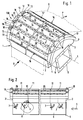
- the information refers to the upright operating position of the device shown in FIGS. 1 and 2, the information "front”, “left” or “right” “refer to the view in FIG. 2.
- the device designated 100 as a whole in the drawing serves for the floatingly guided deflection of a paper web B, which executes a movement in the direction of the arrow P.
- a flat upper side 12 it is also within the scope of the invention to equip the device with a flat upper side 12 and to use it for guiding a linear path.
- the facilities for driving the train are in not shown in the drawing and can be formed in a known manner.
- the device 100 comprises a substantially closed housing 1, which has the shape of a cylinder segment, the angular extent of the cylindrical surface depending on the required path deflection angle - in the exemplary embodiment shown in the drawing, approximately 120 °.
- the longitudinal boundaries of the housing form two parallel longitudinal walls 2, 2 '.
- the housing is delimited by means of side segments 3, 3 ′ which are arranged in a segment of a circle and which have straight lower edges which run parallel to one another.
- the underside of the housing forms a flat wall 4, into which air inlet openings 5 which are symmetrical to the longitudinal axis L of the device are incorporated.
- an air supply duct 6, which extends over the entire length of the device 100 and in whose interior the air inlet openings 5 open.
- Valve flaps 8 which can be actuated from the outside by means of handles 7 are provided in the air supply duct 6, by means of which the cross sections of the air inlet openings 5 can be changed by pivoting in the direction of the arrow K in FIG. 2.
- a flange 9 is arranged, which serves to connect an air supply hose (not shown in the drawing), which usually connects the device to a blower.
- the inner volume of the housing 1 serving as the pressure chamber 10 is sectioned by means of intermediate walls 11 arranged parallel to the side parts 3, 3 '.
- Each of the air inlet openings 5 is currently communicating with a section of the pressure chamber 10, so that a pressure profile extending across the width of the web B can be adjusted by means of the valve flaps 8.
- this configuration makes it possible to apply an increased air pressure to the web edges, which results in a better lateral pressure Guidance of the web is achieved.
- the substantially constant radius of curvature of the upper side 12 of the housing 1 comprises a plurality - in the exemplary embodiment shown five - extending across the entire width of the device, mutually parallel air channels 13, the design of which will be explained in more detail below.
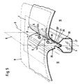
- wall surfaces 14 forming the upper side 12 are provided, which are curved in accordance with the radius of curvature of the device.
- arrangements of stabilizing nozzles are provided in the outer wall surfaces 15, 15 ′, which extend over the entire width of the web B and communicate with the pressure chamber 10 and through which air for additional support of the web B, for example is blown off radially outwards.
- Suction chambers 17 are provided on both end faces of the device, the function of which will be explained in more detail below.
- the suction chambers 17 comprise inlet openings 19 surrounded by flow guide plates 18, which are arranged at the ends of the wall surfaces 14.
- An air duct 13 comprises two lateral, opposite duct walls 20, 20 ', which are convexly curved to the path and each merge into a wall surface 14 towards the outside.
- the channel walls 20, 20 ' are pulled down just so far in the direction of the interior of the housing 1 that they meet at an acute angle ⁇ , so that the air channel 13 has a straight, linear shape under delimitation 21.
- the curvatures of the channel walls are selected so that the air channel 13 has a V-shaped cross section, the channel walls 20, 20 'being symmetrical a transverse plane Q lying in the longitudinal direction of the air duct, which is perpendicular to the tangential plane T applied to its penetration line D formed with the path B, is arranged.
- an air channel 13 Provided in the channel walls 20, 20 'of an air channel 13 is a row of nozzles 22, 22' which extends over the web width and which consists of individual, hole-shaped outflow openings 23 corresponding to the pressure chamber 10.
- the outflow openings 23 are provided with flow guiding edges 24 which protrude into the air duct 13 and which surround the outflow openings 23 concentrically to reduce the eddy formation of outflowing air.
- the flow guide edges 24 can be produced in a simple manner in that the edges of the holes 23 are flanged into the air duct 13.
- the outflow openings 23 of the nozzle rows 22, 22 ' are arranged laterally offset from one another so that the air flow emerging from an outflow opening 23 hits the opposite channel wall 20, 20', which forms a guide surface 25, 25 'for the air flow in this area.
- an air duct 13 there is a row of additional inflow openings 26 which extend across the width of the web and are fluidly connected to a suction duct 27 which is arranged inside the housing 1 and extends along the air duct.
- the suction duct is formed by a wall 28 which is drawn around the lower boundary 21 of an air duct 13 in the interior of the housing 1 and which is connected gas-tightly below the inflow openings 23 to the duct walls 20, 20 '.
- the suction channel 27 pierces the side parts 3, 3 'and opens into the suction chamber 17 arranged as described.
- the course of the air flow of the device 100 in operation is to be clarified by the double arrows shown in FIGS. 1 to 5 and denoted by S.
- the via the air supply channel 6 by means of a Air supplied to the blower (not shown) passes through the air inlet openings 5 into the various sections of the pressure chambers 10, controlled in terms of quantity by the valve flaps 8.
- the air coming from the air duct 13 to the wall surfaces 14 on the principle of the Coanda effect is preferably discharged via the longitudinal ends of the wall surfaces 14 and finally reaches the area of the upstream flow guide plates 18, where it preferably passes through the corresponding inlet opening 19 and the suction duct 27 the suction chamber 17 is supplied to the inflow openings 26.
Landscapes
- Engineering & Computer Science (AREA)
- Textile Engineering (AREA)
- Mechanical Engineering (AREA)
- General Engineering & Computer Science (AREA)
- Advancing Webs (AREA)
- Control Of Vehicles With Linear Motors And Vehicles That Are Magnetically Levitated (AREA)
- Train Traffic Observation, Control, And Security (AREA)
- Control Of Multiple Motors (AREA)
Applications Claiming Priority (3)
| Application Number | Priority Date | Filing Date | Title |
|---|---|---|---|
| DE4334473A DE4334473C2 (de) | 1993-10-11 | 1993-10-11 | Vorrichtung zum Schwebendführen einer laufenden Bahn |
| DE4334473 | 1993-10-11 | ||
| PCT/DE1994/001166 WO1995010473A1 (de) | 1993-10-11 | 1994-10-06 | Vorrichtung zum schwebendführen einer laufenden bahn |
Publications (2)
| Publication Number | Publication Date |
|---|---|
| EP0723522A1 EP0723522A1 (de) | 1996-07-31 |
| EP0723522B1 true EP0723522B1 (de) | 1997-12-17 |
Family
ID=6499791
Family Applications (1)
| Application Number | Title | Priority Date | Filing Date |
|---|---|---|---|
| EP94928287A Expired - Lifetime EP0723522B1 (de) | 1993-10-11 | 1994-10-06 | Vorrichtung zum schwebendführen einer laufenden bahn |
Country Status (6)
| Country | Link |
|---|---|
| US (1) | US6502735B1 (fi) |
| EP (1) | EP0723522B1 (fi) |
| AT (1) | ATE161239T1 (fi) |
| DE (2) | DE4334473C2 (fi) |
| FI (1) | FI117333B (fi) |
| WO (1) | WO1995010473A1 (fi) |
Families Citing this family (11)
| Publication number | Priority date | Publication date | Assignee | Title |
|---|---|---|---|---|
| EP0965546A1 (en) * | 1998-06-17 | 1999-12-22 | E.I. Du Pont De Nemours And Company | Web transport system |
| WO2000039011A2 (de) * | 1998-12-23 | 2000-07-06 | Bachofen + Meier Ag Maschinenfabrik | Vorrichtung zum berührungslosen führen oder behandeln einer laufenden materialbahn, insbesondere papier- oder kartonbahn, metall- oder kunststoffolie |
| DE19915120A1 (de) * | 1999-04-01 | 2000-10-05 | Krieger Gmbh & Co Kg | Vorrichtung zum berührungslosen Umlenken einer bewegten Bahn |
| DE10317372A1 (de) * | 2003-04-15 | 2004-11-04 | Voith Paper Patent Gmbh | Entwässerungseinrichtung |
| DE10335580A1 (de) * | 2003-07-31 | 2005-02-24 | Voith Paper Patent Gmbh | Vorrichtung zur Führung einer laufenden Faserstoffbahn |
| DE102007058405B4 (de) * | 2007-11-02 | 2010-03-25 | Gerhard Bach | Umlenkvorrichtung zum Umlenken von flexiblem Flachmaterial |
| DE102008005659B4 (de) * | 2008-01-23 | 2010-12-09 | Gerhard Bach | Umlenkelement für flexibles Flachmaterial und Verfahren zu seinem Betreiben |
| DE102009060276A1 (de) * | 2009-12-23 | 2011-06-30 | Eastman Kodak Co., N.Y. | Vorrichtung zum Wenden von bahnförmigen Substraten |
| CN104030073B (zh) * | 2014-06-26 | 2016-06-08 | 湖南正大轻科机械有限公司 | 一种空气转向器 |
| DE102015106465B4 (de) | 2015-04-27 | 2017-01-12 | Technische Universität Dresden | Druckprüfvorrichtung und Druckprüfverfahren für dünnwandige Materialien |
| US11549753B2 (en) * | 2017-01-24 | 2023-01-10 | Illinois Tool Works Inc. | Laminar flow shrink oven |
Family Cites Families (27)
| Publication number | Priority date | Publication date | Assignee | Title |
|---|---|---|---|---|
| DE356034C (de) | 1918-05-21 | 1922-07-11 | Fried Krupp Akt Ges | Drehscheibe fuer Eisenbahngeschuetze |
| FR1149169A (fr) * | 1955-03-14 | 1957-12-20 | Vits Elektro G M B H | Installation de tuyères de soufflerie pour sécheuses pour produits sous forme de bande |
| GB876221A (en) * | 1957-01-02 | 1961-08-30 | Emi Ltd | Improvements in or relating to web transport apparatus |
| US3184131A (en) * | 1962-08-20 | 1965-05-18 | Potter Instrument Co Inc | Continuous tape system |
| BE645430A (fi) * | 1963-03-19 | |||
| US3324570A (en) * | 1965-02-25 | 1967-06-13 | Proctor And Schwartz Inc | Float dryer |
| GB1307695A (en) * | 1970-08-19 | 1973-02-21 | Ilford Ltd | Air flotation turner bars |
| FR2274527A1 (fr) * | 1974-06-11 | 1976-01-09 | Bertin & Cie | Dispositif transporteur de lettres, plis postaux ou autres objets minces |
| US3984039A (en) * | 1974-12-16 | 1976-10-05 | International Business Machines Corporation | Precision-surface with dynamically-stiff air film provided by deep pools |
| JPS6033740B2 (ja) * | 1975-10-06 | 1985-08-05 | コニカ株式会社 | 可撓性帯状物の搬送装置 |
| NO141469L (fi) * | 1975-12-09 | |||
| CH599893A5 (fi) * | 1976-12-17 | 1978-06-15 | Bachofen & Meier Maschf | |
| DE2961177D1 (en) | 1978-01-27 | 1982-01-14 | Spooner Edmeston Eng | Float treatment apparatus |
| US4197972A (en) * | 1978-08-28 | 1980-04-15 | W. R. Grace & Co. | Contactless turning guide having air slots longitudinally along running web edges |
| DE2935866A1 (de) * | 1978-09-11 | 1980-03-20 | Valmet Oy | Bahntrockner nach dem lufttrageprinzip |
| US4288015A (en) * | 1980-02-11 | 1981-09-08 | W. R. Grace & Co. | Contactless web turning guide |
| DE3130450C2 (de) * | 1981-07-23 | 1985-06-13 | Langbein & Engelbracht GmbH & Co, KG Bau lufttechnischer Anlagen, 4630 Bochum | Vorrichtung zum Trocknen von bahn- oder bogenförmigem Gut |
| GB2126974B (en) * | 1982-09-07 | 1985-09-11 | Grace W R & Co | Device for supporting a web on a bed of air |
| GB2146303B (en) * | 1983-08-20 | 1987-01-14 | Spooner Ind Ltd | Device for supporting web on a bed of air |
| US4605146A (en) * | 1985-02-15 | 1986-08-12 | E. I. Du Pont De Nemours And Company | Hydrostatic film support |
| FI73478C (fi) | 1985-09-24 | 1987-10-09 | Valmet Oy | Anordning foer kontaktloes stabilisering, uppbaering och/eller torkning av en roerlig bana. |
| DE3626016A1 (de) * | 1986-07-31 | 1988-02-04 | Kurt Krieger | Vorrichtung zum beaufschlagen von materialbahnen mit stroemungsmedium |
| JPH02300051A (ja) * | 1989-05-15 | 1990-12-12 | Fuji Photo Film Co Ltd | ウエブの空気浮上搬送・乾燥装置 |
| JP2770518B2 (ja) * | 1990-01-10 | 1998-07-02 | 石川島播磨重工業株式会社 | 帯板浮揚支持装置 |
| GB2245256A (en) * | 1990-06-02 | 1992-01-02 | Spooner Ind Ltd | Pneumatic web guides |
| FI92421B (fi) | 1992-03-19 | 1994-07-29 | Valmet Paper Machinery Inc | Menetelmä ainesratojen ilmakuivatuksessa, ilmakuivattimen suutin-puhalluslaatikko ja sellukuivatin |
| US5317817A (en) * | 1992-04-30 | 1994-06-07 | W. R. Grace & Co.-Conn. | Trailing sheet assembly for an air turn |
-
1993
- 1993-10-11 DE DE4334473A patent/DE4334473C2/de not_active Expired - Fee Related
-
1994
- 1994-10-06 US US08/624,610 patent/US6502735B1/en not_active Expired - Fee Related
- 1994-10-06 DE DE59404839T patent/DE59404839D1/de not_active Expired - Lifetime
- 1994-10-06 AT AT94928287T patent/ATE161239T1/de not_active IP Right Cessation
- 1994-10-06 WO PCT/DE1994/001166 patent/WO1995010473A1/de active IP Right Grant
- 1994-10-06 EP EP94928287A patent/EP0723522B1/de not_active Expired - Lifetime
-
1996
- 1996-04-10 FI FI961572A patent/FI117333B/fi not_active IP Right Cessation
Also Published As
| Publication number | Publication date |
|---|---|
| US6502735B1 (en) | 2003-01-07 |
| FI961572A (fi) | 1996-04-10 |
| DE4334473A1 (de) | 1995-04-13 |
| DE4334473C2 (de) | 1997-07-03 |
| FI961572A0 (fi) | 1996-04-10 |
| ATE161239T1 (de) | 1998-01-15 |
| DE59404839D1 (de) | 1998-01-29 |
| FI117333B (fi) | 2006-09-15 |
| WO1995010473A1 (de) | 1995-04-20 |
| EP0723522A1 (de) | 1996-07-31 |
Similar Documents
| Publication | Publication Date | Title |
|---|---|---|
| DE2556442C2 (de) | Vorrichtung zur schwebend Führung von Warenbahnen | |
| DE69219707T2 (de) | Unterdruckdüsenanordnung zur Behandlung von Bahnen | |
| EP0749398B1 (de) | Vorrichtung zum schwebenden führen von bogen oder bahnen | |
| EP0482500B1 (de) | Leitvorrichtung zum Führen, Aus- und/oder Umlenken einer Materialbahn | |
| DE69330413T2 (de) | Verfahren zum Lufttrocknen von freigeführten Materialbahnen and Lufttrockner zur Durchführung des Verfahrens | |
| DE2253170C2 (de) | Verfahren und Vorrichtung zum Behandeln einer frei schwebend geführten Materialbahn | |
| EP1792860B1 (de) | Unterdruck-Bandfördervorrichtung zum Führen einer laufenden Bahn | |
| EP0427015A2 (de) | Vorrichtung zum schwebenden Führen von zu fördernden Materialbahnen oder Materialablagebogen | |
| DE4406848C2 (de) | Blaskasten zum schwebenden Führen von Bogen oder Bahnen | |
| CH637089A5 (de) | Blaskasten zum schwebenden fuehren und/oder foerdern von bahnen oder bogen. | |
| EP0723522B1 (de) | Vorrichtung zum schwebendführen einer laufenden bahn | |
| DE1474239C3 (de) | Verfahren und Einrichtung zur Stabilisierung der Lage unter Wirkung eines Blasmittels schwebend geführter Warenbahnen | |
| DE2836103C2 (de) | Luftdüse für einen Düsentrockner | |
| DE2160131B2 (de) | Vorrichtung zum berUhrungslosen Tragen und Trocknen von laufenden Materialbahnen | |
| DE19807511C2 (de) | Trocken- und/oder Fixiervorrichtung | |
| EP0864518B1 (de) | Schwebedüsenfeld zur schwebenden Führung von Warenbahnen | |
| EP0298299B1 (de) | Vorrichtung zum berührungslosen Führen von Materialbahnen | |
| EP0277159B1 (de) | Vorrichtung zum beaufschlagen von materialbahnen mit strömungsmedium | |
| DE3716468C2 (fi) | ||
| DE3942029B4 (de) | Vorrichtung zum Tragen, Umlenken und Spreizen einer Bahn | |
| EP0723523B1 (de) | Verfahren und vorrichtung zur stabilisierung einer laufenden bahn | |
| DE3130450C2 (de) | Vorrichtung zum Trocknen von bahn- oder bogenförmigem Gut | |
| EP1792861B1 (de) | Unterdruck-Bandfördervorrichtung zum Führen einer laufenden Bahn | |
| DE2500637C2 (de) | Vorrichtung zum berührungsfreien Tragen und Führen von flexiblen Warenbahnen auf einem Gaspolster | |
| DE102023102648A1 (de) | Trockner zum Trocknen einer gestrichenen Faserstoffbahn |
Legal Events
| Date | Code | Title | Description |
|---|---|---|---|
| PUAI | Public reference made under article 153(3) epc to a published international application that has entered the european phase |
Free format text: ORIGINAL CODE: 0009012 |
|
| 17P | Request for examination filed |
Effective date: 19951209 |
|
| AK | Designated contracting states |
Kind code of ref document: A1 Designated state(s): AT DE FR GB IT SE |
|
| GRAG | Despatch of communication of intention to grant |
Free format text: ORIGINAL CODE: EPIDOS AGRA |
|
| 17Q | First examination report despatched |
Effective date: 19970319 |
|
| GRAG | Despatch of communication of intention to grant |
Free format text: ORIGINAL CODE: EPIDOS AGRA |
|
| GRAH | Despatch of communication of intention to grant a patent |
Free format text: ORIGINAL CODE: EPIDOS IGRA |
|
| GRAH | Despatch of communication of intention to grant a patent |
Free format text: ORIGINAL CODE: EPIDOS IGRA |
|
| GRAA | (expected) grant |
Free format text: ORIGINAL CODE: 0009210 |
|
| AK | Designated contracting states |
Kind code of ref document: B1 Designated state(s): AT DE FR GB IT SE |
|
| PG25 | Lapsed in a contracting state [announced via postgrant information from national office to epo] |
Ref country code: IT Free format text: LAPSE BECAUSE OF FAILURE TO SUBMIT A TRANSLATION OF THE DESCRIPTION OR TO PAY THE FEE WITHIN THE PRE;WARNING: LAPSES OF ITALIAN PATENTS WITH EFFECTIVE DATE BEFORE 2007 MAY HAVE OCCURRED AT ANY TIME BEFORE 2007. THE CORRECT EFFECTIVE DATE MAY BE DIFFERENT FROM THE ONE RECORDED.SCRIBED TIME-LIMIT Effective date: 19971217 Ref country code: FR Free format text: LAPSE BECAUSE OF FAILURE TO SUBMIT A TRANSLATION OF THE DESCRIPTION OR TO PAY THE FEE WITHIN THE PRESCRIBED TIME-LIMIT Effective date: 19971217 |
|
| REF | Corresponds to: |
Ref document number: 161239 Country of ref document: AT Date of ref document: 19980115 Kind code of ref document: T |
|
| REF | Corresponds to: |
Ref document number: 59404839 Country of ref document: DE Date of ref document: 19980129 |
|
| GBT | Gb: translation of ep patent filed (gb section 77(6)(a)/1977) |
Effective date: 19980127 |
|
| PG25 | Lapsed in a contracting state [announced via postgrant information from national office to epo] |
Ref country code: SE Free format text: LAPSE BECAUSE OF FAILURE TO SUBMIT A TRANSLATION OF THE DESCRIPTION OR TO PAY THE FEE WITHIN THE PRESCRIBED TIME-LIMIT Effective date: 19980317 |
|
| EN | Fr: translation not filed | ||
| PG25 | Lapsed in a contracting state [announced via postgrant information from national office to epo] |
Ref country code: AT Free format text: LAPSE BECAUSE OF NON-PAYMENT OF DUE FEES Effective date: 19981006 |
|
| PLBE | No opposition filed within time limit |
Free format text: ORIGINAL CODE: 0009261 |
|
| STAA | Information on the status of an ep patent application or granted ep patent |
Free format text: STATUS: NO OPPOSITION FILED WITHIN TIME LIMIT |
|
| 26N | No opposition filed | ||
| REG | Reference to a national code |
Ref country code: GB Ref legal event code: IF02 |
|
| PGFP | Annual fee paid to national office [announced via postgrant information from national office to epo] |
Ref country code: DE Payment date: 20101022 Year of fee payment: 17 |
|
| PGFP | Annual fee paid to national office [announced via postgrant information from national office to epo] |
Ref country code: GB Payment date: 20101021 Year of fee payment: 17 |
|
| GBPC | Gb: european patent ceased through non-payment of renewal fee |
Effective date: 20121006 |
|
| PG25 | Lapsed in a contracting state [announced via postgrant information from national office to epo] |
Ref country code: GB Free format text: LAPSE BECAUSE OF NON-PAYMENT OF DUE FEES Effective date: 20121006 Ref country code: DE Free format text: LAPSE BECAUSE OF NON-PAYMENT OF DUE FEES Effective date: 20130501 |
|
| REG | Reference to a national code |
Ref country code: DE Ref legal event code: R119 Ref document number: 59404839 Country of ref document: DE Effective date: 20130501 |