EP0723344B1 - Système numérique de transmission avec réseau hiérarchique de synchronisation - Google Patents
Système numérique de transmission avec réseau hiérarchique de synchronisation Download PDFInfo
- Publication number
- EP0723344B1 EP0723344B1 EP95120268A EP95120268A EP0723344B1 EP 0723344 B1 EP0723344 B1 EP 0723344B1 EP 95120268 A EP95120268 A EP 95120268A EP 95120268 A EP95120268 A EP 95120268A EP 0723344 B1 EP0723344 B1 EP 0723344B1
- Authority
- EP
- European Patent Office
- Prior art keywords
- clock
- interface units
- synchronization
- network
- ssm
- Prior art date
- Legal status (The legal status is an assumption and is not a legal conclusion. Google has not performed a legal analysis and makes no representation as to the accuracy of the status listed.)
- Expired - Lifetime
Links
- 230000001360 synchronised effect Effects 0.000 title claims description 10
- 230000005540 biological transmission Effects 0.000 title description 11
- 101100142275 Saccharomyces cerevisiae (strain ATCC 204508 / S288c) RPL1A gene Proteins 0.000 claims 4
- 101100476983 Saccharomyces cerevisiae (strain ATCC 204508 / S288c) SDT1 gene Proteins 0.000 claims 4
- 239000003550 marker Substances 0.000 claims 2
- 238000000034 method Methods 0.000 description 7
- 238000005259 measurement Methods 0.000 description 3
- 239000013307 optical fiber Substances 0.000 description 3
- RGNPBRKPHBKNKX-UHFFFAOYSA-N hexaflumuron Chemical compound C1=C(Cl)C(OC(F)(F)C(F)F)=C(Cl)C=C1NC(=O)NC(=O)C1=C(F)C=CC=C1F RGNPBRKPHBKNKX-UHFFFAOYSA-N 0.000 description 2
- 230000003287 optical effect Effects 0.000 description 2
- RYGMFSIKBFXOCR-UHFFFAOYSA-N Copper Chemical compound [Cu] RYGMFSIKBFXOCR-UHFFFAOYSA-N 0.000 description 1
- 230000002457 bidirectional effect Effects 0.000 description 1
- 230000015572 biosynthetic process Effects 0.000 description 1
- 229910052792 caesium Inorganic materials 0.000 description 1
- TVFDJXOCXUVLDH-UHFFFAOYSA-N caesium atom Chemical compound [Cs] TVFDJXOCXUVLDH-UHFFFAOYSA-N 0.000 description 1
- 238000005352 clarification Methods 0.000 description 1
- 229910052802 copper Inorganic materials 0.000 description 1
- 239000010949 copper Substances 0.000 description 1
- 230000007123 defense Effects 0.000 description 1
- 230000001419 dependent effect Effects 0.000 description 1
- 230000006872 improvement Effects 0.000 description 1
- 239000011159 matrix material Substances 0.000 description 1
- 230000008520 organization Effects 0.000 description 1
- 230000008569 process Effects 0.000 description 1
- 238000010187 selection method Methods 0.000 description 1
- 230000011664 signaling Effects 0.000 description 1
Images

Classifications
-
- H—ELECTRICITY
- H04—ELECTRIC COMMUNICATION TECHNIQUE
- H04J—MULTIPLEX COMMUNICATION
- H04J3/00—Time-division multiplex systems
- H04J3/02—Details
- H04J3/06—Synchronising arrangements
- H04J3/0635—Clock or time synchronisation in a network
- H04J3/0638—Clock or time synchronisation among nodes; Internode synchronisation
- H04J3/0647—Synchronisation among TDM nodes
-
- H—ELECTRICITY
- H04—ELECTRIC COMMUNICATION TECHNIQUE
- H04J—MULTIPLEX COMMUNICATION
- H04J3/00—Time-division multiplex systems
- H04J3/02—Details
- H04J3/06—Synchronising arrangements
- H04J3/0635—Clock or time synchronisation in a network
- H04J3/0679—Clock or time synchronisation in a network by determining clock distribution path in a network
-
- H—ELECTRICITY
- H04—ELECTRIC COMMUNICATION TECHNIQUE
- H04J—MULTIPLEX COMMUNICATION
- H04J2203/00—Aspects of optical multiplex systems other than those covered by H04J14/05 and H04J14/07
- H04J2203/0001—Provisions for broadband connections in integrated services digital network using frames of the Optical Transport Network [OTN] or using synchronous transfer mode [STM], e.g. SONET, SDH
- H04J2203/0089—Multiplexing, e.g. coding, scrambling, SONET
Definitions
- the invention relates to a network element for a synchronous digital Message transmission system according to the preamble of claim 1.
- a synchronous digital transmission system works e.g. according to one Standard for synchronous digital hierarchy (SDH / SONET standard).
- SDH / SONET standard Standard for synchronous digital hierarchy
- one such digital transmission system are through individual network elements different transmission media (e.g. copper cable, optical fiber or Radio links) interconnected.
- a network element is connected to a transmission medium by Interface devices (network node interface), e.g. from the ITU-T Recommendations G.703 and G.957 are known.
- Interface devices network node interface
- G.703 Determination of electrical properties of such interface devices
- recommendation G.957 specifications of optical properties of the interface devices specified.
- an interface device that connected to an optical fiber e.g. incoming optical Signals converted into electrical signals by an opto-electrical converter.
- a network element is e.g. an exchange for a public Telephone network, or a crossconnect or an add / drop multiplexer.
- An Indian Switching agency used switching principle requires that all Switching centers in the system work synchronously with each other.
- An overview, The article describes how the offices can be synchronized by M. Wolf et al, "Synchronization and Timing", Electrical Communication (Alcatel), 4th quarter 1993, pages 349 to 358.
- a single primary reference clock is used Synchronization of a first hierarchical level of nodes used. This Nodes pass their derived measures to the nodes of a next level and so on. everyone is in the process of mutual synchronization Knots equivalent to each other via the existing digital connections connected. In each node, the incoming clock signals and a own internal clock calculates an average phase value. With the master / slave method there is a hierarchical synchronization system.
- SOH Section Overhead
- This synchronization quality indicator gives a quality class one transferred standardized reference clock and offers a powerful, autonomous function to improve the quality management of the Synchronization.
- the synchronization quality indicator is generally as "synchronization status message" is known and is referred to below as SSM designated. Bits 5 to 8 of the S1 byte mean that e.g. standardized Reference clocks G. 811, G. 812 according to ITU-T or a message "Don't use for synchronization ", hereinafter referred to as DNU.
- a selection is made so that each node in the network has the clock generator with the highest rank over the selects the shortest possible transmission path as a reference.
- Phase Reference Combining provides that information is also evaluated that come from network nodes of their own layer, the formation of loops must be avoided, over which the same continues Information sent back and forth or in a circle.
- the Information received in each node is divided into two classes: one first class for information from higher level nodes and a second Class for information from all neighboring network nodes in the Hierarchy are not lower than the local node.
- the information of the two Classes are forwarded to the neighboring network elements.
- Each node 's own information of the first class uses only that of neighboring nodes of a higher layer received the information second class. For deriving your own information of the second class are also received by neighboring nodes of the own layer First class information used. This will create a loop avoided.
- Synchronization loops can be resynchronized after a Failure can be formed by two network elements over each other select different network paths as clock reference source.
- the invention is therefore based on the object of a network element for digital communication system to specify with the Synchronization loops can be avoided.
- the task is solved by the features of claim 1.
- An advantageous embodiment is the dependent claim.
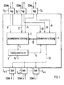
- Fig. 1 a network element is shown which e.g. Part of one after Standard for synchronous digital hierarchy (SDH) working Messaging system is.
- SDH synchronous digital hierarchy
- the network elements are connected to one another, for example by copper cables and / or optical fibers.
- the network element which is a cross-connect, for example, has a number of interface devices S 1 , ..., S x , ..., S x + i .
- FIG. 1 shows six interface devices S 1 , S 2 , S x , S x + 1 , S x + 2 , S x + i ;
- An SSM arrives at each interface device S 1 , S 2 , S x on the upper side, which are designated SSM 1 , SSM 2 and SSM x in accordance with the interface devices S 1 , S 2 , S x .
- An SSM for example with the message DNU, can also be transmitted from each interface device S 1 , S 2 , S x .
- the directions of the SSM are shown by arrows with a corresponding direction on the interface devices S 1 , S 2 , S x .
- the network element also has a selection device 1, which contains a clock filter, a clock generator 6 and a control device 7.
- Each interface device S 1 , S 2 , S x is connected to the selection device 1 via a connection 3, 2, 5.
- the selection device 1 is thereby supplied with the clocks of STM-N signals arriving at the interface devices S 1 , S 2 , S x .
- each interface device S 1 , S 2 , S x is connected to the control device 7 via a connection 8, 9, 10.
- the control device 7 is supplied with the SSM, SSM 2 , SSM x via these connections 8, 9, 10.
- the control device 7 is in turn connected to the selection device 1 via a control line 12, and to the clock generator 6 via a connection 11.
- the selection device 1 is connected to the clock generator 6 via a connection 4.
- the control device 7 is connected to the interface devices S x + 1 , S x + 2 , S x + i on the lower side via a connection 13.
- the clock which is passed on to other network elements, emerges at an output 14 of the clock generator 6.
- the output 14 is connected to each interface device S 1 , ... S x ... S x + i ; In Fig. 1 this is indicated for simplification by an arrow drawn in at the exit 14.
- the clock filter present in the selection device 1 is due to the ITU-T recommendation G.812 or G81s specifies and has the task Filter out clock disturbances (jitter and wander). Another The task of the clock filter is in the event of its failure Input signal the frequency of its output signal as constant as to keep possible.
- the control device 7 evaluates the incoming SSM, SSM 2 , SSM x and uses this to determine an interface device S 1 , S 2 , S x as the clock reference source.
- the selection device 1 is then controlled by the control device 7 such that the clock of the clock reference source is forwarded to the clock generator 6.
- the clock generator 6 is, for example, a phase locked loop (PLL) which, after synchronization to the clock coming from the selection device 6, passes this clock on via the output 14. If the clock generator 6 cannot be synchronized because, for example, too much noise accompanies the clock, or because the clock has failed, the clock generator 6 gives the control device 7 a corresponding message. Such a message causes, for example, the network element to go into a hold-over state.
- PLL phase locked loop
- the control device 7 generates an SSM which corresponds to the current state of the network element.
- This SSM can be one of the SSM 1 , SSM 2 , SSM x received at the interface devices S 1 , S 2 , S x on the upper side. However, it can also be a new SSM generated by the control device 7.
- the interface devices S x + 1 , S x + 2 , S x + 1 on the lower side each pass on the selected or generated SSM; incoming SSM are ignored.
- the directions of the SSM are shown by arrows with the corresponding direction.
- two classes top, bottom are defined for the interface devices S 1 , ..., S x , ... S x + i :
- the interface devices S 1 , S 2 , S x on the upper side have the class " top "and the interface devices S x + 1 , S x + 2 , S x + i on the lower side the class" bottom ".
- the classes "top, bottom” (abbreviated: bot) are shown in FIG. 1 at the interface devices S 1 , ..., S x , ..., S x + i .
- the interface devices S 1 , S 2 , S x of the "top” class represent possible clock reference sources, from which one is selected by the control device 7. This means that the interface devices S 1 , S 2 , S x of this class "top” are connected to interface devices of one or more other network elements, the SSM of which are generally accepted for synchronization. As already mentioned, the interface devices S x + 1 , S x + 2 , S x + i of the "bottom” class ignore incoming SSM, ie SSM arriving from other network elements is not used for synchronization.
- a Synchronization network even in a non-hierarchical Transmission and switching system to be created. It can by defining the classes "top, bottom" one Interface device can be determined whether the network element other network element may or may not synchronize.
- FIG. 2 shows an exemplary hierarchical synchronization network with nine network elements NE11 ... NE33. These network elements NE11 ... NE33 are shown in the form of a grid (3x3 matrix), the grid points representing the idealized geographic locations of the network elements NE11 ... NE33 and the grid lines the cable or radio connections between the network elements.
- a reference clock is fed into the hierarchical synchronization network at the network elements NE11, NE13, NE32.
- the reference clock (the "master clock”) is generated by a reference clock source, for example a cesium clock, which has a clock stability of 10 -11 .
- the network elements NE11, NE13, NE32 are shown as full circles and the remaining network elements NE12, N21 ... NE31, NE33, which have no reference clock source, as open circles.
- the classes "top” and “bottom” are indicated on the individual network elements NE11 ... NE33.
- the network elements NE11, NE13, NE32 only have Interface devices with the class "bottom"; from others Network elements cannot be synchronized.
- the network element NE21 only accepts one from the network element NE11 coming clock (class “top”) and ignores SSM by the Network elements NE22, NE31 come (class “bottom”).
Landscapes
- Engineering & Computer Science (AREA)
- Computer Networks & Wireless Communication (AREA)
- Signal Processing (AREA)
- Synchronisation In Digital Transmission Systems (AREA)
- Use Of Switch Circuits For Exchanges And Methods Of Control Of Multiplex Exchanges (AREA)
- Time-Division Multiplex Systems (AREA)
- Data Exchanges In Wide-Area Networks (AREA)
Claims (2)
- Elément de réseau pour un système de transmission de messages numérique, synchrone, comprenant :caractérisé en ce queplusieurs dispositifs d'interface (S1 ... Sx ... Sx+i) pour recevoir des signaux de message contenant respectivement un indicateur de qualité de synchronisation (SSM, SSM1, ..., SSMx),un générateur d'horloge (6) etun dispositif de sélection (1) pour sélectionner l'un des dispositifs d'interface à l'aide des indicateurs de qualité de synchronisation reçus (SSM1, ..., SSMx) comme source de référence d'horloge pour la synchronisation du générateur d'horloge (6),
les dispositifs d'interface (S1 ..., Sx, ..., Sx+i) sont divisés en deux classes (top, bot), les dispositifs d'interface (S1, ..., Sx) de la première classe (top) étant des sources de référence d'horloge possibles et les dispositifs d'interface (Sx+1, ..., Sx+i) de la deuxième classe (bot) n'étant pas utilisés pour la synchronisation. - Elément de réseau selon la revendication 1, comprenant un dispositif de commande (7) raccordé au dispositif de sélection (1), le dispositif de commande étant raccordé aux dispositifs d'interface (S1, ..., Sx) de la première classe (top) (8, 9, 10), dans lequel le dispositif de commande (7) est réalisé de telle sorte qu'il évalue des indicateurs de qualité de synchronisation (SSM1, ..., SSMx) reçus par les dispositifs d'interface (S1, ..., Sx) et sélectionne un dispositif d'interface (S1, ..., Sx) comme source de référence d'horloge, dont le cycle d'horloge est amené par le dispositif de sélection (1) au générateur d'horloge (6), dans lequel le générateur d'horloge (6) sert à vérifier le cycle d'horloge en vue de la capacité de synchronisation et à le retransmettre aux dispositifs d'interface (S1, ..., Sx+i), et dans lequel le dispositif de commande (7) est conçu pour retransmettre aux dispositifs d'interface (S1, ..., Sx+i) de la deuxième classe (bot) l'un des indicateurs de qualité de synchronisation (SSM1, ..., SSMx) ou un indicateur de qualité de synchronisation généré par celui-ci.
Priority Applications (1)
| Application Number | Priority Date | Filing Date | Title |
|---|---|---|---|
| EP00112542A EP1033838A2 (fr) | 1994-12-24 | 1995-12-21 | Système numérique de transmission avec réseau hiérarchique de synchronisation |
Applications Claiming Priority (2)
| Application Number | Priority Date | Filing Date | Title |
|---|---|---|---|
| DE4446511 | 1994-12-24 | ||
| DE4446511A DE4446511A1 (de) | 1994-12-24 | 1994-12-24 | Synchrones digitales Nachrichtenübertragungssystem mit hierarchischem Synchronisierungsnetz |
Related Child Applications (1)
| Application Number | Title | Priority Date | Filing Date |
|---|---|---|---|
| EP00112542A Division EP1033838A2 (fr) | 1994-12-24 | 1995-12-21 | Système numérique de transmission avec réseau hiérarchique de synchronisation |
Publications (3)
| Publication Number | Publication Date |
|---|---|
| EP0723344A2 EP0723344A2 (fr) | 1996-07-24 |
| EP0723344A3 EP0723344A3 (fr) | 1996-10-16 |
| EP0723344B1 true EP0723344B1 (fr) | 2000-09-20 |
Family
ID=6537053
Family Applications (2)
| Application Number | Title | Priority Date | Filing Date |
|---|---|---|---|
| EP95120268A Expired - Lifetime EP0723344B1 (fr) | 1994-12-24 | 1995-12-21 | Système numérique de transmission avec réseau hiérarchique de synchronisation |
| EP00112542A Withdrawn EP1033838A2 (fr) | 1994-12-24 | 1995-12-21 | Système numérique de transmission avec réseau hiérarchique de synchronisation |
Family Applications After (1)
| Application Number | Title | Priority Date | Filing Date |
|---|---|---|---|
| EP00112542A Withdrawn EP1033838A2 (fr) | 1994-12-24 | 1995-12-21 | Système numérique de transmission avec réseau hiérarchique de synchronisation |
Country Status (6)
| Country | Link |
|---|---|
| US (1) | US5886996A (fr) |
| EP (2) | EP0723344B1 (fr) |
| AU (1) | AU707590B2 (fr) |
| CA (1) | CA2166036A1 (fr) |
| DE (2) | DE4446511A1 (fr) |
| ES (1) | ES2151018T3 (fr) |
Families Citing this family (25)
| Publication number | Priority date | Publication date | Assignee | Title |
|---|---|---|---|---|
| JP3197793B2 (ja) * | 1995-07-03 | 2001-08-13 | 富士通株式会社 | 無線装置 |
| FI104665B (fi) * | 1996-09-30 | 2000-04-14 | Nokia Networks Oy | Hierarkkinen synkronointimenetelmä |
| FI104593B (fi) * | 1996-09-30 | 2000-02-29 | Nokia Networks Oy | Hierarkkinen synkronointimenetelmä |
| DE19653261A1 (de) * | 1996-12-20 | 1998-06-25 | Alsthom Cge Alcatel | Synchrones digitales Nachrichtenübertragungssystem, Steuerungseinrichtung, Netzelement und zentraler Taktgenerator |
| FI103307B (fi) * | 1997-02-11 | 1999-05-31 | Nokia Telecommunications Oy | Tietoliikenneverkon synkronointi |
| US6418151B1 (en) * | 1997-03-05 | 2002-07-09 | Lucent Technologies Inc. | Automatic primary reference clock switching for synchronous networks |
| US6574245B1 (en) * | 1997-12-26 | 2003-06-03 | Lucent Technologies Inc. | Enhanced synchronization status messaging |
| EP0982888A1 (fr) * | 1998-08-28 | 2000-03-01 | Siemens Aktiengesellschaft | Système de télécommunication et méthode pour le synchroniser et transmettre des données |
| EP0982890A1 (fr) * | 1998-08-28 | 2000-03-01 | Siemens Aktiengesellschaft | Système de télécommunication et méthode de génération d'horloge maítre dans ce système |
| DE19901588A1 (de) * | 1999-01-16 | 2000-07-20 | Alcatel Sa | Synchronisation eines Netzelementes in einem synchronen digitalen Nachrichtenübertragungsnetz |
| JP3761732B2 (ja) * | 1999-01-19 | 2006-03-29 | 富士通株式会社 | ネットワーク同期制御装置 |
| JP3485250B2 (ja) * | 1999-02-17 | 2004-01-13 | 富士通株式会社 | 従属同期装置及び該従属同期装置を有するsdh装置 |
| DE19910349A1 (de) * | 1999-03-09 | 2000-10-05 | Siemens Ag | Verfahren zur Synchronisation von Netzelementen eines Netzes |
| US6714563B1 (en) * | 1999-04-26 | 2004-03-30 | Cisco Technology, Inc. | Network clock synchronization scheme |
| GB2353173B (en) * | 1999-08-10 | 2001-09-19 | Marconi Comm Ltd | Communications system |
| GB2355898B (en) * | 1999-10-26 | 2002-07-03 | Marconi Comm Ltd | Communications system |
| DE19959815A1 (de) | 1999-12-11 | 2001-06-21 | Alcatel Sa | Synchrones digitales Nachrichtenübertragungssystem |
| DE19959813B4 (de) | 1999-12-11 | 2004-02-05 | Alcatel | Synchrones digitales Nachrichtenübertragungssystem |
| DE10207283B4 (de) * | 2002-02-21 | 2005-07-07 | Winbond Electronics Corp. | Integrated Services Digital Network (ISDN)- Nebenstellenanlage, befähigt, einen Synchronisationstaktgeber automatisch zu wählen |
| AU2002349257A1 (en) * | 2002-11-06 | 2004-06-07 | Wuhan Fiberhome Networks Co., Ltd. | Multiple service ring of n-ringlet structure based on multiple fe, ge and 10ge |
| US7505450B2 (en) * | 2005-03-23 | 2009-03-17 | Cisco Technology, Inc. | Configuration of failure and acquire timeouts to facilitate recovery from failures in hierarchical mesh networks |
| US8088548B2 (en) * | 2007-10-23 | 2012-01-03 | Az Electronic Materials Usa Corp. | Bottom antireflective coating compositions |
| CN101931524A (zh) * | 2009-06-25 | 2010-12-29 | 中兴通讯股份有限公司 | 一种同步数字传输网的时钟源选择方法 |
| US9252904B2 (en) * | 2011-06-01 | 2016-02-02 | Coriant Operations, Inc. | Method and apparatus for distributing network timing in a mesh optical network |
| CN102664699A (zh) * | 2012-04-12 | 2012-09-12 | 中兴通讯股份有限公司南京分公司 | 微波网元的时钟源选择方法及装置 |
Family Cites Families (11)
| Publication number | Priority date | Publication date | Assignee | Title |
|---|---|---|---|---|
| US4696019A (en) * | 1984-09-19 | 1987-09-22 | United Technologies Corporation | Multi-channel clock synchronizer |
| US4933836A (en) * | 1986-10-29 | 1990-06-12 | United Technologies Corporation | n-Dimensional modular multiprocessor lattice architecture |
| US5291489A (en) * | 1987-11-13 | 1994-03-01 | Dsc Communications Corporation | Interprocessor switching network |
| US4977582A (en) * | 1988-03-31 | 1990-12-11 | At&T Bell Laboratories | Synchronization of non-continuous digital bit streams |
| DE3916850A1 (de) * | 1988-05-21 | 1990-12-06 | Telefonbau & Normalzeit Gmbh | Verfahren zur digitalen informationsuebertragung fuer kommunikations-vermittlungssysteme |
| US5185736A (en) * | 1989-05-12 | 1993-02-09 | Alcatel Na Network Systems Corp. | Synchronous optical transmission system |
| DE4012762A1 (de) * | 1990-04-21 | 1991-10-24 | Standard Elektrik Lorenz Ag | Verfahren zur synchronisation eines nach einer digitalen synchronen hierarchie rahmenstrukturierten systemes |
| CA2054591C (fr) * | 1991-02-28 | 1996-09-03 | Giovanni Vannucci | Systemes de telecommunication sans fil |
| GB9126505D0 (en) * | 1991-12-13 | 1992-02-12 | Plessey Telecomm | Telecommunications system and method |
| JP3168487B2 (ja) * | 1993-03-15 | 2001-05-21 | 富士通株式会社 | 同期確立チェック方法及び伝送装置 |
| US5675580A (en) * | 1993-12-30 | 1997-10-07 | Dsc Communications Corporation | Processor device for terminating and creating synchronous transport signals |
-
1994
- 1994-12-24 DE DE4446511A patent/DE4446511A1/de not_active Withdrawn
-
1995
- 1995-12-14 AU AU40417/95A patent/AU707590B2/en not_active Ceased
- 1995-12-15 US US08/573,388 patent/US5886996A/en not_active Expired - Fee Related
- 1995-12-21 EP EP95120268A patent/EP0723344B1/fr not_active Expired - Lifetime
- 1995-12-21 EP EP00112542A patent/EP1033838A2/fr not_active Withdrawn
- 1995-12-21 ES ES95120268T patent/ES2151018T3/es not_active Expired - Lifetime
- 1995-12-21 DE DE59508732T patent/DE59508732D1/de not_active Expired - Fee Related
- 1995-12-22 CA CA002166036A patent/CA2166036A1/fr not_active Abandoned
Also Published As
| Publication number | Publication date |
|---|---|
| AU4041795A (en) | 1996-07-04 |
| AU707590B2 (en) | 1999-07-15 |
| EP0723344A2 (fr) | 1996-07-24 |
| CA2166036A1 (fr) | 1996-06-25 |
| EP1033838A2 (fr) | 2000-09-06 |
| DE59508732D1 (de) | 2000-10-26 |
| EP0723344A3 (fr) | 1996-10-16 |
| US5886996A (en) | 1999-03-23 |
| ES2151018T3 (es) | 2000-12-16 |
| DE4446511A1 (de) | 1996-06-27 |
Similar Documents
| Publication | Publication Date | Title |
|---|---|---|
| EP0723344B1 (fr) | Système numérique de transmission avec réseau hiérarchique de synchronisation | |
| DE69528928T2 (de) | Zweifaserring mit auswählender Schutzfunktion für Synchrone Digitale Hierarchie (SDH) | |
| DE3500512C2 (de) | Zeitmultiplex-Ring | |
| EP1021009B1 (fr) | Synchronisation d'élément de réseau dans un réseau de communication synchrone numérique | |
| EP0429888B1 (fr) | Méthode de transmission par un réseau multiplex hierarchisé synchrone et numérique d'un signal à large bande distribué entre des unités de transmission subordonnées | |
| DE69434789T2 (de) | Kommunikationssystem bestehend aus miteinander verbundenen, weggeschaltenen Ringübertragungssystemen | |
| EP0849904B1 (fr) | Système de transmission digitale synchrone, unité de régulation, élément de réseau et générateur d'horloge central | |
| DE69132247T2 (de) | Phasenverriegelte Schleifenanordnung | |
| EP1051057A2 (fr) | Transport de conteneurs concaténées dans une réseau de transmission synchrone | |
| DE69228370T2 (de) | Verfahren zur synchronisierung eines synchronen datenkommunikationsnetzwerkes und kommunikationsvorrichtung zum gebrauch im synchronen datenkommunikationsnetzwerk | |
| EP0895680B1 (fr) | Systeme de transmission synchrone avec fonction de localisation d'erreur, et appareil de controle associe | |
| DE60030643T2 (de) | Telekommunikationssystem | |
| DE69329343T2 (de) | Netzwerkanordnung | |
| DE60034412T2 (de) | Kommunikationssystem | |
| DE69429086T2 (de) | Verfahren zur synchronisation von verbundenen sdh- und pdh-fernmeldenetzen | |
| DE69738078T2 (de) | System und verfahren zur timing-kontrolle in einem distribuierten digitalen cross-connect-system | |
| DE69924902T2 (de) | Funkstation für ein SDH-Netzwerk und Verfahren zur Auswahl des Arbeitstakts davon | |
| DE19959815A1 (de) | Synchrones digitales Nachrichtenübertragungssystem | |
| DE60130480T2 (de) | Verfahren und vorrichtung zur datenübertragung über einen tdm-bus | |
| EP0530393A1 (fr) | Méthode et dispositif pour la synchronisation d'un générateur d'horloge d'un système de commutation de communication | |
| EP0565890A2 (fr) | Méthode et dispositif de transmission d'un signal numérique par un support VC-12 sur des canaux de données | |
| EP0993711B1 (fr) | Procede et circuit pour l'adaptation et la commutation d'un flux de donnees | |
| EP0773645B1 (fr) | Méthode de sélection de signaux concaténés à partir d'un signal reçu selon la hiérarchie numérique synchrone (SDH) | |
| DE19608621C2 (de) | Telekommunikationsnetzwerk | |
| DE3901868C1 (en) | Channel distributor for plesiochronous signals |
Legal Events
| Date | Code | Title | Description |
|---|---|---|---|
| PUAI | Public reference made under article 153(3) epc to a published international application that has entered the european phase |
Free format text: ORIGINAL CODE: 0009012 |
|
| AK | Designated contracting states |
Kind code of ref document: A2 Designated state(s): CH DE ES FR GB IT LI SE |
|
| PUAL | Search report despatched |
Free format text: ORIGINAL CODE: 0009013 |
|
| AK | Designated contracting states |
Kind code of ref document: A3 Designated state(s): CH DE ES FR GB IT LI SE |
|
| 17P | Request for examination filed |
Effective date: 19961120 |
|
| 17Q | First examination report despatched |
Effective date: 19990722 |
|
| GRAG | Despatch of communication of intention to grant |
Free format text: ORIGINAL CODE: EPIDOS AGRA |
|
| GRAG | Despatch of communication of intention to grant |
Free format text: ORIGINAL CODE: EPIDOS AGRA |
|
| GRAH | Despatch of communication of intention to grant a patent |
Free format text: ORIGINAL CODE: EPIDOS IGRA |
|
| GRAH | Despatch of communication of intention to grant a patent |
Free format text: ORIGINAL CODE: EPIDOS IGRA |
|
| GRAA | (expected) grant |
Free format text: ORIGINAL CODE: 0009210 |
|
| RAP1 | Party data changed (applicant data changed or rights of an application transferred) |
Owner name: ALCATEL |
|
| AK | Designated contracting states |
Kind code of ref document: B1 Designated state(s): CH DE ES FR GB IT LI SE |
|
| ITF | It: translation for a ep patent filed | ||
| REG | Reference to a national code |
Ref country code: CH Ref legal event code: EP |
|
| GBT | Gb: translation of ep patent filed (gb section 77(6)(a)/1977) |
Effective date: 20000920 |
|
| REF | Corresponds to: |
Ref document number: 59508732 Country of ref document: DE Date of ref document: 20001026 |
|
| PGFP | Annual fee paid to national office [announced via postgrant information from national office to epo] |
Ref country code: GB Payment date: 20001115 Year of fee payment: 6 |
|
| REG | Reference to a national code |
Ref country code: CH Ref legal event code: NV Representative=s name: CABINET ROLAND NITHARDT CONSEILS EN PROPRIETE INDU |
|
| PGFP | Annual fee paid to national office [announced via postgrant information from national office to epo] |
Ref country code: CH Payment date: 20001120 Year of fee payment: 6 |
|
| ET | Fr: translation filed | ||
| PGFP | Annual fee paid to national office [announced via postgrant information from national office to epo] |
Ref country code: SE Payment date: 20001204 Year of fee payment: 6 Ref country code: FR Payment date: 20001204 Year of fee payment: 6 |
|
| PGFP | Annual fee paid to national office [announced via postgrant information from national office to epo] |
Ref country code: DE Payment date: 20001213 Year of fee payment: 6 |
|
| REG | Reference to a national code |
Ref country code: ES Ref legal event code: FG2A Ref document number: 2151018 Country of ref document: ES Kind code of ref document: T3 |
|
| PGFP | Annual fee paid to national office [announced via postgrant information from national office to epo] |
Ref country code: ES Payment date: 20001218 Year of fee payment: 6 |
|
| PLBE | No opposition filed within time limit |
Free format text: ORIGINAL CODE: 0009261 |
|
| STAA | Information on the status of an ep patent application or granted ep patent |
Free format text: STATUS: NO OPPOSITION FILED WITHIN TIME LIMIT |
|
| 26N | No opposition filed | ||
| PG25 | Lapsed in a contracting state [announced via postgrant information from national office to epo] |
Ref country code: SE Free format text: LAPSE BECAUSE OF NON-PAYMENT OF DUE FEES Effective date: 20011222 |
|
| PG25 | Lapsed in a contracting state [announced via postgrant information from national office to epo] |
Ref country code: LI Free format text: LAPSE BECAUSE OF NON-PAYMENT OF DUE FEES Effective date: 20011231 Ref country code: CH Free format text: LAPSE BECAUSE OF NON-PAYMENT OF DUE FEES Effective date: 20011231 |
|
| PG25 | Lapsed in a contracting state [announced via postgrant information from national office to epo] |
Ref country code: DE Free format text: LAPSE BECAUSE OF NON-PAYMENT OF DUE FEES Effective date: 20020702 |
|
| EUG | Se: european patent has lapsed |
Ref document number: 95120268.8 |
|
| REG | Reference to a national code |
Ref country code: CH Ref legal event code: PL |
|
| PG25 | Lapsed in a contracting state [announced via postgrant information from national office to epo] |
Ref country code: FR Free format text: LAPSE BECAUSE OF NON-PAYMENT OF DUE FEES Effective date: 20020830 |
|
| REG | Reference to a national code |
Ref country code: FR Ref legal event code: ST |
|
| PG25 | Lapsed in a contracting state [announced via postgrant information from national office to epo] |
Ref country code: ES Free format text: LAPSE BECAUSE OF NON-PAYMENT OF DUE FEES Effective date: 20021222 |
|
| REG | Reference to a national code |
Ref country code: ES Ref legal event code: FD2A Effective date: 20030113 |
|
| PG25 | Lapsed in a contracting state [announced via postgrant information from national office to epo] |
Ref country code: IT Free format text: LAPSE BECAUSE OF NON-PAYMENT OF DUE FEES;WARNING: LAPSES OF ITALIAN PATENTS WITH EFFECTIVE DATE BEFORE 2007 MAY HAVE OCCURRED AT ANY TIME BEFORE 2007. THE CORRECT EFFECTIVE DATE MAY BE DIFFERENT FROM THE ONE RECORDED. Effective date: 20051221 |
|
| PG25 | Lapsed in a contracting state [announced via postgrant information from national office to epo] |
Ref country code: GB Free format text: LAPSE BECAUSE OF NON-PAYMENT OF DUE FEES Effective date: 20011221 |