EP0723143A1 - Vorrichtung zur Messung von Druck oder Differenzdruck - Google Patents
Vorrichtung zur Messung von Druck oder Differenzdruck Download PDFInfo
- Publication number
- EP0723143A1 EP0723143A1 EP95100337A EP95100337A EP0723143A1 EP 0723143 A1 EP0723143 A1 EP 0723143A1 EP 95100337 A EP95100337 A EP 95100337A EP 95100337 A EP95100337 A EP 95100337A EP 0723143 A1 EP0723143 A1 EP 0723143A1
- Authority
- EP
- European Patent Office
- Prior art keywords
- housing
- pressure
- pressure sensor
- measuring medium
- sealing element
- Prior art date
- Legal status (The legal status is an assumption and is not a legal conclusion. Google has not performed a legal analysis and makes no representation as to the accuracy of the status listed.)
- Granted
Links
Images
Classifications
-
- G—PHYSICS
- G01—MEASURING; TESTING
- G01L—MEASURING FORCE, STRESS, TORQUE, WORK, MECHANICAL POWER, MECHANICAL EFFICIENCY, OR FLUID PRESSURE
- G01L9/00—Measuring steady of quasi-steady pressure of fluid or fluent solid material by electric or magnetic pressure-sensitive elements; Transmitting or indicating the displacement of mechanical pressure-sensitive elements, used to measure the steady or quasi-steady pressure of a fluid or fluent solid material, by electric or magnetic means
- G01L9/0041—Transmitting or indicating the displacement of flexible diaphragms
- G01L9/0072—Transmitting or indicating the displacement of flexible diaphragms using variations in capacitance
- G01L9/0075—Transmitting or indicating the displacement of flexible diaphragms using variations in capacitance using a ceramic diaphragm, e.g. alumina, fused quartz, glass
-
- G—PHYSICS
- G01—MEASURING; TESTING
- G01L—MEASURING FORCE, STRESS, TORQUE, WORK, MECHANICAL POWER, MECHANICAL EFFICIENCY, OR FLUID PRESSURE
- G01L19/00—Details of, or accessories for, apparatus for measuring steady or quasi-steady pressure of a fluent medium insofar as such details or accessories are not special to particular types of pressure gauges
- G01L19/06—Means for preventing overload or deleterious influence of the measured medium on the measuring device or vice versa
- G01L19/0627—Protection against aggressive medium in general
-
- G—PHYSICS
- G01—MEASURING; TESTING
- G01L—MEASURING FORCE, STRESS, TORQUE, WORK, MECHANICAL POWER, MECHANICAL EFFICIENCY, OR FLUID PRESSURE
- G01L19/00—Details of, or accessories for, apparatus for measuring steady or quasi-steady pressure of a fluent medium insofar as such details or accessories are not special to particular types of pressure gauges
- G01L19/14—Housings
- G01L19/142—Multiple part housings
- G01L19/144—Multiple part housings with dismountable parts, e.g. for maintenance purposes or for ensuring sterile conditions
Definitions
- the invention relates to a device for measuring pressure or differential pressure with a ceramic pressure sensor.
- a disadvantage of such a device is that the sealing element, which is in constant contact with the measuring medium, cannot be replaced without the pressure sensor having to be removed from the housing. After replacing the sealing element, the device must be calibrated again.
- this replacement is not only necessary in the event of a replacement, but also when cleaning, especially when the device is used in the food industry. This is because the sealing elements built in there form potential bacterial nests.
- a device of this type is not suitable for highly viscous and / or sticky media, since such media block the axial inner bore of the connecting element and thus impair the pressure transmission.
- the pressure sensor has a pressure-sensitive membrane and the housing and the connecting element are each provided with a central opening through which the pressure membrane is in contact with the measuring medium.
- the housing closes on its side facing the measuring medium with a retaining ring projecting into the interior of the housing, which has a groove for receiving the outer sealing element and the pressure sensor is pressed against the outer sealing element.
- the connecting element engages around the housing on the side facing the measuring medium and presses the inner sealing element against a pressure-insensitive edge of the pressure sensor, the inner sealing element on the side facing the measuring medium on the connecting element, on the side facing away from the measuring medium Pressure sensor and on the outside of the housing and on the inside is touched by the measuring medium.
- a further advantageous embodiment of the invention is that the measuring medium does not touch the housing.
- the housing is pressure-tightly connected to the connection element via the outer sealing element, and the housing and the connection element are screwed together.
- connection element can be releasably connected to the wall of the container in a pressure-tight manner and can consist of a material which is resistant to the measuring medium, preferably of Hastelloy, titanium, tantalum, Monel, nickel or Inconel.
- An advantage of the invention is that the device has a largely flat front surface and no bottlenecks through which the measuring medium is passed.
- Another advantage of the invention is that the device allows the sealing element that is in contact with the measuring medium to be replaced without the device having to be calibrated again and without the need for components that function as diaphragm seals.
- Another advantage of the invention is that the device can be used as a universal component for a large number of process connections due to the releasably connected connection element and that expensive storage with many replacement parts that are required due to hygiene regulations and / or due to heavy contamination can be avoided.
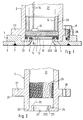
- the device for measuring pressure or differential pressure consists of three main elements: a pressure sensor 1, a housing 2 and a connection element 3 detachably connected to the housing.
- the latter serves to fasten the device to a wall 6 of a container containing a measuring medium.
- An outer sealing element 4 is located between the housing 2 and the pressure sensor 1 on the side facing the measuring medium.
- An exchangeable inner sealing element 9 is arranged between the pressure sensor 1 and the connecting element 3. The two sealing elements 4, 9 grip coaxially.
- the pressure sensor 1 is, for example, conventional capacitive, cylindrical pressure measuring cell, which consists of a membrane 11 and a base body 12, which are connected by a connecting material, e.g. an active brazing alloy, held at a defined distance from one another and hermetically sealed together.
- a connecting material e.g. an active brazing alloy
- the inner surfaces of the membrane 11 and the base body 12 coated with electrode material form at least one measuring capacitor, the capacitance of which depends on the deflection of the membrane 11 and is thus a measure of the pressure applied to the membrane 11.
- the membrane 11 can consist of ceramic, oxide ceramic, quartz, sapphire or a crystalline material.
- the base body 12 preferably consists of a material that is very similar to the material of the membrane 11, or at least has a comparable coefficient of thermal expansion.
- the pressure measuring cell On the side facing away from the measuring medium, the pressure measuring cell has an electronic circuit 13 which converts the capacitance of the measuring capacitor into a pressure-dependent electrical signal and makes it accessible for further processing and / or display via electrical connecting lines 14.
- the pressure sensor 1 is introduced into the rotationally symmetrical housing 2 in such a way that the pressure-sensitive membrane 11 faces the measuring medium.
- the electrical connection lines 14 run in the interior of the housing on the back of the pressure sensor 1 facing away from the measuring medium.
- Figure 2 shows the housing 2 as an individual part.
- the inside diameter of a cylindrical interior 21 of the housing 2 is constant and corresponds to the outside diameter of the pressure sensor 1.
- the housing 2 and the connection element 3 each have a central opening 23, 31 through which the membrane 11 is in contact with the measuring medium.
- the central opening 31 of the connection element 3 is constructed in such a way that almost the entire membrane 11 of the pressure sensor 1 is connected to the measuring medium. This ensures good utilization of the sensitivity of the pressure sensor 1 and the device is easy to clean.
- the housing 2 On the side facing the measuring medium, the housing 2 is a retaining ring 22 with a ring-cylindrical ring which extends radially into the interior 21 of the housing 2 Bund 221 trained.
- the diameter of the central, circular opening 23 of the housing 2 is equal to the inner diameter of the annular cylindrical collar 221 of the mounting ring 22.
- the retaining ring 22 has a groove 24 in the interior 21 of the housing 2 on the side facing the pressure sensor with e.g. rectangular cross-section, the outer diameter of which corresponds to the diameter of the interior 21.
- the outer sealing element 4 lies in this groove 24.
- an O-ring made of an elastomer and has the function of protecting the electronic circuit 13 arranged on the back of the pressure sensor 1 against contamination and / or moisture.
- This arrangement has the advantage that the pressure sensor characteristic is constant over wide temperature ranges, since the pressure sensor 1 is clamped in a defined manner.
- this form which consists of pressure sensor 1, housing 2, outer sealing element 4, threaded ring 5, electronic circuit 13 and the electrical connecting lines 14, a pressure measuring device which is itself fully functional is already available.
- the connecting element 3 engages around the collar 221 of the mounting ring 22 such that there is a gap 10 between the pressure membrane 11 and the connecting element 3 in the edge region of the pressure sensor 1.
- the sealing element 9 bears on the connecting element 3, on the side facing away from the measuring medium on the pressure sensor 1 and on the outside on the housing 2. It is touched by the measuring medium on the inside.
- the sealing element 9 consists of a material resistant to the measuring medium. Depending on the medium, this is e.g. B. a Viton O-ring, a Kalrez seal or a polytetrafluoroethylene coated Viton seal.
- the housing 2 is not in contact with the measuring medium.
- the connection element 3 completely surrounds the mounting ring 22.
- this has a shoulder ring 27 with at least two bores 28 at the level of the surface of the pressure sensor 1 facing away from the measuring medium, through which the housing 2 is connected to the connection element 3 by means of screws 8.
- the housing 2 with the heel ring 27 lies tightly on the connecting element 3 and this on the lower housing edge tightly on the mounting ring 22 on the side opposite the groove 24. This ensures that the gap 10, in which the inner sealing element 9 is located, always has the same dimensions and the inner sealing element 9 experiences the same pressing force with each installation.
- connection element 3 and the inner sealing element 9 are the only components of the device which come into contact with the measuring medium. Only these two parts must therefore be resistant to the measuring medium.
- the material of the connecting element 3 is an expensive special material, such as titanium, tantalum, nickel, Monel, Inconell or Hastelloy.
- the material of the housing 2 can be a standard material, such as aluminum or steel, which is inexpensive in comparison to this.
- connection element 3 is fastened to the container wall 6 by means of a process connection 7.
- process connection 7 is only shown schematically. While the internal geometry of the connecting element 3 is identical for all applications, there are many variants for the external geometry of the connecting element 3, for example the design as a flange that is screwed to a measuring flange at the measuring location, the design as an external thread that goes into a corresponding opening is screwed in or the design as a turned part which is welded into a container opening 6. Further detachable or non-detachable process connections 7 are known to the person skilled in the art.
- the connecting element 3 thus fulfills two tasks. On the one hand, it ensures reproducible, i.e. a clamping of the sealing element 9 which does not change the pressure sensor characteristic, on the other hand it functions as an adapter by means of which the actual pressure sensor arrangement, i.e. the pressure sensor 1, the housing 2, the outer sealing element 4, the threaded ring 5, the electronic circuit 13 and the electrical connecting lines 14, as a universal component, is attached to one of many possible process connections on the container wall 6.
Abstract
Description
- Die Erfindung betrifft eine Vorrichtung zur Messung von Druck oder Differenzdruck mit einem keramischen Drucksensor.
- In der DE-A 42 34 290 ist eine Vorrichtung zur Druckmessung beschrieben
- mit einem rotationssymmetrischen keramischen Drucksensor,
- mit einem rotationssymmetrischen, eine axiale Bohrung aufweisenden Gehäuse,
- -- deren Durchmesser in Richtung der dem Meßmedium zugewandten Frontseite abnimmt, und
- mit einem einzigen, zwischen Gehäuse und der Mantelfläche des Drucksensor frontbündig eingesetzten Dichtelement.
- Ein Nachteil einer solchen Vorrichtung ist, daß das Dichtelement, das ständig mit dem Meßmedium in Berührung steht, nicht ausgewechselt werden kann, ohne daß der Drucksensor aus dem Gehäuse entnommen werden muß. Nach dem Auswechseln des Dichtelements ist eine erneute Kalibrierung der Vorrichtung erforderlich.
- Dieses Auswechseln ist aber nicht nur im Ersatzfall, sondern auch bei der Reinigung nötig, insb. dann, wenn die Vorrichtung in der Lebensmittelindustrie verwendet wird. Denn dort bilden in der vorbeschriebenen Art eingebaute Dichtelemente potentielle Bakteriennester.
- In der DE-A 42 13 857 ist ferner eine Vorrichtung zur Messung von Druck oder Differenzdruck beschrieben mit
- einem keramischen Drucksensor,
- einem Gehäuse,
- einem lösbar mit dem Gehäuse verbundenen Anschlußelement zur Befestigung der Vorrichtung an einer Wand eines ein Meßmedium enthaltenden Behälters,
- -- wobei das Anschlußelement eine enge, axiale Innenbohrung aufweist, die die Funktion eines Druckmittlers besitzt und durch die der Drucksensor mit dem Meßmedium in Berührung steht und mit
- einem zwischen Gehäuse, Anschlußelement und Drucksensor auf der dem Meßmedium zugewandten Seite eingefügten, auswechselbaren Dichtelement, das mit definierter Kraft eingespannt ist, indem das Anschlußelement gegen einen Anschlag geschraubt ist.
- Eine Vorrichtung dieser Art eignet sich jedoch nicht für hochviskose und/oder klebrige Medien, da solche Medien die axiale Innenbohrung des Anschlußelementes blockieren und damit die Druckübertragung beeinträchtigen.
- Es ist eine Aufgabe der Erfindung, eine Vorrichtung zur Druck- oder zur Differenzdruck-Messung anzugeben, die insb. für hochviskose und/oder klebrige Lebensmittel geeignet und leicht zu reinigen ist, ohne daß die elektrischen Eigenschaften beinträchtigt werden.
- Hierzu besteht die Erfindung in einer Vorrichtung zur Messung von Druck oder Differenzdruck mit
- einem keramischen Drucksensor,
- einem Gehäuse,
- einem lösbar mit dem Gehäuse verbundenen Anschlußelement zur Befestigung der Vorrichtung an einer Wand eines ein Meßmedium enthaltenden Behälters,
- einem zwischen Gehäuse und Drucksensor auf der dem Meßmedium zugewandten Seite eingefügten äußeren Dichtelement und
- einem zwischen Drucksensor und Anschlußelement angeordneten, auswechselbaren inneren Dichtelement,
- -- welche Dichtelemente sich koaxial umgreifen.
- Gemäß einer vorteilhaften Ausgestaltung der Erfindung weist der Drucksensor eine druckempfindliche Membran auf und das Gehäuse und das Anschlußelement sind jeweils mit einer zentralen Öffnung versehen, durch die hindurch die Druckmembran mit dem Meßmedium in Berührung steht.
- Nach einer vorteilhaften Weiterbildung der Erfindung schließt das Gehäuse auf seiner dem Meßmedium zugewandten Seite mit einem in das Gehäuse-Innere ragenden Halterungsring ab, der eine Nut zur Aufnahme des äußeren Dichtelements aufweist und wobei der Drucksensor gegen das äußere Dichtelement gepreßt ist.
- Nach einer weiteren vorteilhaften Ausgestaltung umgreift das Anschlußelement das Gehäuse auf der dem Meßmedium zugewandten Seite und preßt das innere Dichtelement gegen einen druck-unempfindlichen Rand des Drucksensors, wobei das innere Dichtelement auf der dem Meßmedium zugewandten Seite am Anschlußelement, auf der vom Meßmedium abgewandten Seite am Drucksensor und auf der Außenseite am Gehäuse anliegt sowie auf der Innenseite vom Meßmedium berührt ist.
- Eine weitere vorteilhafte Ausgestaltung der Erfindung besteht darin, daß das das Meßmedium das Gehäuse nicht berührt.
- Nach einer weiteren vorteilhaften Ausgestaltung der Erfindung ist das Gehäuse über das äußere Dichtelement druckdicht mit dem Anschlußelement verbunden, und das Gehäuse und das Anschlußelement sind miteinander verschraubt.
- Weiterhin kann das Anschlußelement druckdicht mit der Wand des Behälters lösbar verbunden sein und aus einem gegenüber dem Meßmedium beständigen Material, vorzugsweise aus Hastelloy, Titan, Tantal, Monel, Nickel oder Inconel, bestehen.
- Ein Vorteil der Erfindung besteht darin, daß die Vorrichtung eine weitgehend ebene Frontfläche und keinerlei Engpässe aufweist, durch die das Meßmedium geleitet wird.
- Ein weiterer Vorteil der Erfindung besteht darin, daß die Vorrichtung das Auswechseln des mit dem Meßmedium in Berührung stehenden Dichtelements erlaubt, ohne daß eine erneute Kalibrierung der Vorrichtung notwendig ist und ohne daß Bauteile erforderlich sind, die ihrer Funktion nach Druckmittler sind.
- Ein weiterer Vorteil der Erfindung ist, daß die Vorrichtung durch das lösbar verbundene Anschlußelement als Universalbaustein für eine Vielzahl von Prozeßanschlüssen einsetzbar ist und daß aufwendige Lagerhaltung mit vielen Austauschteilen die auf Grund von Hygienebestimmungen und/oder-wegen starken Verunreinigungen erforderlich sind, vermeidbar ist.
- Die Erfindung und weitere Vorteile werden nun anhand der Zeichnungen, in denen ein Ausführungsbeispiel dargestellt ist näher erläutert.
- Fig. 1 zeigt:
- einen Längsschnitt durch eine erfindungsgemäße Vorrichtung und
- Fig. 2 zeigt:
- einen Längsschnitt durch das in Fig. 1 dargestellte Gehäuse.
- In Fig. 1 besteht die Vorrichtung zur Messung von Druck oder Differenzdruck aus drei Hauptelementen: einem Drucksensor 1, einem Gehäuse 2 und einem lösbar mit dem Gehäuse verbundenen Anschlußelement 3. Letzteres dient der Befestigung der Vorrichtung an einer Wand 6 eines ein Meßmedium enthaltenden Behälters. Zwischen dem Gehäuse 2 und dem Drucksensor 1 befindet sich auf der meßmedium-zugewandten Seite ein äußeres Dichtelement 4. Zwischen dem Drucksensor 1 und dem Anschlußelement 3 ist ein auswechselbares inneres Dichtelement 9 angeordnet. Die beiden Dichtelemente 4, 9 umgreifen sich koaxial.
- Der Drucksensor 1 ist beispielsweise übliche kapazitive, zylindrische Druckmeßzelle, die aus einer Membran 11 und einem Grundkörper 12 besteht, die durch ein Verbindungsmaterial, z.B. ein Aktivhartlot, in einem definierten Abstand von einander gehalten und mit einander hermetisch dicht verbunden sind. Die mit Elektrodenmaterial beschichteten Innenflächen der Membran 11 und des Grundkörper 12 bilden mindestens einen Meßkondensator, dessen Kapazität von der Durchbiegung der Membran 11 abhängt und somit ein Maß für den an der Membran 11 anliegenden Druck ist.
- Die Membran 11 kann aus Keramik, Oxidkeramik, Quarz, Saphir oder einem kristallinen Werkstoff bestehen. Der Grundkörper 12 besteht vorzugsweise aus einem Material, das dem Werkstoff der Membran 11 sehr ähnlich ist, oder zumindest einen vergleichbaren thermischen Ausdehnungskoeffizienten aufweist.
- Auf der meßmedium-abgewandten Seite weist die Druckmeßzelle eine elektronische Schaltung 13 auf, die die Kapazität des Meßkondensators in ein druckabhängiges elektrisches Signal umwandelt und über elektrische Anschlußleitungen 14 einer weiteren Verarbeitung und/oder Anzeige zugänglich macht.
- Aber auch andere Arten von Drucksensoren, z.B. Drucksensoren, die mit Dehnungsmeßstreifen arbeiten, sind bei der Erfindung einsetzbar.
- Der Drucksensor 1 ist in das rotationssymmetrisches Gehäuse 2 so eingebracht, daß die druckempfindliche Membran 11 dem Meßmedium zugewandt ist. Die elektrischen Anschlußleitungen 14 verlaufen im Gehäuse-Inneren auf der meßmediumabgewandten Rückseite des Drucksensors 1.
- Figur 2 zeigt das Gehäuse 2 als Einzelteil. Der Innendurchmesser eines zylindrischen Innenraumes 21 des Gehäuses 2 ist konstant und entspricht dem Außendurchmesser des Drucksensors 1.Das Gehäuse 2 und das Anschlußelement 3 weisen jeweils eine zentrale Öffnung 23, 31 auf, durch die hindurch die Membran 11 mit dem Meßmedium in Berührung steht. Die zentrale Öffnung 31 des Anschlußelementes 3 ist so konstruiert, daß nahezu die gesamte Membran 11 des Drucksensors 1 mit dem Meßmedium in Verbindung steht. Dadurch ist eine gute Ausnutzung der Empfindlichkeit des Drucksensors 1 gewährleistet und die Vorrichtung ist leicht zu reinigen.
- Die Querschnittsfläche der Öffnung 31 nimmt in Richtung der dem Meßmedium zugewandten Seite dadurch zu, daß der Rand der Öffnung 31 im Längsschnitt einen Viertelkreis 32 beschreibt, vgl. Fig. 1. Die dem Meßmedium zugewandte Fläche des Anschlußelements 3 fluchtet mit der Behälterwand 6. Das Anschlußelement 3 erstreckt sich nur soweit vor den Randbereich des Drucksensor 1, wie dies zur Befestigung des inneren Dichtelementes 9 nötig ist. Wegen dieser mit dem Drucksensor 1 praktisch frontbündigen Ausbildung des Anschlußelements 3 ist die Vorrichtung gut zu reinigen.
- Auf der dem Meßmedium zugewandten Seite ist das Gehäuse 2 als sich radial in den Innenraum 21 des Gehäuses 2 erstreckender Halterungsring 22 mit einem ringzylindrischen Bund 221 ausgebildet. Der Durchmesser der zentralen, kreisförmigen Öffnung 23 des Gehäuses 2 ist gleich dem Innendurchmesser des ringzylindrischen Bundes 221 des Halterungsringes 22.
- Der Halterungsring 22 weist im Innenraum 21 des Gehäuses 2 auf der drucksensor-zugewandten Seite eine Nut 24 mit z.B. rechteckigem Querschnitt auf, deren Außendurchmesser dem Durchmesser des Innenraumes 21 entspricht. In dieser Nut 24 liegt das äußere Dichtelement 4. Dieses ist z.B. ein O-Ring aus einem Elastomer und hat die Funktion, die auf der Rückseite des Drucksensors 1 angeordnete elektronische Schaltung 13 vor Verunreinigungen und/oder Feuchtigkeit zu schützen.
- Die Membran 11 liegt mit ihrem äußeren Rand auf der in der Nut 24 liegenden Gehäusedichtung 4 auf. Zwischen der Membran 11 und einer Schulter 25 des Bundes 221 besteht ein schmaler Spalt 223. Auf der meßmedium-abgewandten Seite wird der Drucksensor 1 von einem Gewindering 5 mit Außengewinde, der in ein Innengewinde 26 des Innennraums 21 des Gehäuses 2 eingeschraubt ist, gegen den Halterungsring 22 und das äußere Dichtelement 4 gepreßt, so daß dort der Drucksensor 1 druckdicht aufliegt. Das äußere Dichtlement 4 ist nicht auswechselbar.
- Diese Anordnung hat den Vorteil, daß die Drucksensorkennlinie über weite Temperaturbereiche konstant ist, da der Drucksensors 1 definiert eingespannt ist. In dieser Form, die aus Drucksensor 1, Gehäuse 2, äußerem Dichtelement 4, Gewindering 5, elektronischer Schaltung 13 und den elektrischen Anschlußleitungen 14 besteht, liegt bereits eine ansich voll funktionsfähige Druckmessvorrichtung vor.
- Zur Fixierung des inneren Dichtelementes 9 umgreift das Anschlußelement 3 den Bund 221 des Halterungsringes 22 derart, daß im Randbereich des Drucksensors 1 ein Spalt 10 zwischen Druckmembran 11 und Anschlußelement 3 besteht. Auf der meßmedium-zugewandten Seite liegt das Dichtelement 9 am Anschlußelement 3, auf der meßmedium-abgewandten Seite am Drucksensor 1 und auf der Außenseite am Gehäuse 2 an. Auf der Innenseite ist es vom Meßmedium berührt. Das Dichtelement 9 besteht aus einem gegen das Meßmedium beständigen Material. Je nach Medium ist dies z. B. ein Viton-O-Ring, eine Kalrez-Dichtung oder eine polytetrafluorethylenummantelte Viton-Dichtung. Das Gehäuse 2 steht nicht in Berührung mit dem Meßmedium. An der Außenseite und an der dem Meßmedium zugewandten Frontseite des Gehäuses 2 umschließt das Anschlußelement 3 den Halterungsring 22 vollständig.
- Zur druckdichten, lösbaren Befestigung des Anschlußelementes 3 am Gehäuse 2 weist dieses in Höhe der vom Meßmedium abgewandten Fläche des Drucksensors 1 einen Absatzring 27 mit mindestens zwei Bohrungen 28 auf, durch die das Gehäuse 2 mit dem Anschlußelement 3 mittels Schrauben 8 verbunden ist. Somit liegt das Gehäuse 2 mit dem Absatzring 27 dicht auf dem Anschlußelement 3 und dieses am unteren Gehäuserand dicht auf dem Halterungsring 22 an der der Nut 24 gegenüberliegenden Seite auf. Dadurch ist gewährleistet, daß der Spalt 10, in dem sich das innere Dichtelement 9 befindet, immer die gleichen Abmessungen hat und das innere Dichtelement 9 bei jedem Einbau die gleiche Andruckkraft erfährt.
- Außer der druckempfindlichen Membran 11 des Drucksensors 1 sind das Anschlußelement 3 und das innere Dichtelement 9 die einzigen Bestandteile der Vorrichtung, die mit dem Meßmedium in Berührung kommen. Nur diese beiden Teile müssen daher gegen das Meßmedium beständig sein. Bei besonders aggressiven Meßmedien ist der Werkstoff des Anschlußelementes 3 ein kostenintensiver Spezialwerkstoff, wie z.B. Titan, Tantal, Nickel, Monel, Inconell oder Hastelloy. Der Werkstoff des Gehäuses 2 kann dagegen ein im Vergleich hierzu kostengünstiger Standardwerkstoff, wie z.B. Aluminium oder Stahl, sein.
- Das Anschlußelement 3 ist mittels eines Prozeßanschlußes 7 an der Behälterwand 6 befestigt. In Fig. 1 ist der Prozeßanschluß 7 nur schematisch gezeigt. Während die Innengeometrie des Anschlußelements 3 für alle Anwendungen identisch ist, gibt es für die Außengeometrie des Anschlußelements 3 viele Varianten, so zum Beispiel die Ausbildung als Flansch, der am Meßort mit einem Gegenflansch verschraubt wird, die Ausbildung als Außengewinde, das in eine entsprechende Öffnung eingeschraubt wird oder die Ausbildung als Drehteil, das in eine Behälteröffnung 6 eingeschweißt wird. Weitere lösbare oder nicht-lösbare Prozeßanschlüsse 7 sind dem Fachmann bekannt.
- Das Anschlußelement 3 erfüllt damit zwei Aufgaben. Zum einen gewährleistet es eine reproduzierbare, d.h. eine die Drucksensorkennlinie nicht verändernde, Einspannung des Dichtelementes 9, zum anderen ist es seiner Funktion nach ein Adapter, durch den die eigentliche Drucksensor-Anordnung, d.h. der Drucksensor 1, das Gehäuse 2, das äußere Dichtelement 4, der Gewindering 5, die elektronische Schaltung 13 und die elektrischen Anschlußleitungen 14, als Universalbaustein an einen von vielen möglichen Prozeßanschlüssen an der Behälterwand 6 befestigt ist.
Claims (10)
- Vorrichtung zur Messung von Druck oder Differenzdruck mit- einem keramischen Drucksensor (1),- einem Gehäuse (2),- einem lösbar mit dem Gehäuse (2) verbundenen Anschlußelement (3) zur Befestigung der Vorrichtung an einer Wand (6) eines ein Meßmedium enthaltenden Behälters,- einem zwischen Gehäuse (2) und Drucksensor (1) auf der dem Meßmedium zugewandten Seite eingefügten äußeren Dichtelement (4) und- einem zwischen Drucksensor (1)und Anschlußelement (3) angeordneten, auswechselbaren inneren Dichtelement (9),-- welche Dichtelemente sich koaxial umgreifen.
- Vorrichtung nach Anspruch 1 mit einem eine druckempfindliche Membran (11) aufweisenden Drucksensor, wobei das Gehäuse (2) und das Anschlußelement (3) jeweils mit einer zentralen Öffnung (23, 31) versehen sind, durch die hindurch die Druckmembran (11) mit dem Meßmedium in Berührung steht.
- Vorrichtung nach Anspruch 1, bei der- das Gehäuse (2) auf seiner dem Meßmedium zugewandten Seite mit einem in das Gehäuse-Innere ragenden Halterungsring (22) abschließt,- der Halterungsring (22) eine Nut (24) zur Aufnahme des äußeren Dichtelements (4) aufweist und- der Drucksensor (1) gegen das äußere Dichtelement (4) gepreßt ist.
- Vorrichtung nach Anspruch 1, bei der das Anschlußelement (3)- das Gehäuse (2) auf der dem Meßmedium zugewandten Seite umgreift und- das innere Dichtelement (9) gegen einen druck-unempfindlichen Rand des Drucksensors preßt,-- wobei das innere Dichtelement (9)--- auf der dem Meßmedium zugewandten Seite am Anschlußelement (3),--- auf der vom Meßmedium abgewandten Seite am Drucksensor und--- auf der Außenseite am Gehäuse (2) anliegt sowie--- auf der Innenseite vom Meßmedium berührt ist.
- Vorrichtung nach Anspruch 1, bei der das Meßmedium das Gehäuse (2) nicht berührt.
- Vorrichtung nach Anspruch 1, bei der das Gehäuse (2) über das äußere Dichtelement (9) druckdicht mit dem Anschlußelement (3) verbunden ist.
- Vorrichtung nach Anspruch 1, bei der Gehäuse (2) und Anschlußelement (3) miteinander verschraubt sind.
- Vorrichtung nach Anspruch 1, bei der das Anschlußelement (3) druckdicht mit der Wand (6) des Behälters lösbar verbunden ist.
- Vorrichtung nach Anspruch 1, bei der das Anschlußelement (3) aus einem gegenüber dem Meßmedium beständigen Material besteht.
- Vorrichtung nach Anspruch 5, bei der das Anschlußelement (3) aus Hastelloy, Titan, Tantal, Monel, Nickel oder Inconel besteht.
Priority Applications (6)
| Application Number | Priority Date | Filing Date | Title |
|---|---|---|---|
| DE59502169T DE59502169D1 (de) | 1995-01-12 | 1995-01-12 | Keramischer Drucksensor mit Behälteranschlusselement und Doppeldichtung |
| EP95100337A EP0723143B1 (de) | 1995-01-12 | 1995-01-12 | Keramischer Drucksensor mit Behälteranschlusselement und Doppeldichtung |
| DK95100337T DK0723143T3 (da) | 1995-01-12 | 1995-01-12 | Indretning til måling af tryk eller differenstryk |
| CA002166440A CA2166440C (en) | 1995-01-12 | 1996-01-02 | Device for measuring pressure or differential pressure |
| JP8002498A JP2664023B2 (ja) | 1995-01-12 | 1996-01-10 | 圧力又は差圧を測定するための装置 |
| US08/584,055 US5665920A (en) | 1995-01-12 | 1996-01-11 | Device with exchangeable sealing element for measuring pressure or differential pressure |
Applications Claiming Priority (1)
| Application Number | Priority Date | Filing Date | Title |
|---|---|---|---|
| EP95100337A EP0723143B1 (de) | 1995-01-12 | 1995-01-12 | Keramischer Drucksensor mit Behälteranschlusselement und Doppeldichtung |
Publications (2)
| Publication Number | Publication Date |
|---|---|
| EP0723143A1 true EP0723143A1 (de) | 1996-07-24 |
| EP0723143B1 EP0723143B1 (de) | 1998-05-13 |
Family
ID=8218898
Family Applications (1)
| Application Number | Title | Priority Date | Filing Date |
|---|---|---|---|
| EP95100337A Expired - Lifetime EP0723143B1 (de) | 1995-01-12 | 1995-01-12 | Keramischer Drucksensor mit Behälteranschlusselement und Doppeldichtung |
Country Status (6)
| Country | Link |
|---|---|
| US (1) | US5665920A (de) |
| EP (1) | EP0723143B1 (de) |
| JP (1) | JP2664023B2 (de) |
| CA (1) | CA2166440C (de) |
| DE (1) | DE59502169D1 (de) |
| DK (1) | DK0723143T3 (de) |
Cited By (17)
| Publication number | Priority date | Publication date | Assignee | Title |
|---|---|---|---|---|
| DE19637763A1 (de) * | 1996-09-16 | 1998-03-19 | Trw Fahrzeugelektrik | Drucksensoreinheit, insbesondere für die Kraftfahrzeugtechnik |
| DE19825889A1 (de) * | 1998-04-14 | 1999-11-11 | Mannesmann Vdo Ag | Drucksensor und Verfahren zu seiner Herstellung |
| US6055864A (en) * | 1998-04-14 | 2000-05-02 | Mannesmann Vdo Ag | Pressure sensor and method for its production |
| WO2002031459A1 (de) * | 2000-10-10 | 2002-04-18 | Endress + Hauser Gmbh + Co. Kg | Membran druckmessaufnehmer mit dichtung mit federring gegen verformung |
| DE10133066A1 (de) * | 2001-07-07 | 2003-01-16 | Endress & Hauser Gmbh & Co Kg | Druckmeßzelle |
| EP1311818A1 (de) * | 2000-07-20 | 2003-05-21 | Entegris, Inc. | Sensor für ultrareine und stark korrosive umgebungen |
| DE10227479A1 (de) * | 2002-06-19 | 2004-01-08 | Endress + Hauser Gmbh + Co. Kg | Druckmeßgerät |
| DE10318678A1 (de) * | 2003-04-24 | 2004-12-30 | Vega Grieshaber Kg | Sensor, insbesondere Druck-Sensor zur Befestigung an einem Behältnis |
| DE10334854A1 (de) * | 2003-07-29 | 2005-03-10 | Endress & Hauser Gmbh & Co Kg | Drucksensor |
| DE102004031582A1 (de) * | 2004-06-29 | 2006-02-09 | Endress + Hauser Gmbh + Co. Kg | Duckaufnehmer |
| US7152478B2 (en) | 2000-07-20 | 2006-12-26 | Entegris, Inc. | Sensor usable in ultra pure and highly corrosive environments |
| DE19882223B4 (de) * | 1997-03-27 | 2007-09-06 | Rosemount Inc., Eden Prairie | Prozeßinstrumenthalterung |
| DE102010051644A1 (de) * | 2010-11-17 | 2012-05-24 | Baumer Innotec Ag | Sensor mit Keramikzelle |
| WO2012123579A1 (de) * | 2011-03-17 | 2012-09-20 | Ifm Electronic Gmbh | Kapazitiver drucksensor |
| EP2801807A3 (de) * | 2013-05-06 | 2015-03-25 | Viatran Corporation | Druckwandler |
| WO2016005120A1 (de) * | 2014-07-08 | 2016-01-14 | Endress+Hauser Gmbh+Co. Kg | Differenzdruckmesszelle |
| DE102016123590A1 (de) * | 2016-12-06 | 2018-06-07 | Endress+Hauser SE+Co. KG | Druckaufnehmer |
Families Citing this family (26)
| Publication number | Priority date | Publication date | Assignee | Title |
|---|---|---|---|---|
| US6223603B1 (en) * | 1999-05-18 | 2001-05-01 | Texas Instruments Incorporated | Capacitive pressure transducer having reduced output error |
| US6773678B2 (en) * | 2000-03-20 | 2004-08-10 | Endress + Hauser Conducta Gesellschaft Fur Mess Und Regeltechnik Mbh + Co. | Mounting system and retractable sensor holder for analytical sensors |
| JP4828030B2 (ja) * | 2001-02-27 | 2011-11-30 | ミネベア株式会社 | 高温計測用半導体式圧力センサ |
| JP3681721B2 (ja) * | 2002-12-04 | 2005-08-10 | 株式会社テムテック研究所 | 静電容量型のダイヤフラム圧力センサの製造方法 |
| US7036382B2 (en) * | 2003-04-10 | 2006-05-02 | Ashcroft, Inc. | Liquidless seal connection |
| DE10324818A1 (de) * | 2003-06-02 | 2005-01-05 | Vega Grieshaber Kg | Abdichtung eines Sensorelementes |
| DE10353323A1 (de) | 2003-11-14 | 2005-06-23 | Vega Grieshaber Kg | Sensor, insbesondere Druck-Sensor mit einer Sensoreinrichtungs-Befestigungseinrichtung |
| DE102004019389A1 (de) * | 2004-04-19 | 2005-11-03 | Endress + Hauser Gmbh + Co. Kg | Druckaufnehmer mit austauschbarem Prozessanschluss |
| JP4564775B2 (ja) * | 2004-04-26 | 2010-10-20 | 日立オートモティブシステムズ株式会社 | 液体及び気体用圧力検出装置 |
| DE102005028395A1 (de) * | 2005-06-20 | 2006-12-28 | Vega Grieshaber Kg | Füllstands- oder Drucksensor mit antiadhäsiver Schicht |
| DE102005048450B4 (de) * | 2005-10-07 | 2010-07-15 | Eads Deutschland Gmbh | Sensor mit einem auswechselbaren Sensorelement, insbesondere Drucksensor |
| DE102007001445A1 (de) * | 2007-01-03 | 2008-07-10 | Vega Grieshaber Kg | Abdichteinrichtung zum Verschließen eines Druckmesszellengehäuses, Druckmesszelleneinrichtung bzw. Druckmessvorrichtung damit |
| DE102008054991A1 (de) * | 2008-12-19 | 2010-06-24 | Endress + Hauser Gmbh + Co. Kg | Differenzdruckmessumformer |
| US8704538B2 (en) * | 2010-07-01 | 2014-04-22 | Mks Instruments, Inc. | Capacitance sensors |
| DE102012223462B3 (de) * | 2012-12-17 | 2013-08-08 | Siemens Aktiengesellschaft | Backup Dichtung in Kompaktbauweise bei einem Gehäuse einer Strömungsmaschine |
| JP5997686B2 (ja) * | 2013-12-06 | 2016-09-28 | 長野計器株式会社 | 物理量測定センサ |
| FR3017211B1 (fr) * | 2014-02-05 | 2016-01-22 | Coutier Moulage Gen Ind | Dispositif de determination de pression et de temperature, capteur de pression et de temperature comprenant un tel dispositif et procede de fabrication d’un tel dispositif |
| CN105283746B (zh) * | 2014-04-25 | 2018-04-27 | 罗斯蒙特公司 | 用于过程流体压力变送器的抗腐蚀的压力模块 |
| EP3064920B1 (de) | 2015-03-05 | 2017-06-21 | VEGA Grieshaber KG | Messanordnung |
| CN105547569A (zh) * | 2015-12-30 | 2016-05-04 | 黄福春 | 一种高温绝压传感器 |
| JP6751648B2 (ja) * | 2016-10-27 | 2020-09-09 | サーパス工業株式会社 | 圧力検出装置 |
| JP2018163074A (ja) * | 2017-03-27 | 2018-10-18 | 日本電産トーソク株式会社 | 油圧センサ取付構造 |
| JP6838461B2 (ja) * | 2017-03-30 | 2021-03-03 | 日本電産トーソク株式会社 | 油圧センサ取付構造 |
| FR3086057B1 (fr) * | 2018-09-18 | 2022-03-18 | Arianegroup Sas | Capteur de pression simplifie |
| JP7105492B2 (ja) * | 2019-02-25 | 2022-07-25 | ヤマシンフィルタ株式会社 | 差圧検出装置 |
| US10852166B1 (en) | 2020-02-20 | 2020-12-01 | Honeywell International Inc. | Pressure sensor with contoured mating face |
Citations (2)
| Publication number | Priority date | Publication date | Assignee | Title |
|---|---|---|---|---|
| DE3344799A1 (de) * | 1983-12-10 | 1985-06-13 | Hans W. Dipl.-Phys. ETH Winterthur Keller | Piezoresistives druckmesselement |
| WO1993022646A1 (de) * | 1992-04-27 | 1993-11-11 | Endress U. Hauser Gmbh U. Co. | Vorrichtung zum messen von druck und differenzdruck |
Family Cites Families (4)
| Publication number | Priority date | Publication date | Assignee | Title |
|---|---|---|---|---|
| US3365949A (en) * | 1965-10-05 | 1968-01-30 | Paper Machine Components Inc | Pressure sensing, indicating and/or control means |
| DE3815677A1 (de) * | 1988-05-07 | 1989-11-16 | Bosch Gmbh Robert | Drucksensor zur erfassung des reifendrucks |
| DK0613552T3 (da) * | 1992-09-23 | 1999-03-22 | Endress Hauser Gmbh Co | Procestilslutningsflange til trykmåleoptagelsesorgan |
| DE4234290C2 (de) * | 1992-10-12 | 1995-06-14 | Fibronix Sensoren Gmbh | Drucksensor |
-
1995
- 1995-01-12 DE DE59502169T patent/DE59502169D1/de not_active Expired - Fee Related
- 1995-01-12 DK DK95100337T patent/DK0723143T3/da active
- 1995-01-12 EP EP95100337A patent/EP0723143B1/de not_active Expired - Lifetime
-
1996
- 1996-01-02 CA CA002166440A patent/CA2166440C/en not_active Expired - Fee Related
- 1996-01-10 JP JP8002498A patent/JP2664023B2/ja not_active Expired - Fee Related
- 1996-01-11 US US08/584,055 patent/US5665920A/en not_active Expired - Lifetime
Patent Citations (2)
| Publication number | Priority date | Publication date | Assignee | Title |
|---|---|---|---|---|
| DE3344799A1 (de) * | 1983-12-10 | 1985-06-13 | Hans W. Dipl.-Phys. ETH Winterthur Keller | Piezoresistives druckmesselement |
| WO1993022646A1 (de) * | 1992-04-27 | 1993-11-11 | Endress U. Hauser Gmbh U. Co. | Vorrichtung zum messen von druck und differenzdruck |
Cited By (26)
| Publication number | Priority date | Publication date | Assignee | Title |
|---|---|---|---|---|
| DE19637763A1 (de) * | 1996-09-16 | 1998-03-19 | Trw Fahrzeugelektrik | Drucksensoreinheit, insbesondere für die Kraftfahrzeugtechnik |
| DE19882223B4 (de) * | 1997-03-27 | 2007-09-06 | Rosemount Inc., Eden Prairie | Prozeßinstrumenthalterung |
| DE19825889A1 (de) * | 1998-04-14 | 1999-11-11 | Mannesmann Vdo Ag | Drucksensor und Verfahren zu seiner Herstellung |
| US6055864A (en) * | 1998-04-14 | 2000-05-02 | Mannesmann Vdo Ag | Pressure sensor and method for its production |
| US7152478B2 (en) | 2000-07-20 | 2006-12-26 | Entegris, Inc. | Sensor usable in ultra pure and highly corrosive environments |
| EP1311818A4 (de) * | 2000-07-20 | 2003-09-10 | Entegris Inc | Sensor für ultrareine und stark korrosive umgebungen |
| EP1311818A1 (de) * | 2000-07-20 | 2003-05-21 | Entegris, Inc. | Sensor für ultrareine und stark korrosive umgebungen |
| WO2002031459A1 (de) * | 2000-10-10 | 2002-04-18 | Endress + Hauser Gmbh + Co. Kg | Membran druckmessaufnehmer mit dichtung mit federring gegen verformung |
| DE10133066A1 (de) * | 2001-07-07 | 2003-01-16 | Endress & Hauser Gmbh & Co Kg | Druckmeßzelle |
| DE10133066B4 (de) * | 2001-07-07 | 2008-06-19 | Endress + Hauser Gmbh + Co. Kg | Druckmeßgerät |
| DE10227479A1 (de) * | 2002-06-19 | 2004-01-08 | Endress + Hauser Gmbh + Co. Kg | Druckmeßgerät |
| DE10318678A1 (de) * | 2003-04-24 | 2004-12-30 | Vega Grieshaber Kg | Sensor, insbesondere Druck-Sensor zur Befestigung an einem Behältnis |
| US7107856B2 (en) | 2003-04-24 | 2006-09-19 | Vega Grieshaber Kg | Sensor, specifically a pressure sensor to be fastened to a receptacle |
| US7448274B2 (en) | 2003-07-29 | 2008-11-11 | Endress + Hauser Conducta Gesellschaft Fur Mess- U. Regeltechnik Mbh + Co. Kg | Pressure sensor having a pressure measuring cell with a platform and a measuring membrane |
| DE10334854A1 (de) * | 2003-07-29 | 2005-03-10 | Endress & Hauser Gmbh & Co Kg | Drucksensor |
| DE102004031582A1 (de) * | 2004-06-29 | 2006-02-09 | Endress + Hauser Gmbh + Co. Kg | Duckaufnehmer |
| US7861598B2 (en) | 2004-06-29 | 2011-01-04 | Endress + Hauser Gmbh + Co. Kg | Pressure transducer |
| DE102010051644A1 (de) * | 2010-11-17 | 2012-05-24 | Baumer Innotec Ag | Sensor mit Keramikzelle |
| DE102010051644B4 (de) * | 2010-11-17 | 2014-07-03 | Baumer Innotec Ag | Drucksensor mit Keramikzelle |
| WO2012123579A1 (de) * | 2011-03-17 | 2012-09-20 | Ifm Electronic Gmbh | Kapazitiver drucksensor |
| EP2801807A3 (de) * | 2013-05-06 | 2015-03-25 | Viatran Corporation | Druckwandler |
| US9607596B2 (en) | 2013-05-06 | 2017-03-28 | Viatran Corporation | Pressure transducer |
| WO2016005120A1 (de) * | 2014-07-08 | 2016-01-14 | Endress+Hauser Gmbh+Co. Kg | Differenzdruckmesszelle |
| CN106489070A (zh) * | 2014-07-08 | 2017-03-08 | 恩德莱斯和豪瑟尔两合公司 | 差压测量单元 |
| US10247631B2 (en) | 2014-07-08 | 2019-04-02 | Endress+Hauser Se+Co.Kg | Differential pressure measuring cell |
| DE102016123590A1 (de) * | 2016-12-06 | 2018-06-07 | Endress+Hauser SE+Co. KG | Druckaufnehmer |
Also Published As
| Publication number | Publication date |
|---|---|
| EP0723143B1 (de) | 1998-05-13 |
| US5665920A (en) | 1997-09-09 |
| JPH08233676A (ja) | 1996-09-13 |
| DK0723143T3 (da) | 1999-03-01 |
| CA2166440A1 (en) | 1996-07-13 |
| JP2664023B2 (ja) | 1997-10-15 |
| CA2166440C (en) | 2000-05-30 |
| DE59502169D1 (de) | 1998-06-18 |
Similar Documents
| Publication | Publication Date | Title |
|---|---|---|
| EP0723143B1 (de) | Keramischer Drucksensor mit Behälteranschlusselement und Doppeldichtung | |
| EP0759547B1 (de) | Drucksensor | |
| EP0735353B1 (de) | Drucksensor | |
| EP0594808B1 (de) | Vorrichtung zum messen von druck und differenzdruck mit dreiteiligem gewindegehäuse und einem winkelring | |
| EP1128172B1 (de) | Drucksensor | |
| EP1327128A1 (de) | Druckmessanordnung | |
| EP1409979B1 (de) | Drucksensor | |
| EP2516979B1 (de) | Überlastsicherer, drucksensor, insbesondere differenzdrucksensor | |
| EP1514087A1 (de) | Druckmesseinheit | |
| WO2005012865A1 (de) | Drucksensor | |
| DE19522786C2 (de) | Anzeigevorrichtung | |
| DE10133066B4 (de) | Druckmeßgerät | |
| DE102005053062B4 (de) | Drucksensor | |
| EP1334343B1 (de) | Drucksensor und verfahren zu dessen montage | |
| EP1471341A1 (de) | Kleinbauende Sensorbefestigung an einem Behältnis mit einer konzentrischen Druckschraube | |
| CH687648A5 (de) | Aufnehmer zur Dehnungsmessung. | |
| DE4026855C2 (de) | Drucksensor | |
| DE3327265A1 (de) | Verbesserter messwertgeber zum messen des druckes einer fluessigkeit, insbesondere einer aggressiven und heissen fluessigkeit | |
| DE102006058269B4 (de) | Verfahren zur Kalibrierung mindestens eines Drucksensors und entsprechender Drucksensor | |
| WO2004090480A2 (de) | Messgerät zur bestimmung und/oder überwachung einer prozessgrösse | |
| EP0439790A2 (de) | Druckaufnehmer für hydrostatische Füllstandmessung | |
| WO2019030121A1 (de) | Messgerät zur messung des drucks eines mediums in einem behältnis und kapazitive druckmesszelle | |
| DE2223495A1 (de) | Spuelvorrichtung fuer eine einrichtung zum reinigen und sterilisieren von rotierenden gefaessfuellmaschinen | |
| DE102023120199A1 (de) | Druckmessgerät zum Einsatz in einer explosionsgefährdeten Umgebung | |
| DE102011017265A1 (de) | Referenzdruckmanometer |
Legal Events
| Date | Code | Title | Description |
|---|---|---|---|
| PUAI | Public reference made under article 153(3) epc to a published international application that has entered the european phase |
Free format text: ORIGINAL CODE: 0009012 |
|
| 17P | Request for examination filed |
Effective date: 19951214 |
|
| AK | Designated contracting states |
Kind code of ref document: A1 Designated state(s): DE DK FR GB IT NL SE |
|
| GRAG | Despatch of communication of intention to grant |
Free format text: ORIGINAL CODE: EPIDOS AGRA |
|
| GRAG | Despatch of communication of intention to grant |
Free format text: ORIGINAL CODE: EPIDOS AGRA |
|
| GRAH | Despatch of communication of intention to grant a patent |
Free format text: ORIGINAL CODE: EPIDOS IGRA |
|
| GRAH | Despatch of communication of intention to grant a patent |
Free format text: ORIGINAL CODE: EPIDOS IGRA |
|
| 17Q | First examination report despatched |
Effective date: 19971024 |
|
| GRAA | (expected) grant |
Free format text: ORIGINAL CODE: 0009210 |
|
| ITF | It: translation for a ep patent filed |
Owner name: BARZANO' E ZANARDO MILANO S.P.A. |
|
| AK | Designated contracting states |
Kind code of ref document: B1 Designated state(s): DE DK FR GB IT NL SE |
|
| GBT | Gb: translation of ep patent filed (gb section 77(6)(a)/1977) |
Effective date: 19980515 |
|
| REF | Corresponds to: |
Ref document number: 59502169 Country of ref document: DE Date of ref document: 19980618 |
|
| ET | Fr: translation filed | ||
| PLBQ | Unpublished change to opponent data |
Free format text: ORIGINAL CODE: EPIDOS OPPO |
|
| PLBI | Opposition filed |
Free format text: ORIGINAL CODE: 0009260 |
|
| REG | Reference to a national code |
Ref country code: DK Ref legal event code: T3 |
|
| PLBF | Reply of patent proprietor to notice(s) of opposition |
Free format text: ORIGINAL CODE: EPIDOS OBSO |
|
| 26 | Opposition filed |
Opponent name: IFM ELECTRONIC GMBH Effective date: 19990215 |
|
| NLR1 | Nl: opposition has been filed with the epo |
Opponent name: IFM ELECTRONIC GMBH |
|
| PLBF | Reply of patent proprietor to notice(s) of opposition |
Free format text: ORIGINAL CODE: EPIDOS OBSO |
|
| PLBF | Reply of patent proprietor to notice(s) of opposition |
Free format text: ORIGINAL CODE: EPIDOS OBSO |
|
| PGFP | Annual fee paid to national office [announced via postgrant information from national office to epo] |
Ref country code: NL Payment date: 19991216 Year of fee payment: 6 |
|
| PGFP | Annual fee paid to national office [announced via postgrant information from national office to epo] |
Ref country code: SE Payment date: 19991220 Year of fee payment: 6 |
|
| PGFP | Annual fee paid to national office [announced via postgrant information from national office to epo] |
Ref country code: DK Payment date: 20001227 Year of fee payment: 7 |
|
| PG25 | Lapsed in a contracting state [announced via postgrant information from national office to epo] |
Ref country code: SE Free format text: LAPSE BECAUSE OF NON-PAYMENT OF DUE FEES Effective date: 20010113 |
|
| PG25 | Lapsed in a contracting state [announced via postgrant information from national office to epo] |
Ref country code: NL Free format text: LAPSE BECAUSE OF NON-PAYMENT OF DUE FEES Effective date: 20010801 |
|
| EUG | Se: european patent has lapsed |
Ref document number: 95100337.5 |
|
| NLV4 | Nl: lapsed or anulled due to non-payment of the annual fee |
Effective date: 20010801 |
|
| REG | Reference to a national code |
Ref country code: GB Ref legal event code: IF02 |
|
| PG25 | Lapsed in a contracting state [announced via postgrant information from national office to epo] |
Ref country code: DK Free format text: LAPSE BECAUSE OF NON-PAYMENT OF DUE FEES Effective date: 20020112 |
|
| PLBO | Opposition rejected |
Free format text: ORIGINAL CODE: EPIDOS REJO |
|
| PLBN | Opposition rejected |
Free format text: ORIGINAL CODE: 0009273 |
|
| STAA | Information on the status of an ep patent application or granted ep patent |
Free format text: STATUS: OPPOSITION REJECTED |
|
| 27O | Opposition rejected |
Effective date: 20020127 |
|
| PGFP | Annual fee paid to national office [announced via postgrant information from national office to epo] |
Ref country code: GB Payment date: 20050104 Year of fee payment: 11 |
|
| PGFP | Annual fee paid to national office [announced via postgrant information from national office to epo] |
Ref country code: FR Payment date: 20050111 Year of fee payment: 11 |
|
| PG25 | Lapsed in a contracting state [announced via postgrant information from national office to epo] |
Ref country code: GB Free format text: LAPSE BECAUSE OF NON-PAYMENT OF DUE FEES Effective date: 20060112 |
|
| PG25 | Lapsed in a contracting state [announced via postgrant information from national office to epo] |
Ref country code: FR Free format text: LAPSE BECAUSE OF NON-PAYMENT OF DUE FEES Effective date: 20060131 |
|
| PGFP | Annual fee paid to national office [announced via postgrant information from national office to epo] |
Ref country code: IT Payment date: 20060131 Year of fee payment: 12 |
|
| GBPC | Gb: european patent ceased through non-payment of renewal fee |
Effective date: 20060112 |
|
| REG | Reference to a national code |
Ref country code: FR Ref legal event code: ST Effective date: 20060929 |
|
| PGFP | Annual fee paid to national office [announced via postgrant information from national office to epo] |
Ref country code: DE Payment date: 20080122 Year of fee payment: 14 |
|
| PG25 | Lapsed in a contracting state [announced via postgrant information from national office to epo] |
Ref country code: IT Free format text: LAPSE BECAUSE OF NON-PAYMENT OF DUE FEES Effective date: 20070112 |
|
| PG25 | Lapsed in a contracting state [announced via postgrant information from national office to epo] |
Ref country code: DE Free format text: LAPSE BECAUSE OF NON-PAYMENT OF DUE FEES Effective date: 20090801 |