EP1409979B1 - Drucksensor - Google Patents
Drucksensor Download PDFInfo
- Publication number
- EP1409979B1 EP1409979B1 EP02762372.7A EP02762372A EP1409979B1 EP 1409979 B1 EP1409979 B1 EP 1409979B1 EP 02762372 A EP02762372 A EP 02762372A EP 1409979 B1 EP1409979 B1 EP 1409979B1
- Authority
- EP
- European Patent Office
- Prior art keywords
- measuring cell
- pressure
- cap
- pressure sensor
- measuring
- Prior art date
- Legal status (The legal status is an assumption and is not a legal conclusion. Google has not performed a legal analysis and makes no representation as to the accuracy of the status listed.)
- Expired - Lifetime
Links
- 239000000919 ceramic Substances 0.000 claims description 22
- 229910052751 metal Inorganic materials 0.000 claims description 10
- 239000002184 metal Substances 0.000 claims description 10
- 238000005219 brazing Methods 0.000 claims description 6
- TWNQGVIAIRXVLR-UHFFFAOYSA-N oxo(oxoalumanyloxy)alumane Chemical compound O=[Al]O[Al]=O TWNQGVIAIRXVLR-UHFFFAOYSA-N 0.000 claims description 6
- 229910000531 Co alloy Inorganic materials 0.000 claims description 5
- KGWWEXORQXHJJQ-UHFFFAOYSA-N [Fe].[Co].[Ni] Chemical compound [Fe].[Co].[Ni] KGWWEXORQXHJJQ-UHFFFAOYSA-N 0.000 claims description 5
- 229910000679 solder Inorganic materials 0.000 claims description 5
- 239000000463 material Substances 0.000 description 10
- 238000000034 method Methods 0.000 description 10
- 238000000926 separation method Methods 0.000 description 6
- PNEYBMLMFCGWSK-UHFFFAOYSA-N aluminium oxide Inorganic materials [O-2].[O-2].[O-2].[Al+3].[Al+3] PNEYBMLMFCGWSK-UHFFFAOYSA-N 0.000 description 5
- 239000012528 membrane Substances 0.000 description 5
- 238000011156 evaluation Methods 0.000 description 3
- 239000011521 glass Substances 0.000 description 3
- 229910000833 kovar Inorganic materials 0.000 description 3
- 239000007788 liquid Substances 0.000 description 3
- 125000006850 spacer group Chemical group 0.000 description 3
- 239000003990 capacitor Substances 0.000 description 2
- 229910010272 inorganic material Inorganic materials 0.000 description 2
- 239000011147 inorganic material Substances 0.000 description 2
- 238000009413 insulation Methods 0.000 description 2
- 238000005259 measurement Methods 0.000 description 2
- 239000011368 organic material Substances 0.000 description 2
- 239000010935 stainless steel Substances 0.000 description 2
- 229910001220 stainless steel Inorganic materials 0.000 description 2
- XLYOFNOQVPJJNP-UHFFFAOYSA-N water Substances O XLYOFNOQVPJJNP-UHFFFAOYSA-N 0.000 description 2
- 206010067482 No adverse event Diseases 0.000 description 1
- PSLUFJFHTBIXMW-WYEYVKMPSA-N [(3r,4ar,5s,6s,6as,10s,10ar,10bs)-3-ethenyl-10,10b-dihydroxy-3,4a,7,7,10a-pentamethyl-1-oxo-6-(2-pyridin-2-ylethylcarbamoyloxy)-5,6,6a,8,9,10-hexahydro-2h-benzo[f]chromen-5-yl] acetate Chemical compound O([C@@H]1[C@@H]([C@]2(O[C@](C)(CC(=O)[C@]2(O)[C@@]2(C)[C@@H](O)CCC(C)(C)[C@@H]21)C=C)C)OC(=O)C)C(=O)NCCC1=CC=CC=N1 PSLUFJFHTBIXMW-WYEYVKMPSA-N 0.000 description 1
- 238000005260 corrosion Methods 0.000 description 1
- 230000007797 corrosion Effects 0.000 description 1
- 230000001419 dependent effect Effects 0.000 description 1
- 238000001514 detection method Methods 0.000 description 1
- 230000003670 easy-to-clean Effects 0.000 description 1
- 238000005538 encapsulation Methods 0.000 description 1
- 238000009434 installation Methods 0.000 description 1
- 239000012212 insulator Substances 0.000 description 1
- 230000002085 persistent effect Effects 0.000 description 1
- 229910052594 sapphire Inorganic materials 0.000 description 1
- 239000010980 sapphire Substances 0.000 description 1
- 239000003566 sealing material Substances 0.000 description 1
- 229920002545 silicone oil Polymers 0.000 description 1
- 239000000126 substance Substances 0.000 description 1
- 230000026676 system process Effects 0.000 description 1
Images


Classifications
-
- G—PHYSICS
- G01—MEASURING; TESTING
- G01L—MEASURING FORCE, STRESS, TORQUE, WORK, MECHANICAL POWER, MECHANICAL EFFICIENCY, OR FLUID PRESSURE
- G01L19/00—Details of, or accessories for, apparatus for measuring steady or quasi-steady pressure of a fluent medium insofar as such details or accessories are not special to particular types of pressure gauges
- G01L19/14—Housings
- G01L19/148—Details about the circuit board integration, e.g. integrated with the diaphragm surface or encapsulation
-
- G—PHYSICS
- G01—MEASURING; TESTING
- G01L—MEASURING FORCE, STRESS, TORQUE, WORK, MECHANICAL POWER, MECHANICAL EFFICIENCY, OR FLUID PRESSURE
- G01L19/00—Details of, or accessories for, apparatus for measuring steady or quasi-steady pressure of a fluent medium insofar as such details or accessories are not special to particular types of pressure gauges
- G01L19/0007—Fluidic connecting means
- G01L19/0038—Fluidic connecting means being part of the housing
-
- G—PHYSICS
- G01—MEASURING; TESTING
- G01L—MEASURING FORCE, STRESS, TORQUE, WORK, MECHANICAL POWER, MECHANICAL EFFICIENCY, OR FLUID PRESSURE
- G01L19/00—Details of, or accessories for, apparatus for measuring steady or quasi-steady pressure of a fluent medium insofar as such details or accessories are not special to particular types of pressure gauges
- G01L19/0061—Electrical connection means
- G01L19/0084—Electrical connection means to the outside of the housing
-
- G—PHYSICS
- G01—MEASURING; TESTING
- G01L—MEASURING FORCE, STRESS, TORQUE, WORK, MECHANICAL POWER, MECHANICAL EFFICIENCY, OR FLUID PRESSURE
- G01L9/00—Measuring steady of quasi-steady pressure of fluid or fluent solid material by electric or magnetic pressure-sensitive elements; Transmitting or indicating the displacement of mechanical pressure-sensitive elements, used to measure the steady or quasi-steady pressure of a fluid or fluent solid material, by electric or magnetic means
- G01L9/0041—Transmitting or indicating the displacement of flexible diaphragms
- G01L9/0072—Transmitting or indicating the displacement of flexible diaphragms using variations in capacitance
- G01L9/0075—Transmitting or indicating the displacement of flexible diaphragms using variations in capacitance using a ceramic diaphragm, e.g. alumina, fused quartz, glass
Definitions
- the invention relates to a pressure sensor.
- Absolute and relative pressure sensors used in the pressure measuring technique.
- a pressure to be measured becomes absolute, i. detected as a pressure difference to a vacuum.
- a pressure to be measured is recorded in the form of a pressure difference with respect to a reference pressure.
- the reference pressure is an ambient pressure prevailing where the sensor is located. For most applications, this is atmospheric pressure at the jobsite.
- Pressure gauges are used in a variety of industries, e.g. in chemistry and in the food industry. In these industries, large systems are often present in which for the detection, control, regulation and / or automation of a running in the system process pressures are to be measured at several points. There are a variety of pressure sensors, e.g. used with different measuring ranges.
- Pressure gauges are often exposed to moisture. This is e.g. the case when in places with persistent high humidity, e.g. in the tropics, when in the food industry containers are cleaned with hot water and then rinsed with cold water or when the pressure of a cold medium is measured and condensate forms due to a higher ambient temperature.
- Pressure sensors usually have a measuring cell and a sensor electronics connected to the measuring cell.
- the measuring cell comprises an electromechanical transducer, which converts a reaction of a pressure-sensitive element into an electrical signal, which is received via the sensor electronics and accessible for further evaluation and / or processing.
- the sensor electronics must therefore be accessible for a connection of the same, for example to a meter electronics or a supply and / or signal evaluation unit. Especially the sensor electronics and their electrical connections are particularly sensitive to moisture and mechanical loads.
- the invention consists in a pressure sensor according to claim 1.
- the sensor electronics arranged on a rear side of the measuring cell can be positioned in different ways.
- the sensor electronics can be mounted directly on a rear side of the measuring cell and on the other hand offset from the back.
- the sensor electronics may for example be attached to a suitable spacer, which is attached to the back of the measuring cell.
- a spacer may i.a. serve the thermal decoupling of the sensor electronics of the measuring cell.
- a spacer u.a. a printed circuit board is used, which extends substantially perpendicular to the surface of the back of the measuring cell.
- a passage for a tube is provided in the cap, and a reference pressure, to which the pressure to be measured is to be referred, is guided in operation through the tube to the measuring cell.
- the cap is attached with its open end on an outer edge of the back of the measuring cell.
- the cap is slipped over the measuring cell and connected at its open end with a closed partial surface of a leading from the front to the back of the measuring cell lateral surface.
- the measuring cell is made of ceramic
- the cap is made of a metal
- the measuring cell and the cap are hermetically sealed together by means of a joint.
- the measuring cell is made of aluminum oxide
- the cap is made of a nickel-iron-cobalt alloy
- the joint consists of an active hard solder.
- the measuring cell made of ceramic
- the cap is made of ceramic
- the measuring cell and the cap are hermetically sealed together by means of a joint of an active brazing solder.
- the cap provides effective protection of the measuring cell from moisture and from mechanical and chemical influences from the environment.
- Fig. 1 is a section through a pressure sensor according to the invention shown. He has a measuring cell 1.
- the measuring cell 1 is a relative pressure measuring cell in the embodiment shown.
- a pressure-sensitive element is arranged, on which a pressure to be measured acts during operation.
- the measuring cell 1 has a main body 3 and a measuring diaphragm 5.
- the main body 3 consists e.g. made of ceramic.
- the measuring diaphragm 5 may also be made of ceramic or e.g. made of sapphire.
- the measuring diaphragm 5 and the main body 3 are pressure-tight and gas-tight connected to each other at the edge thereof to form a measuring chamber by means of a joint 7.
- the measuring diaphragm 5 forms the pressure-sensitive element. A pressure acting on it causes a deflection of the measuring diaphragm 5 from its rest position.
- an electrode 9 and on an opposite inner side of the base body 3 at least one counter electrode 11 is arranged on an inner side of the measuring diaphragm 5.
- the electrode 9 of the measuring diaphragm 5 is electrically contacted through the joint 7 and outside of e.g. connected to ground.
- the counterelectrode 11 of the main body 3 is electrically contacted by the main body 3 to the outside thereof and leads to a sensor electronics 13 arranged on a rear side of the measuring cell on the main body 3.
- the electrode 9 and counterelectrode 11 form a capacitor and the sensor electronics 13 form the capacitance changes of the capacitor eg in a correspondingly changing electrical voltage.
- the main body 3 has a through hole into which a tube 15 is inserted, which leads into the measuring chamber inside.
- a reference pressure p R prevailing in the vicinity of the measuring cell 1, to which the pressure to be measured is to be referred, acts on an inner side of the measuring diaphragm 5. This is in Fig. 1 symbolically represented by an arrow
- a pressure p to be measured acts on an outside of the measuring diaphragm 5. This is in Fig. 1 also represented symbolically by an arrow.
- the pressure p and the reference pressure p R cause a dependent of the relative pressure to be measured deflection of the measuring diaphragm 5 which is detected by the previously described capacitive electromechanical transducer and converted by the sensor electronics 13 into an electrical measurement.
- the measured variable is available via connecting leads 17 for further processing and / or evaluation.
- the transducer has strain gauges applied to the measuring diaphragm.
- the measuring chamber can also be formed by a base body and the measuring diaphragm itself in these measuring cells. The measuring diaphragm is then fastened with its outer edge on the base body.
- the pressure sensor has a fixedly connected to the measuring cell cap 19, which encloses the sensor electronics 13.
- the cap 19 is cup-shaped and it is attached with its open end on an outer edge of the back of the measuring cell 1.
- the cap 19 at its open end on a radially outwardly extending edge 21 which extends parallel to the membrane-remote rear side of the base body 3.
- the measuring cell 1 is made of ceramic, preferably of aluminum oxide.
- the cap 19 is made of a metal. If a measuring cell 1 made of an aluminum oxide is used, nickel-iron-cobalt alloys, for example, such as those commercially available under the product names Vacon or Kovar, are particularly suitable materials for the cap 19, since these materials have a thermal expansion coefficient which is very similar to the thermal expansion coefficient of alumina.
- the measuring cell 1 and the cap 19 are mechanically fixed and hermetically sealed together by means of a joint 23, preferably made of an active brazing material. Alternatively, the measuring cell 1 and the cap 19 may be connected tightly and firmly to each other in other ways, for example with the interposition of a seal.
- the cap 19 has at least one passage 25, for example in openings in the cap 19 fused glass ducts, are passed through the connected to the sensor electronics 13 electrical leads 17 therethrough.
- glass feedthroughs eg bushings with hard encapsulation or sleeves made of other sealing materials can be used.
- two passages 25 are shown symbolically.
- the reference pressure p R to which the pressure p to be measured is to be referred, is guided in operation to the measuring cell.
- the tube 15 may also be further away from the sensor electronics 13. In that case, the tube 15 can be guided laterally past the cap 19.
- An additional implementation is omitted in the case of course.
- the pressure sensor according to the invention may also be designed as an absolute pressure sensor. Then the measuring chamber of the measuring cell 1 is evacuated and the bore through the base body 3, the tube 15 and the passage 26 omitted.
- FIG. 2 another embodiment of a pressure sensor according to the invention is shown.
- the measuring cell 1 is identical to that in FIG Fig. 1 shown measuring cell. 1
- Fig. 2 illustrated embodiment has a cap 27 which encloses the sensor electronics 13. It has a cylinder 29 and an end of the cylinder 29 occlusive disc 31.
- the cap 27 is slipped over the measuring cell 1 and connected at its open end with a closed part surface 33 of a leading from the front to the back of the measuring cell 1 lateral surface.
- the disc 31 has three openings into which the bushings 25 for the leads 17 and the passage 26 are introduced for the tube 15.
- the measuring cell 1 is also in the in Fig. 2 illustrated embodiment of ceramic, preferably of alumina.
- the cap 27 is made of a metal or ceramic, preferably of alumina. If a measuring cell 1 made of an alumina is used, e.g. Nickel-iron-cobalt alloys, as e.g. are commercially available under the product names Vacon or Kovar, particularly suitable materials for the cap 27, as these materials have a coefficient of thermal expansion, which is very similar to the thermal expansion coefficient of alumina. If the cap 27 is made of ceramic, the same material is preferably used for cap 27 and measuring cell 1.
- the measuring cell 1 and the cap 27 are mechanically fixed and hermetically sealed together by means of a joint 34, preferably made of an active brazing material.
- cap 19 or 27 consists of a metal, this offers the advantage that in the interior of the cap 19 or 27 defined electrical conditions exist that no longer change by the installation of the pressure measuring cell. This means that the electrical conditions as they exist in the calibration of the pressure measuring cell no longer change. There are e.g. no adverse effects due to stray capacitances to housing parts to wear.
- a metallic cap 19, 27 forms a quasi Faraday cage and thus provides some protection for the electronic circuit 13 from electromagnetic interference.
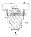
- Fig. 3 shows an example of a Druckmeßaufsacrificings with a pressure sensor according to the invention. It is here as an example of in Fig. 1 illustrated pressure sensor shown.
- the Druckmeßaufsacrificing has a metallic diaphragm seal 35, to which a housing 37 and connected to the housing 37 terminal housing 39 adjacent.
- the pressure transmitter 35 is substantially cylindrical and has at its end a liquid-filled chamber 41, which is closed by a metallic separation membrane 43.
- the pressure transmitter 35 and the separation membrane 43 are preferably made of a high quality and corrosion resistant Stainless steel. In operation, the pressure to be measured p acts on the separation membrane 43, which in Fig. 3 indicated by an arrow.
- the housing 37 is cylindrical and is located with an annular base on an annular separation membrane-facing away from end face of the diaphragm seal 35.
- Housing 37 and diaphragm seal 35 are either a single component or they are connected together by a compound 45 made of an inorganic material.
- the ceramic measuring cell 1 is arranged in the housing 37.
- the ceramic measuring cell 1 is fixed in the housing 37 by means of a connection 47 made of an inorganic material.
- the ceramic measuring cell 1 and the housing 37 are arranged cylindrical and coaxial with each other, so that the housing 37 surrounds the measuring cell 1.
- the connection 47 is preferably arranged in a ring-cylindrical gap between the housing 37 and the main body 3. This ensures that the sensitive measuring diaphragm 3 remains substantially free of stress.
- the housing 37 is preferably made of a material having a thermal expansion coefficient which is approximately equal to the thermal expansion coefficient of the ceramic of the measuring cell 1. If e.g. If a measuring cell made of an aluminum oxide is used, e.g. Nickel-iron-cobalt alloys, as e.g. commercially available under the product names Vacon or Kovar, suitable materials for the housing 37. Alternatively, however, the housing 37 may also be made of a ceramic, e.g. consist of an aluminum oxide. Such a suitable choice of material ensures that only very small forces are exerted by the housing 37 on the measuring cell 1, even with strong temperature fluctuations.
- connection between the housing 37 and the pressure transducer 35 for example, a weld and the connection 47, a metallic joint, for example with an active brazing, be.
- a metallic joint for example with an active brazing
- both connections 47 can be metallic joints, for example with an active hard solder.
- the pressure transmitter 35 has a through hole 49, one end of which opens into the chamber 41 and the other end opens into a bounded by the housing 37 and the measuring cell 1 chamber 51.
- the chamber 41, the bore 49 and the chamber 51, as well as an interior of the housing 37 facing the pressure transmitter 35 in front of the measuring cell 1 are provided with a liquid which is as incompressible as possible, e.g. a silicone oil, filled.
- a pressure acting on the separation membrane 43 pressure p is transmitted through the liquid to the measuring diaphragm 5, and it is detected by the relative pressure to be measured deflection of the measuring diaphragm 5 of the previously described capacitive electromechanical transducer and converted by the sensor electronics 13 into an electrical measurement.
- a further electronics may be arranged, which further processes the measured variables provided by the sensor electronics 13 via the connecting lines 17 and, for example, outputs a desired output in a particular application.
- Particularly frequently used output signals are e.g. Signal currents whose current changes as a function of the current measured value or digital signals which are coupled to a bus line via a bus interface.
- the pressure transmitter 35 has at its measuring cell end facing away from an external thread 53, by means of which the Druckmeßaufillon is front-flush screwed to a measuring location in a corresponding opening.
- the pressure transmitter 35 thus serves simultaneously as a process connection.
- the diaphragm seal 35 Above the external thread 53, the diaphragm seal 35 has an annular shoulder surface, in which a circumferential groove 55 for receiving a, in Fig. 3 Process seal, not shown, is provided.
- the in Fig. 3 illustrated Druckmeßaufsacrificing has the advantage that all with a medium whose pressure is to be measured in contact parts, ie the separation membrane 43 and all other with a medium whose pressure is to be measured p, when measuring coming into contact components, here only the external thread 53, metallic.
- the pressure transducer itself has no seals made of organic materials. It is only a single seal, namely the process seal, required, and this is interchangeable at any time.
- Metal is used in the food industry in particular, because metal is very easy to clean. Likewise, it is in the food industry for reasons of hygiene advantageous if as little as possible seals made of organic materials are necessary, and these are interchangeable at any time.
- FIGS. 4 and 5 are the ones in the Figures 1 and 2 illustrated pressure sensors in conjunction with a common in the food industry process connection 57 shown.
- the pressure sensors are clamped in a substantially cylindrical housing 58, the end in the process-facing direction has a shoulder 59 on which the measuring diaphragm 5 with the outer pressure-insensitive edge with the interposition of a seal 61, e.g. an O-ring, rests.
- a seal 61 e.g. an O-ring
- the housing 58 with the in the FIGS. 4 and 5 provided only schematically illustrated process connection 57, which is an integral part of the housing 58.
- the illustrated process connection 57 is a standard connection defined in international standard ISO 2852. This connection is known in metrology under the trade name 'Triclamp'. Other types of attachment are also applicable.
- a ring cylinder 63 At the in Fig. 4 illustrated embodiment is located on the radially outwardly extending edge 21 of the cap 19, a ring cylinder 63. It is a threaded ring 65 is provided, which is screwed from the process-side facing into the housing 58 against the annular cylinder 63 and presses the pressure measuring cell 1 against the seal 61 and the shoulder 59.
- the threaded ring 65 is made of metal, for example of a stainless steel.
- the ring cylinder 63 is preferably made of a plastic and serves to protect the cap 19 when screwing the threaded ring 65 and to compensate for stresses caused by different thermal expansions of the pressure measuring cell 1, the Housing 58 and the threaded ring 65 may arise. He also causes an insulation of the cap 19 relative to the housing 58th
- the pressure measuring cell 1 is also clamped by means of a screwed into the housing 58 threaded ring in the housing 58.
- the cap 27 is surrounded by a sleeve 67 which surrounds a circular disk-shaped end face of the cap 27 facing the shoulder 59, a cylindrical lateral surface facing the housing 58 and a circular-disk-shaped end face of the cap 27 facing away from the shoulder 59.
- the sleeve 67 is preferably made of a plastic and then causes an insulation of the pressure measuring cell 1 relative to the housing 58.
- the cap 27 consists of an insulator, eg of ceramic
- the sleeve 67 preferably consists of a metal and then causes an electrical shielding of the pressure measuring cell 1 against external electrical influences.
Description
- Die Erfindung betrifft einen Drucksensor.
- In der Druckmeßtechnik werden z.B. Absolut- und Relativdrucksensoren eingesetzt. Bei Absolutdrucksensoren wird ein zu messender Druck absolut, d.h. als Druckunterschied gegenüber einem Vakuum erfaßt. Mit einem Relativdrucksensor wird ein zu messender Druck in Form eines Druckunterschiedes gegenüber einem Referenzdruck aufgenommen. Der Referenzdruck ist ein Umgebungsdruck der dort herrscht, wo sich der Sensor befindet. Bei den meisten Anwendungen ist dies der Atmosphärendruck am Einsatzort.
- Druckmeßgeräte werden in einer Vielzahl von Industriezweigen eingesetzt, z.B. in der Chemie und in der Lebensmittelindustrie. In diesen Industrien sind häufig große Anlagen vorhanden in denen zur Erfassung, Steuerung, Regelung und/oder Automatisierung eines in der Anlage ablaufenden Prozesses an mehreren Stellen Drücke zu messen sind. Dabei kommen eine Vielzahl von Drucksensoren z.B. mit unterschiedlichen Meßbereichen zum Einsatz.
- Druckmeßgeräte sind häufig Feuchtigkeit ausgesetzt. Dies ist z.B. der Fall, wenn sie an Orten mit andauernder hoher Luftfeuchtigkeit, z.B. in den Tropen, eingesetzt werden, wenn in der Lebensmittelindustrie Behälter mit heißem Wasser gereinigt und anschließend mit kaltem Wasser gespült werden oder wenn der Druck eines kalten Mediums gemessen wird und sich aufgrund einer höheren Umgebungstemperatur Kondensat bildet.
- Drucksensoren weisen üblicherweise eine Meßzelle und eine mit der Meßzelle verbundene Sensorelektronik auf. (siehe
EP 0570624 A2 undUS 5051937 ). Die Meßzelle umfaßt einen elektromechanischen Wandler, der eine Reaktion eines druckempfindlichen Elementes in ein elektrisches Signal umwandelt, das über die Sensorelektronik aufgenommen und einer weiteren Auswertung und/oder Verarbeitung zugänglich ist. Die Sensorelektronik muß daher für einen Anschluß derselben, z.B. an eine Meßgerätelektronik oder eine Versorungs- und/oder Signalauswerteeinheit, zugänglich sein. Gerade die Sensorelektronik und deren elektrische Anschlüsse sind aber besonders empfindlich gegenüber Feuchtigkeit und gegenüber mechanischen Belastungen. - Es ist eine Aufgabe der Erfindung, einen Drucksensor mit einer Meßzelle und einer mit der Meßzelle verbundenen Sensorelektronik anzugeben, bei dem die Sensorelektronik und deren elektrische Anschlüsse vor äußeren Einflüssen geschützt sind.
- Hierzu besteht die Erfindung in einem Drucksensor gemäß dem Anspruch 1.
- Die auf einer Rückseite der Meßzelle angeordnete Sensorelektronik kann auf verschiedene Art und Weise positioniert sein. Einerseits kann die Sensorelektronik unmittelbar an einer Rückseite der Meßzelle und andererseits von der Rückseite abgesetzt montiert sein. Für die abgesetzte Montage kann die Sensorelektronik beispielsweise an einem geeigneten Abstandhalter befestigt sein, der an der Rückseite der Meßzelle angebracht ist. Ein solcher Abstandhalter kann u.a. der thermischen Entkopplung der Sensorelektronik von der Meßzelle dienen. Als Abstandhalter kann u.a. eine Leiterplatte eingesetzt werden, die sich im wesentlichen senkrecht zur Oberfläche der Rückseite der Meßzelle erstreckt.
- Gemäß einer Ausgestaltung der Erfindung ist eine Durchführung für ein Röhrchen in der Kappe vorgesehen, und ein Referenzdruck, auf den der zu messende Druck zu beziehen ist, ist im Betrieb durch das Röhrchen hindurch zu der Meßzelle geführt.
- Gemäß einer ersten Ausgestaltung ist die Kappe mit deren offenem Ende auf einem äußeren Rand der Rückseite der Meßzelle befestigt.
- Gemäß einer zweiten Ausgestaltung ist die Kappe über die Meßzelle gestülpt und an deren offenem Ende mit einer geschlossenen Teilfläche einer von der Vorderseite zur Rückseite der Meßzelle führenden Mantelfläche verbunden.
- Gemäß einer Ausgestaltung besteht die Meßzelle aus Keramik, die Kappe besteht aus einem Metall, und die Meßzelle und die Kappe sind mittels einer Fügung hermetisch dicht miteinander verbunden.
- Gemäß einer Ausgestaltung besteht die Meßzelle aus Aluminiumoxid, die Kappe besteht aus einer Nickel-Eisen-Kobalt-Legierung, und die Fügung besteht aus einem Aktivhartlot.
- Gemäß einer anderen Ausgestaltung besteht die Meßzelle aus Keramik, die Kappe besteht aus Keramik, und die Meßzelle und die Kappe sind mittels einer Fügung aus einem Aktivhartlot hermetisch dicht miteinander verbunden.
- Die Kappe bietet einen effektiven Schutz der Meßzelle vor Feuchtigkeit und vor mechanischen und chemischen Einflüssen aus der Umgebung.
- Die Erfindung und weitere Vorteile werden nun anhand der Figuren der Zeichnung, in denen zwei Ausführungsbeispiele dargestellt sind, näher erläutert. Gleiche Elemente sind in den Figuren mit den gleichen Bezugszeichen versehen.
-
Fig. 1 zeigt einen Schnitt durch einen kapazitiven keramischen Drucksensor, bei dem eine Kappe auf der Rückseite der Meßzelle vorgesehen ist, in der die Sensorelektronik eingeschlossen ist; -
Fig. 2 zeigt einen Schnitt durch einen kapazitiven keramischen Drucksensor, bei dem eine Kappe die Meßzelle bis auf das druckempfindliche Element einschließt; -
Fig. 3 zeigt einen Schnitt durch ein Druckmeßgerät, in das die inFig. 1 dargestellte Druckmeßzelle eingebaut ist; -
Fig. 4 zeigt einen Schnitt durch ein Gehäuse mit einem Prozeßanschluß, in das die inFig. 1 dargestellte Druckmeßzelle eingebaut ist; und -
Fig. 5 zeigt einen Schnitt durch ein Gehäuse mit einem Prozeßanschluß, in das die inFig. 2 dargestellte Druckmeßzelle eingebaut ist. - In
Fig. 1 ist ein Schnitt durch einen erfindungsgemäßen Drucksensor dargestellt. Er weist eine Meßzelle 1 auf.
Die Meßzelle 1 ist in dem gezeigten Ausführungsbeispiel eine Relativdruckmeßzelle. An einer Vorderseite der Meßzelle 1 ist ein druckempfindliches Element angeordnet, auf das im Betrieb ein zu messender Druck einwirkt. - Die Meßzelle 1 weist einen Grundkörper 3 und eine Meßmembran 5 auf. Der Grundkörper 3 besteht z.B. aus Keramik. Die Meßmembran 5 kann ebenfalls aus Keramik bestehen oder z.B. aus Saphir. Die Meßmembran 5 und der Grundkörper 3 sind an deren Rand unter Bildung einer Meßkammer mittels einer Fügestelle 7 druckdicht und gasdicht miteinander verbunden. Die Meßmembran 5 bildet das druckempfindliche Element. Ein auf sie einwirkender Druck bewirkt eine Auslenkung der Meßmembran 5 aus deren Ruhelage.
- Auf einer Innenseite der Meßmembran 5 ist eine Elektrode 9 und auf einer gegenüberliegenden Innenseite des Grundkörpers 3 ist mindestens eine Gegenelektrode 11 angeordnet. Die Elektrode 9 der Meßmembran 5 ist durch die Fügestelle 7 hindurch elektrisch kontaktiert und außerhalb z.B. mit Masse verbunden. Die Gegenelektrode 11 des Grundkörpers 3 ist durch den Grundkörper 3 hindurch zu dessen Außenseite hin elektrisch kontaktiert und führt zu einer auf einer Rückseite der Meßzelle auf dem Grundkörper 3 angeordneten Sensorelektronik 13. Elektrode 9 und Gegenelektrode 11 bilden einen Kondensator und die Sensorelektronik 13 formt die Kapazitätsänderungen des Kondensators z.B. in eine sich entsprechend ändernde elektrische Spannung um.
- Der Grundkörper 3 weist eine durchgehende Bohrung auf, in die ein Röhrchen 15 eingeführt ist, das in die Meßkammer hinein führt. Über das Röhrchen 15 wirkt z.B. ein in der Umgebung der Meßzelle 1 herrschender Referenzdruck pR, auf den der zu messende Druck zu beziehen ist, auf eine Innenseite der Meßmembran 5 ein. Dies ist in
Fig. 1 durch einen Pfeil symbolisch dargestellt - Im Betrieb wirkt auf eine Außenseite der Meßmembran 5 ein zu messender Druck p ein. Dies ist in
Fig. 1 ebenfalls durch einen Pfeil symbolisch dargestellt. - Der Druck p und der Referenzdruck pR bewirken eine vom zu messenden Relativdruck abhängige Auslenkung der Meßmembran 5 die von dem zuvor beschriebenen kapazitiven elektromechanischen Wandler erfaßt und von der Sensorelektronik 13 in eine elektrische Meßgröße umgewandelt wird. Die Meßgröße steht über Anschlußleitungen 17 einer weiteren Verarbeitung und/oder Auswertung zur Verfügung.
- Anstatt der beschriebenen kapazitiven keramischen Meßzelle kann z.B. auch eine piezoresistive Meßzelle verwendet werden. Bei diesen Arten von Meßzellen weist der Wandler auf der Meßmembran aufgebrachte Dehnmeßstreifen auf. Die Meßkammer kann auch bei diesen Meßzellen durch einen Grundkörper und die Meßmembran selber gebildet sein. Die Meßmembran ist dann mit deren äußerem Rand auf dem Grundkörper befestigt.
- Der Drucksensor weist eine fest mit der Meßzelle verbundenen Kappe 19 auf, die die Sensorelektronik 13 umschließt. Die Kappe 19 ist topfförmig und sie ist mit deren offenem Ende auf einem äußeren Rand der Rückseite der Meßzelle 1 befestigt. Bei dem in
Fig. 1 dargestellten Ausführungsbeispiel weist die Kappe 19 an deren offenem Ende einen sich radial nach außen erstreckenden Rand 21 auf, der parallel zu der membran-abgewandten Rückseite des Grundkörpers 3 verläuft. - Die Meßzelle 1 besteht aus Keramik, vorzugsweise aus Aluminiumoxid. Die Kappe 19 besteht aus einem Metall.
Wird eine Meßzelle 1 aus einem Aluminiumoxid verwendet, so sind z.B. Nickel-Eisen-Kobalt-Legierungen, wie sie z.B. unter den Produktnamen Vacon oder Kovar im Handel erhältlich sind, besonders geeignete Werkstoffe für die Kappe 19, da diese Werkstoffe einen thermischen Ausdehnungskoeffiezienten aufweisen, der dem thermischen Ausdehnungskoeffizienten von Aluminiumoxid sehr ähnlich ist. Die Meßzelle 1 und die Kappe 19 sind mittels einer Fügung 23, vorzugsweise aus einem Aktivhartlot, mechanisch fest und hermetisch dicht miteinander verbunden. Alternativ können die Meßzelle 1 und die Kappe 19 auch auf andere Weise z.B. unter Zwischenfügung einer Dichtung dicht und fest miteinander verbunden sein. - Die Kappe 19 weist mindestens eine Durchführung 25, z.B. in Öffnungen in der Kappe 19 eingeschmolzene Glasdurchführungen, auf, durch die an die Sensorelektronik 13 angeschlossene elektrische Anschlußleitungen 17 hindurch geführt sind. Anstelle von Glasdurchführungen können auch andere Durchführungen, z.B. Durchführungen mit Hartverguß oder Manschetten aus anderen Dichtungswerkstoffen eingesetzt werden. Bei dem in
Fig. 1 dargestellten Ausführungsbeispiel sind zwei Durchführungen 25 symbolisch dargestellt. Zusätzlich ist bei dem inFig. 1 dargestellten Ausführungsbeispiel eine weitere Durchführung 26, z.B. ebenfalls eine Glasdurchführung, für das Röhrchen 15 in der Kappe 19 vorgesehen. Durch das Röhrchen 15 hindurch ist der Referenzdruck pR, auf den der zu messende Druck p zu beziehen ist, im Betrieb zu der Meßzelle geführt. Je nach Aufbau der Meßzelle kann das Röhchen 15 natürlich auch weiter von der Sensorelektronik 13 entfernt sein. In dem Fall kann das Röhrchen 15 seitlich an der Kappe 19 vorbei geführt sein. Eine zusätzliche Durchführung entfällt in dem Fall natürlich. - Natürlich kann der erfindungsgemäße Drucksensor auch als ein Absolutdrucksensor ausgebildet sein. Dann ist die Meßkammer der Meßzelle 1 evakuiert und die Bohrung durch den Grundkörper 3, das Röhrchen 15 und die Durchführung 26 entfallen.
- In
Fig. 2 ist ein weiteres Ausführungsbeispiel eines erfindungsgemäßen Drucksensors dargestellt. Die Meßzelle 1 ist identisch zu der inFig. 1 dargestellten Meßzelle 1. - Auch das in
Fig. 2 dargestellte Ausführungsbeispiel weist eine Kappe 27 auf, die die Sensorelektronik 13 umschließt. Sie weist einen Zylinder 29 und eine ein Ende des Zylinders 29 verschließende Scheibe 31 auf. Die Kappe 27 ist über die Meßzelle 1 gestülpt und an deren offenem Ende mit einer geschlossenen Teilfläche 33 einer von der Vorderseite zur Rückseite der Meßzelle 1 führenden Mantelfläche verbunden. - Die Scheibe 31 weist drei Öffnungen auf in die die Durchführungen 25 für die Anschlußleitungen 17 und die Durchführung 26 für das Röhrchen 15 eingebracht sind.
- Die Meßzelle 1 besteht auch bei dem in
Fig. 2 dargestellten Ausführungsbeispiel aus Keramik, vorzugsweise aus Aluminiumoxid. - Die Kappe 27 besteht aus einem Metall oder aus Keramik, vorzugsweise aus Aluminiumoxid. Wird eine Meßzelle 1 aus einem Aluminiumoxid verwendet, so sind z.B. Nickel-Eisen-Kobalt-Legierungen, wie sie z.B. unter den Produktnamen Vacon oder Kovar im Handel erhältlich sind, besonders geeignete Werkstoffe für die Kappe 27, da diese Werkstoffe einen thermischen Ausdehnungskoeffiezienten aufweisen, der dem thermischen Ausdehnungskoeffizienten von Aluminiumoxid sehr ähnlich ist. Besteht die Kappe 27 aus Keramik, so wird vorzugsweise für Kappe 27 und Meßzelle 1 der gleiche Werkstoff verwendet.
- Die Meßzelle 1 und die Kappe 27 sind mittels einer Fügung 34, vorzugsweise aus einem Aktivhartlot, mechanisch fest und hermetisch dicht miteinander verbunden.
- Besteht die Kappe 19 bzw. 27 aus einem Metall, so bietet dies den Vorteil, daß im Inneren der Kappe 19 bzw. 27 definierte elektrische Bedingungen bestehen, die sich durch den Einbau der Druckmeßzelle nicht mehr verändern. Dies bedeutet, daß die elektrischen Verhältnisse wie sie bei der Kalibration der Druckmeßzelle bestehen sich nicht mehr verändern. Es kommen z.B. keine nachteiligen Einflüsse durch Streukapazitäten zu Gehäuseteilen zum tragen. Außerdem bildet eine metallische Kappe 19, 27 quasi einen Faraday-Käfig und bietet somit einen gewissen Schutz für die elektronische Schaltung 13 vor elektromagnetischen Störungen.
-
Fig. 3 zeigt ein Beispiel eines Druckmeßaufnehmers mit einem erfindungsgemäßen Drucksensor. Es ist hier als Beispiel der inFig. 1 dargestellte Drucksensor dargestellt. - Der Druckmeßaufnehmer weist einen metallischen Druckmittler 35 auf, an den ein Gehäuse 37 und ein mit dem Gehäuse 37 verbundenes Anschlußgehäuse 39 angrenzen.
- Der Druckmittler 35 ist im wesentlichen zylindrisch und weist endseitig eine mit einer Flüssigkeit gefüllte Kammer 41 auf, die von einer metallischen Trennmembran 43 verschlossen ist. Der Druckmittler 35 und die Trennmembran 43 bestehen vorzugsweise aus einem hochwertigen und korrosionsbeständigen Edelstahl. Im Betrieb wirkt auf die Trennmembran 43 der zu messende Druck p ein, der in
Fig. 3 durch einen Pfeil angedeutet ist. - Das Gehäuse 37 ist zylindrisch und liegt mit einer kreisringförmigen Grundfläche auf einer kreisringförmigen trennmembran-abgewandten Stirnfläche des Druckmittlers 35 auf. Gehäuse 37 und Druckmittler 35 sind entweder ein einziges Bauteil oder sie sind miteinander durch eine Verbindung 45 aus einem anorganischen Material verbunden.
- In dem Gehäuse 37 ist die keramische Meßzelle 1 angeordnet.
Die keramische Meßzelle 1 ist in dem Gehäuse 37 mittels einer Verbindung 47 aus einem anorganischen Material befestigt. In dem gezeigten Ausführungsbeispiel sind die keramische Meßzelle 1 und das Gehäuse 37 zylindrisch und koaxial zueinander angeordnet, so daß das Gehäuse 37 die Meßzelle 1 umgibt. Die Verbindung 47 ist vorzugsweise in einem ringzylindrischen Spalt zwischen dem Gehäuse 37 und dem Grundkörper 3 angeordnet. Hierdurch wird erreicht, daß die empfindliche Meßmembran 3 im wesentlichen einspannungsfrei bleibt. - Das Gehäuse 37 besteht vorzugsweise aus einem Material, das einen thermischen Ausdehnungskoeffizienten aufweist, der ungefähr gleich dem thermischen Ausdehnungskoeffizienten der Keramik der Meßzelle 1 ist. Wird z.B. eine Meßzelle aus einem Aluminiumoxid verwendet, so sind z.B. Nickel-Eisen-Kobalt-Legierungen, wie sie z.B. unter den Produktnamen Vacon oder Kovar im Handel erhältlich sind, geeignete Werkstoffe für das Gehäuse 37. Alternativ kann das Gehäuse 37 aber auch ebenfalls aus einer Keramik, z.B. einem Aluminiumoxid bestehen. Durch eine solche geeignete Materialwahl wird erreicht, daß auch bei starken Temperaturschwankungen nur sehr geringe Kräfte vom Gehäuse 37 auf die Meßzelle 1 ausgeübt werden.
- Bei einem metallischen Gehäuse 37 kann die Verbindung zwischen dem Gehäuse 37 und dem Druckaufnehmer 35 z.B. eine Schweißung und die Verbindung 47 eine metallische Fügung, z.B. mit einem Aktivhartlot, sein. Bei einem Gehäuse 37 aus Keramik können beide Verbindungen 47 metallische Fügungen, z.B. mit einem Aktivhartlot sein.
- Der Druckmittler 35 weist eine durchgehende Bohrung 49 auf, deren eines Ende in die Kammer 41 mündet und deren anderes Ende in einer durch das Gehäuse 37 und die Meßzelle 1 begrenzten Kammer 51 mündet. Die Kammer 41, die Bohrung 49 und die Kammer 51, sowie ein vor der Meßzelle 1 dem Druckmittler 35 zugewandter Innenraum des Gehäuses 37 sind mit einer möglichst inkompressiblen Flüssigkeit, z.B. einem Silikonöl, gefüllt.
- Ein auf die Trennmembran 43 einwirkender Druck p wird durch die Flüssigkeit auf die Meßmembran 5 übertragen, und es wird eine vom zu messenden Relativdruck abhängige Auslenkung der Meßmembran 5 von dem zuvor beschriebenen kapazitiven elektromechanischen Wandler erfaßt und von der Sensorelektronik 13 in eine elektrische Meßgröße umgewandelt.
- In dem Anschlußgehäuse 39 kann z.B. eine weiterführende Elektronik angeordnet sein, die die von der Sensor-elektronik 13 über die Anschlußleitungen 17 zur Verfügung gestellten Meßgrößen weiter verarbeitet und z.B. ein in einer speziellen Anwendung gewünschtes Ausgangssignal abgibt. Besonders häufig verwendete Ausgangssignale sind z.B. Signalströme, deren Stromstärke sich in Abhängigkeit vom aktuellen Meßwert ändert oder digitale Signale, die über eine Busanschaltung auf eine Busleitung eingekoppelt werden.
- Der Druckmittler 35 weist an dessen meßzellen-abgewandten Ende ein Außengewinde 53 auf, mittels dessen der Druckmeßaufnehmer an einem Meßort in eine entsprechende Öffnung frontbündig einschraubbar ist. Der Druckmittler 35 dient somit gleichzeitig als Prozeßanschluß. Oberhalb des Außengewindes 53 weist der Druckmittler 35 eine ringförmige Absatzfläche auf, in der eine umlaufende Nut 55 zur Aufnahme einer, in
Fig. 3 nicht dargestellten Prozeßdichtung, vorgesehen ist. - Der in
Fig. 3 dargestellte Druckmeßaufnehmer bietet den Vorteil, daß alle mit einem Medium dessen Druck gemessen werden soll in Kontakt tretenden Teile, also die Trennmembran 43 und alle weiteren mit einem Medium, dessen Druck p zu messen ist, beim Messen in Kontakt kommenden Bauteile, hier lediglich das Außengewinde 53, metallisch sind. Der Druckaufnehmer selber weist keinerlei Dichtungen aus organischen Materialien aufweist. Es ist lediglich eine einzige Dichtung, nämlich die Prozeßdichtung, erforderlich, und diese ist jederzeit austauschbar. - Metall wird insb. in der Lebensmittelindustrie sehr gerne verwendet, da Metall sehr gut zu reinigen ist. Ebenso ist es in der Lebensmittelindustrie aus hygienischen Gründen von Vorteil, wenn möglichst wenig Dichtungen aus organischen Materialien notwendig sind, und diese jederzeit austauschbar sind.
- Natürlich können die erfindungsgemäßen Drucksensoren auch in anderer Weise als in
Fig. 3 dargestellt eingesetzt werden. Sie können z.B. einfach derart in ein Gehäuse eingespannt werden, daß das druckempfindliche Element von außen direkt zugänglich ist. - In den
Figuren 4 und 5 sind die in denFiguren 1 und 2 dargestellten Drucksensoren in Verbindung mit einem in der Lebensmittelindustrie üblichen Prozeßanschluß 57 dargestellt. - Die Drucksensoren sind in ein im wesentlichen zylindrisches Gehäuse 58 eingespannt, das endseitig in prozeß-zugewandter Richtung eine Schulter 59 aufweist, auf der die Meßmembran 5 mit deren äußerem druckunempfindlichen Rand unter Zwischenfügung einer Dichtung 61, z.B. eines O-Rings, aufliegt.
- Zur Befestigung an einem Meßort ist das Gehäuse 58 mit dem in den
Figuren 4 und 5 lediglich schematisch dargestellten Prozeßanschluß 57 versehen, der integraler Bestandteil des Gehäuses 58 ist. Bei dem dargestellten Prozeßanschluß 57 handelt es sich um einen Standardanschluß, der in der internationalen Norm ISO 2852 definiert ist. Dieser Anschluß ist in der Meßtechnik unter dem Handelsnamen 'Triclamp' bekannt. Andere Arten der Befestigung sind ebenfalls einsetzbar. - Bei dem in
Fig. 4 dargestellten Ausführungsbeispiel liegt auf dem sich radial nach außen erstreckenden Rand 21 der Kappe 19 ein Ringzylinder 63 auf. Es ist ein Gewindering 65 vorgesehen, der von der prozeß-abgewandten Seite her in das Gehäuse 58 hinein gegen den Ringzylinder 63 geschraubt ist und die Druckmeßzelle 1 gegen die Dichtung 61 und die Schulter 59 preßt. Der Gewindering 65 besteht aus Metall, z.B. aus einem Edelstahl. Der Ringzylinder 63 besteht vorzugsweise aus einem Kunststoff und dient zum Schutz der Kappe 19 beim Einschrauben des Gewinderings 65 und zum Ausgleich von Spannungen, die durch unterschiedliche thermische Ausdehnungen der Druckmeßzelle 1, des Gehäuses 58 und des Gewinderings 65 entstehen können. Auch bewirkt er eine Isolation der Kappe 19 gegenüber dem Gehäuse 58. - Bei dem in
Fig. 5 dargestellten Ausführungsbeispiel ist die Druckmeßzelle 1 ebenfalls mittels eines in das Gehäuse 58 eingeschraubten Gewinderings in das Gehäuse 58 eingespannt. - Die Kappe 27 ist von einer Hülse 67 umgeben, die eine der Schulter 59 zugewandte kreisscheibenförmige Stirnfläche der Kappe 27, eine dem Gehäuse 58 zugewandten zylindrischen Mantelfläche und eine von der Schulter 59 abgewandte kreisscheibenförmige Stirnfläche der Kappe 27 umgibt.
Besteht die Kappe 27 aus einem Metall, so besteht die Hülse 67 vorzugsweise aus einem Kunststoff und bewirkt dann eine Isolation der Druckmeßzelle 1 gegenüber dem Gehäuse 58. Besteht die Kappe 27 dagegen aus einem Isolator, z.B. aus Keramik, so besteht die Hülse 67 vorzugsweise aus einem Metall und bewirkt dann eine elektrische Abschirmung der Druckmeßzelle 1 gegenüber äußeren elektrischen Einflüssen.
Claims (8)
- Drucksensor mit- einer Meßzelle (1), die aus Keramik besteht,- einem an einer Vorderseite der Meßzelle (1) angeordneten druckempfindlichen Element, auf das im Betrieb ein zu messender Druck (p) einwirkt,- einer auf einer Rückseite der Meßzelle (1) angeordneten Sensorelektronik (13), und- einer mit der Meßzelle (1) verbundenen Kappe (19, 27) die aus Metall oder aus Keramik besteht,-- die die Sensorelektronik (13) umschließt, und-- die mindestens eine Durchführung (25) aufweist,--- durch die an die Sensorelektronik (13) angeschlossene Anschlußleitungen (17) hindurch geführt sind, dadurch gekennzeichnet, daß- die Meßzelle (1) und die Kappe (19, 27) mittels einer Fügung hermetisch dicht miteinander verbunden sind.
- Drucksensor nach Anspruch 1, bei dem eine Durchführung (26) für ein Röhrchen (15) in der Kappe (19, 27) vorgesehen ist, und bei dem ein Referenzdruck (pR), auf den der zu messende Druck (p) zu beziehen ist, im Betrieb durch das Röhrchen (15) hindurch zu der Meßzelle (1) geführt ist.
- Drucksensor nach Anspruch 1, bei dem die Kappe (19) mit deren offenem Ende auf einem äußeren Rand der Rückseite der Meßzelle (1) befestigt ist.
- Drucksensor nach Anspruch 1, bei dem die Kappe (27) über die Meßzelle (1) gestülpt ist und an deren offenem Ende mit einer geschlossenen Teilfläche einer von der Vorderseite zur Rückseite der Meßzelle (1) führenden Mantelfläche verbunden ist.
- Drucksensor nach Anspruch 1, bei dem- die Meßzelle (1) aus Aluminiumoxid besteht,- die Kappe (19, 27) aus einer Nickel-Eisen-Kobalt-Legierung besteht, und- die Fügung aus einem Aktivhartlot besteht.
- Drucksensor nach Anspruch 1, bei dem- die Kappe (27) aus Keramik besteht, und- die Fügung aus einem Aktivhartlot hermetisch besteht.
- Drucksensor nach einem der vorhergenenden Ansprüche, bei dem die Sensorelektronik (13) unmittelbar an der Rückseite der Druckmeßzelle (1) angeordnet ist.
- Drucksensor nach einem der Ansprüche 1 bis 6, bei dem die Sensorelektronik (13) beabstandet zur Rückseite der Druckmeßzelle (1) montiert ist.
Applications Claiming Priority (3)
| Application Number | Priority Date | Filing Date | Title |
|---|---|---|---|
| DE10135568 | 2001-07-20 | ||
| DE10135568A DE10135568A1 (de) | 2001-07-20 | 2001-07-20 | Drucksensor |
| PCT/EP2002/007976 WO2003014688A1 (de) | 2001-07-20 | 2002-07-18 | Drucksensor |
Publications (2)
| Publication Number | Publication Date |
|---|---|
| EP1409979A1 EP1409979A1 (de) | 2004-04-21 |
| EP1409979B1 true EP1409979B1 (de) | 2014-06-11 |
Family
ID=7692618
Family Applications (1)
| Application Number | Title | Priority Date | Filing Date |
|---|---|---|---|
| EP02762372.7A Expired - Lifetime EP1409979B1 (de) | 2001-07-20 | 2002-07-18 | Drucksensor |
Country Status (4)
| Country | Link |
|---|---|
| US (1) | US7152477B2 (de) |
| EP (1) | EP1409979B1 (de) |
| DE (1) | DE10135568A1 (de) |
| WO (1) | WO2003014688A1 (de) |
Families Citing this family (30)
| Publication number | Priority date | Publication date | Assignee | Title |
|---|---|---|---|---|
| CN1726385B (zh) * | 2002-12-12 | 2010-04-21 | 丹福斯有限公司 | 压力传感器 |
| DE10308820B4 (de) * | 2003-02-27 | 2006-10-12 | Ifm Electronic Gmbh | Sensor, Meßzelle zur Verwendung in einem Sensor und Verfahren zur Herstellung einer Meßzelle |
| DE10326975A1 (de) | 2003-06-12 | 2005-01-20 | Endress + Hauser Gmbh + Co. Kg | Drucksensor mit Feuchteschutz |
| US7353711B2 (en) * | 2003-08-11 | 2008-04-08 | Analog Devices, Inc. | Capacitive sensor |
| US8870787B2 (en) | 2003-09-16 | 2014-10-28 | Cardiomems, Inc. | Ventricular shunt system and method |
| CA2539261C (en) | 2003-09-16 | 2011-05-17 | Cardiomems, Inc. | Implantable wireless sensor |
| US8026729B2 (en) | 2003-09-16 | 2011-09-27 | Cardiomems, Inc. | System and apparatus for in-vivo assessment of relative position of an implant |
| JP4075776B2 (ja) * | 2003-11-13 | 2008-04-16 | 株式会社デンソー | 物理量センサおよび圧力センサ |
| DE102004019389A1 (de) * | 2004-04-19 | 2005-11-03 | Endress + Hauser Gmbh + Co. Kg | Druckaufnehmer mit austauschbarem Prozessanschluss |
| DE102004031582A1 (de) * | 2004-06-29 | 2006-02-09 | Endress + Hauser Gmbh + Co. Kg | Duckaufnehmer |
| DE102004052950A1 (de) * | 2004-10-29 | 2006-05-04 | Endress + Hauser Gmbh + Co. Kg | Druckaufnehmer mit hydraulischer Druckübertragung |
| US7647836B2 (en) | 2005-02-10 | 2010-01-19 | Cardiomems, Inc. | Hermetic chamber with electrical feedthroughs |
| US7662653B2 (en) * | 2005-02-10 | 2010-02-16 | Cardiomems, Inc. | Method of manufacturing a hermetic chamber with electrical feedthroughs |
| AU2006262287A1 (en) | 2005-06-21 | 2007-01-04 | Cardiomems, Inc. | Method of manufacturing implantable wireless sensor for in vivo pressure measurement |
| DE102005046331A1 (de) * | 2005-09-27 | 2007-03-29 | Endress + Hauser Flowtec Ag | Vorrichtung zur Bestimmung und/oder Überwachung einer Prozessgröße |
| WO2007061841A2 (en) * | 2005-11-18 | 2007-05-31 | Cardiomems, Inc. | Capacitor electrode formed on surface of integrated circuit chip |
| DE102006032493B3 (de) * | 2006-07-13 | 2008-04-10 | Siemens Ag | Verfahren zur Plausibilisierung eines Umgebungsdrucksensors für eine Brennkraftmaschine, Steuereinrichtung und Brennkraftmaschine |
| EP2312290B1 (de) * | 2009-10-16 | 2019-09-25 | First Sensor Mobility GmbH | Drucksensor und dessen Verwendung in einem Fluidtank |
| DE102011008171A1 (de) * | 2011-01-10 | 2012-07-12 | Continental Automotive Gmbh | Sensorvorrichtung |
| DE102011002596A1 (de) * | 2011-01-12 | 2012-07-12 | Robert Bosch Gmbh | Brennraumdrucksensor zur Erfassung eines Drucks in einem Brennraum einer Verbrennungskraftmaschine |
| DE102011005274B4 (de) | 2011-03-09 | 2020-09-10 | Endress+Hauser SE+Co. KG | Keramische Druckmesszelle |
| DE102013114608A1 (de) * | 2013-12-20 | 2015-07-09 | Endress + Hauser Gmbh + Co. Kg | Relativdrucksensor |
| US9648745B2 (en) | 2014-10-22 | 2017-05-09 | Honeywell International Inc. | Systems and methods for mounting the printed wiring assembly to the header assembly of a pressure sensor |
| US9702740B2 (en) * | 2015-04-17 | 2017-07-11 | Wika Alexander Wiegand Se & Co. Kg | Measuring instrument with connecting coupling |
| CN108700483B (zh) | 2016-02-25 | 2020-09-29 | 西铁城精密器件株式会社 | 压力检测装置以及压力检测系统 |
| JP6871721B2 (ja) | 2016-11-17 | 2021-05-12 | 株式会社堀場エステック | 圧力式流量計 |
| ES1217769Y (es) * | 2018-07-26 | 2018-12-13 | Cebi Electromechanical Components Spain S A | Medidor de presion para circuitos de fluidos |
| ES1218484Y (es) * | 2018-08-28 | 2018-12-27 | Cebi Electromechanical Components Spain S A | Dispositivo medidor de presion y temperatura de fluidos |
| JP7077210B2 (ja) * | 2018-11-22 | 2022-05-30 | シチズンファインデバイス株式会社 | 圧力検出装置、回路内蔵部材、圧力検出装置の製造方法 |
| DE102019104841A1 (de) | 2019-02-26 | 2020-08-27 | Endress+Hauser SE+Co. KG | Messgerät mit einem Sensorelement und einer Mess- und Betriebsschaltung |
Family Cites Families (13)
| Publication number | Priority date | Publication date | Assignee | Title |
|---|---|---|---|---|
| US4127840A (en) * | 1977-02-22 | 1978-11-28 | Conrac Corporation | Solid state force transducer |
| DE3447396A1 (de) * | 1984-12-24 | 1986-07-03 | Robert Bosch Gmbh, 7000 Stuttgart | Elektrischer druckgeber |
| DE3569824D1 (en) * | 1985-09-11 | 1989-06-01 | Kunz Manfred | Pressure sensor |
| US5051937A (en) | 1986-05-05 | 1991-09-24 | Texas Instruments Incorporated | Low cost high precision sensor |
| US5022270A (en) * | 1989-06-15 | 1991-06-11 | Rosemount Inc. | Extended measurement capability transmitter having shared overpressure protection means |
| US5343757A (en) | 1992-05-21 | 1994-09-06 | Fuji Koki Manufacturing Co., Ltd. | Pressure sensor |
| DE4244459C1 (de) * | 1992-12-23 | 1994-05-11 | Siemens Ag | Druckmeßumformer |
| JPH07198515A (ja) | 1993-12-29 | 1995-08-01 | Omron Corp | 圧力センサ |
| JPH1172400A (ja) | 1997-08-28 | 1999-03-16 | Matsushita Electric Works Ltd | 圧力検知装置 |
| EP1106982B1 (de) * | 1999-12-10 | 2005-02-09 | Endress + Hauser GmbH + Co. KG | Druckmessgerät |
| EP1126259B1 (de) * | 2000-02-15 | 2008-12-10 | Endress + Hauser GmbH + Co. KG | Drucksensor |
| EP1128172B1 (de) * | 2000-02-22 | 2011-04-06 | Endress + Hauser GmbH + Co. KG | Drucksensor |
| DE10134359A1 (de) * | 2001-07-14 | 2003-02-06 | Endress & Hauser Gmbh & Co Kg | Relativdruckmeßgerät |
-
2001
- 2001-07-20 DE DE10135568A patent/DE10135568A1/de not_active Withdrawn
-
2002
- 2002-07-18 WO PCT/EP2002/007976 patent/WO2003014688A1/de not_active Application Discontinuation
- 2002-07-18 US US10/481,881 patent/US7152477B2/en not_active Expired - Lifetime
- 2002-07-18 EP EP02762372.7A patent/EP1409979B1/de not_active Expired - Lifetime
Also Published As
| Publication number | Publication date |
|---|---|
| DE10135568A1 (de) | 2003-02-06 |
| US20050056097A1 (en) | 2005-03-17 |
| WO2003014688A1 (de) | 2003-02-20 |
| US7152477B2 (en) | 2006-12-26 |
| EP1409979A1 (de) | 2004-04-21 |
Similar Documents
| Publication | Publication Date | Title |
|---|---|---|
| EP1409979B1 (de) | Drucksensor | |
| EP1128172B1 (de) | Drucksensor | |
| EP1106982B1 (de) | Druckmessgerät | |
| EP2454574B1 (de) | Kapazitive keramische druckmesszelle und drucksensor mit einer solchen druckmesszelle | |
| EP0524550B1 (de) | Gasgefüllter Relativdrucksensor | |
| EP1126259B1 (de) | Drucksensor | |
| EP1327128B1 (de) | Druckmessanordnung | |
| EP0759547B1 (de) | Drucksensor | |
| DE4335588C2 (de) | Drucksensor | |
| EP3500832B1 (de) | Füllkörper zur reduktion eines volumens einer druckmesskammer | |
| EP2841899B1 (de) | Druckmessaufnehmer | |
| DE102009046692A1 (de) | Druck-Messeinrichtung | |
| EP1618362A1 (de) | Druckaufnehmer mit temperaturkompensation | |
| DE102014119396A1 (de) | Druckmesseinrichtung | |
| EP1065488B1 (de) | Relativdrucksensor | |
| EP1275950B1 (de) | Relativdruckmessgerät | |
| EP1631804A1 (de) | Drucksensor mit feuchteschutz | |
| WO2004090494A2 (de) | RELATIVDRUCKMEßUMFORMER | |
| EP1325294B1 (de) | Membran druckmessaufnehmer mit dichtung mit federring gegen verformung | |
| DE10133066B4 (de) | Druckmeßgerät | |
| WO2017050582A1 (de) | Druckmesseinrichtung | |
| DE10221219A1 (de) | Drucksensor | |
| DE102020132687A1 (de) | Druckmessaufnehmer | |
| DE102007037169A1 (de) | Drucksensor und Druckaufnehmer | |
| DE10134360A1 (de) | Drucksensor |
Legal Events
| Date | Code | Title | Description |
|---|---|---|---|
| PUAI | Public reference made under article 153(3) epc to a published international application that has entered the european phase |
Free format text: ORIGINAL CODE: 0009012 |
|
| 17P | Request for examination filed |
Effective date: 20031224 |
|
| AK | Designated contracting states |
Kind code of ref document: A1 Designated state(s): AT BE BG CH CY CZ DE DK EE ES FI FR GB GR IE IT LI LU MC NL PT SE SK TR |
|
| AX | Request for extension of the european patent |
Extension state: AL LT LV MK RO SI |
|
| 17Q | First examination report despatched |
Effective date: 20071116 |
|
| GRAP | Despatch of communication of intention to grant a patent |
Free format text: ORIGINAL CODE: EPIDOSNIGR1 |
|
| INTG | Intention to grant announced |
Effective date: 20140124 |
|
| GRAS | Grant fee paid |
Free format text: ORIGINAL CODE: EPIDOSNIGR3 |
|
| GRAA | (expected) grant |
Free format text: ORIGINAL CODE: 0009210 |
|
| AK | Designated contracting states |
Kind code of ref document: B1 Designated state(s): AT BE BG CH CY CZ DE DK EE ES FI FR GB GR IE IT LI LU MC NL PT SE SK TR |
|
| REG | Reference to a national code |
Ref country code: GB Ref legal event code: FG4D Free format text: NOT ENGLISH |
|
| REG | Reference to a national code |
Ref country code: CH Ref legal event code: EP |
|
| REG | Reference to a national code |
Ref country code: IE Ref legal event code: FG4D Free format text: LANGUAGE OF EP DOCUMENT: GERMAN |
|
| REG | Reference to a national code |
Ref country code: AT Ref legal event code: REF Ref document number: 672481 Country of ref document: AT Kind code of ref document: T Effective date: 20140715 |
|
| REG | Reference to a national code |
Ref country code: DE Ref legal event code: R096 Ref document number: 50215937 Country of ref document: DE Effective date: 20140724 |
|
| PG25 | Lapsed in a contracting state [announced via postgrant information from national office to epo] |
Ref country code: GR Free format text: LAPSE BECAUSE OF FAILURE TO SUBMIT A TRANSLATION OF THE DESCRIPTION OR TO PAY THE FEE WITHIN THE PRESCRIBED TIME-LIMIT Effective date: 20140912 Ref country code: FI Free format text: LAPSE BECAUSE OF FAILURE TO SUBMIT A TRANSLATION OF THE DESCRIPTION OR TO PAY THE FEE WITHIN THE PRESCRIBED TIME-LIMIT Effective date: 20140611 |
|
| REG | Reference to a national code |
Ref country code: NL Ref legal event code: VDEP Effective date: 20140611 |
|
| PG25 | Lapsed in a contracting state [announced via postgrant information from national office to epo] |
Ref country code: SE Free format text: LAPSE BECAUSE OF FAILURE TO SUBMIT A TRANSLATION OF THE DESCRIPTION OR TO PAY THE FEE WITHIN THE PRESCRIBED TIME-LIMIT Effective date: 20140611 |
|
| PG25 | Lapsed in a contracting state [announced via postgrant information from national office to epo] |
Ref country code: ES Free format text: LAPSE BECAUSE OF FAILURE TO SUBMIT A TRANSLATION OF THE DESCRIPTION OR TO PAY THE FEE WITHIN THE PRESCRIBED TIME-LIMIT Effective date: 20140611 Ref country code: SK Free format text: LAPSE BECAUSE OF FAILURE TO SUBMIT A TRANSLATION OF THE DESCRIPTION OR TO PAY THE FEE WITHIN THE PRESCRIBED TIME-LIMIT Effective date: 20140611 Ref country code: PT Free format text: LAPSE BECAUSE OF FAILURE TO SUBMIT A TRANSLATION OF THE DESCRIPTION OR TO PAY THE FEE WITHIN THE PRESCRIBED TIME-LIMIT Effective date: 20141013 Ref country code: EE Free format text: LAPSE BECAUSE OF FAILURE TO SUBMIT A TRANSLATION OF THE DESCRIPTION OR TO PAY THE FEE WITHIN THE PRESCRIBED TIME-LIMIT Effective date: 20140611 Ref country code: CZ Free format text: LAPSE BECAUSE OF FAILURE TO SUBMIT A TRANSLATION OF THE DESCRIPTION OR TO PAY THE FEE WITHIN THE PRESCRIBED TIME-LIMIT Effective date: 20140611 |
|
| PG25 | Lapsed in a contracting state [announced via postgrant information from national office to epo] |
Ref country code: NL Free format text: LAPSE BECAUSE OF FAILURE TO SUBMIT A TRANSLATION OF THE DESCRIPTION OR TO PAY THE FEE WITHIN THE PRESCRIBED TIME-LIMIT Effective date: 20140611 |
|
| REG | Reference to a national code |
Ref country code: CH Ref legal event code: PL |
|
| REG | Reference to a national code |
Ref country code: DE Ref legal event code: R097 Ref document number: 50215937 Country of ref document: DE |
|
| PG25 | Lapsed in a contracting state [announced via postgrant information from national office to epo] |
Ref country code: MC Free format text: LAPSE BECAUSE OF FAILURE TO SUBMIT A TRANSLATION OF THE DESCRIPTION OR TO PAY THE FEE WITHIN THE PRESCRIBED TIME-LIMIT Effective date: 20140611 |
|
| PLBE | No opposition filed within time limit |
Free format text: ORIGINAL CODE: 0009261 |
|
| STAA | Information on the status of an ep patent application or granted ep patent |
Free format text: STATUS: NO OPPOSITION FILED WITHIN TIME LIMIT |
|
| REG | Reference to a national code |
Ref country code: IE Ref legal event code: MM4A |
|
| REG | Reference to a national code |
Ref country code: FR Ref legal event code: ST Effective date: 20150331 |
|
| PG25 | Lapsed in a contracting state [announced via postgrant information from national office to epo] |
Ref country code: CH Free format text: LAPSE BECAUSE OF NON-PAYMENT OF DUE FEES Effective date: 20140731 Ref country code: DK Free format text: LAPSE BECAUSE OF FAILURE TO SUBMIT A TRANSLATION OF THE DESCRIPTION OR TO PAY THE FEE WITHIN THE PRESCRIBED TIME-LIMIT Effective date: 20140611 Ref country code: IT Free format text: LAPSE BECAUSE OF FAILURE TO SUBMIT A TRANSLATION OF THE DESCRIPTION OR TO PAY THE FEE WITHIN THE PRESCRIBED TIME-LIMIT Effective date: 20140611 Ref country code: LI Free format text: LAPSE BECAUSE OF NON-PAYMENT OF DUE FEES Effective date: 20140731 |
|
| 26N | No opposition filed |
Effective date: 20150312 |
|
| GBPC | Gb: european patent ceased through non-payment of renewal fee |
Effective date: 20140911 |
|
| PG25 | Lapsed in a contracting state [announced via postgrant information from national office to epo] |
Ref country code: FR Free format text: LAPSE BECAUSE OF NON-PAYMENT OF DUE FEES Effective date: 20140811 |
|
| REG | Reference to a national code |
Ref country code: DE Ref legal event code: R097 Ref document number: 50215937 Country of ref document: DE Effective date: 20150312 |
|
| PG25 | Lapsed in a contracting state [announced via postgrant information from national office to epo] |
Ref country code: GB Free format text: LAPSE BECAUSE OF NON-PAYMENT OF DUE FEES Effective date: 20140911 |
|
| PG25 | Lapsed in a contracting state [announced via postgrant information from national office to epo] |
Ref country code: IE Free format text: LAPSE BECAUSE OF NON-PAYMENT OF DUE FEES Effective date: 20140718 |
|
| REG | Reference to a national code |
Ref country code: AT Ref legal event code: MM01 Ref document number: 672481 Country of ref document: AT Kind code of ref document: T Effective date: 20140718 |
|
| PGFP | Annual fee paid to national office [announced via postgrant information from national office to epo] |
Ref country code: DE Payment date: 20150721 Year of fee payment: 14 |
|
| PG25 | Lapsed in a contracting state [announced via postgrant information from national office to epo] |
Ref country code: AT Free format text: LAPSE BECAUSE OF NON-PAYMENT OF DUE FEES Effective date: 20140718 |
|
| PG25 | Lapsed in a contracting state [announced via postgrant information from national office to epo] |
Ref country code: BG Free format text: LAPSE BECAUSE OF FAILURE TO SUBMIT A TRANSLATION OF THE DESCRIPTION OR TO PAY THE FEE WITHIN THE PRESCRIBED TIME-LIMIT Effective date: 20140611 |
|
| PG25 | Lapsed in a contracting state [announced via postgrant information from national office to epo] |
Ref country code: CY Free format text: LAPSE BECAUSE OF FAILURE TO SUBMIT A TRANSLATION OF THE DESCRIPTION OR TO PAY THE FEE WITHIN THE PRESCRIBED TIME-LIMIT Effective date: 20140611 |
|
| PG25 | Lapsed in a contracting state [announced via postgrant information from national office to epo] |
Ref country code: LU Free format text: LAPSE BECAUSE OF NON-PAYMENT OF DUE FEES Effective date: 20140718 Ref country code: TR Free format text: LAPSE BECAUSE OF FAILURE TO SUBMIT A TRANSLATION OF THE DESCRIPTION OR TO PAY THE FEE WITHIN THE PRESCRIBED TIME-LIMIT Effective date: 20140611 Ref country code: BE Free format text: LAPSE BECAUSE OF FAILURE TO SUBMIT A TRANSLATION OF THE DESCRIPTION OR TO PAY THE FEE WITHIN THE PRESCRIBED TIME-LIMIT Effective date: 20140731 |
|
| REG | Reference to a national code |
Ref country code: DE Ref legal event code: R119 Ref document number: 50215937 Country of ref document: DE |
|
| PG25 | Lapsed in a contracting state [announced via postgrant information from national office to epo] |
Ref country code: DE Free format text: LAPSE BECAUSE OF NON-PAYMENT OF DUE FEES Effective date: 20170201 |